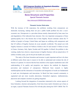
Las Casas.qxd 3/17/08 2:53 PM Page 215 Comparative 3D Finite Element Stress Analysis of Straight and Angled Wedge-Shaped Implant Designs Estevam Barbosa Las Casas, Eng, MSc, PhD1/Paulo César Ferreira, Eng, MSc2/ Carlos Alberto Cimini Jr, Eng, MSc, PhD1/Elson Magalhães Toledo, Eng, MSc, DSc3/ Luis Paulo da Silva Barra, Eng, MSc, DSc2/Mauro Cruz, DDS, MDSci, PhD4 Purpose: The goal of this work was to analyze the stress distribution in 2 wedge-shaped implant designs, straight and angled, by means of a 3-dimensional finite element method (FEM) stress analysis. Materials and Methods: A model was generated from computerized tomography of a human edentulous mandible with the implants placed in the left first molar region. The model included boundary conditions representing the muscles of mastication and the temporomandibular joint. An axial load of 100 N and a horizontal load of 20 N were separately applied at the tops of the implant abutments, and system equilibrium equations were used to find each muscle intensity force based on its position and direction. The mandibular boundary conditions were modeled considering the anatomy of the supporting muscle system. Cortical and medullary bones were assumed to be homogeneous, isotropic, and linearly elastic. Results: The stress analysis provided results in terms of normal maximum tensile (1) and compressive (3) stress fields. The stress distribution was quite similar for both designs, indicating a good performance of the angled design. Conclusions: Stresses in the angled implant were in general lower than in the straight implant, and the differences between the 2 designs studied were more relevant for the vertical load. No indication was found that angled implants of the type described generate stress-induced problems compared to straight implants. INT J ORAL MAXILLOFAC IMPLANTS 2008;23: 215–225 Key words: biomechanics, dental implants, dental stress analysis, finite element analysis ifferent implant designs have been proposed and tested in an attempt to provide anatomic, prosthetic, esthetic, and functional solutions for partial or total tooth loss. The predictability of different implant systems is supported by many clinical studies. 1,2 Recent systematic reviews 3,4 have demonstrated a survival rate of approximately 96%, with no clinical differences among implant systems.5 Because of the variability of anatomic structures, implants D 1Professor, School of Engineering, Federal University of Minas Gerais, Belo Horizonte, MG, Brazil. 2Professor, Federal University of Juiz de Fora, School of Engineering, Juiz de Fora, MG, Brazil. 3Researcher, Computational Mechanics Coordination, LNCC, Petrópolis, RJ, Brazil. 4Director, Clinest - Clinical Center of Research in Stomatology; Researcher and Professor, São Leopoldo Mandic Research Center–School of Dentistry, Juiz de Fora, MG, Brazil. Correspondence to: Dr Mauro Cruz, São Leopoldo Mandic Research Center, School of Dentistry, Av. Rio Branco, 2288/1205 Juiz de Fora, MG, 36016-310, Brazil. E-mail: [email protected] cannot always be placed in the desired number and location. For this reason, implants are sometimes placed in an inclined position.6–8 A common clinical procedure involves tilting the straight implant in cases where it is important to avoid anatomic structures such as the inferior alveolar nerve at the posterior region of the mandible or the maxillary sinus.6 To obtain the necessary prosthetic parallelism, tilted implants need angled abutments; this addition makes them geometrically similar to angled implants. The biomechanical behavior of these implants compared to vertically positioned implants has been the subject of previous works. 8–11 The results of these works showed no clinical differences between tilted and vertically positioned implants. Angled implants have been proposed12–14 for better adjustment of the implant shape to the residual bone morphology, which could increase the applicability and functionality of the technique. The biomechanical behavior of such implants was analyzed and compared to the straight implant design.15,16 Many studies have focused on the biomechanical behavior and the clinical outcomes of angled implants, with The International Journal of Oral & Maxillofacial Implants COPYRIGHT © 2008 BY QUINTESSENCE PUBLISHING CO, INC. PRINTING OF THIS DOCUMENT IS RESTRICTED TO PERSONAL USE ONLY. NO PART OF THIS ARTICLE MAY BE REPRODUCED OR TRANSMITTED IN ANY FORM WITHOUT WRITTEN PERMISSION FROM THE PUBLISHER 215 Las Casas.qxd 3/17/08 2:53 PM Page 216 Las Casas et al Fig 1a CT scan of the mandible. the angle situated on the body12,13,15,17 or between the implant and the abutments. 7,9,18–24 Based on these studies, such implants have been recommended for anatomic, prosthetic, and biomechanical reasons. Different implant shapes and prosthetic concepts have been studied25–31 in the search for improved shapes to enhance the applicability of the implants. Angled16 and straight32–34 wedge-shaped implants are 2 of these alternatives. The use of finite element method (FEM) in the mechanical analysis of dental implants has been described by many authors.7,15,26,28,35–42 This method presents a suitable degree of reliability and accuracy43–48 without the risk and expense of implantation, as pointed out by Cook et al.49 To study a complex mechanical problem, FEM can be used to simulate the stress distribution, dividing the problem geometry into a collection of much smaller and simpler elements. Complicated geometric structures are thus converted into meshes in a computer set. The resulting models consist of elements, nodes, and predefined boundary conditions. Displacement and stress caused by loading on each node can then be calculated by a computer program.48,50 Image data obtained with the aid of computerized tomography (CT), 3-dimensional scanning (3D), or magnetic resonance imaging is used to generate the FEM model and the mesh necessary for the analysis. The quantitative data obtained by the stress analysis can be correlated51 with the physiologic bone threshold.52–57 The purpose of this work was to analyze and compare stress distribution around 2 implant shapes, straight and angled, under vertical and horizontal loading by means of a 3D FEM stress analysis. 216 Fig 1b Cross section. MATERIALS AND METHODS The geometric model generation was based on previous works with the development of a model of implants fixed to an edentulous mandible.32,34,43,46 Modeling The model of the human mandible was generated based on CT (Pro-Speed, GE, Medical Systems, Fairfield, CT; Fig 1). Sections of the CT scan were digitalized and used as input for the Ansys pre-processor (Ansys, Canonsburg, PA). Coordinates of the points in each of the available sections served as a basis for the generation of lines (Fig 2a), defining the contour surfaces (Fig 2b) and resulting in a solid model of the mandible, include internal boundaries between the cortical and medullary bone. The implants considered had a wedge-shaped basic shape with either a straight long axis or an angled long axis (Bioform implant; Maxtron Co, Juiz de Fora, MG, Brazil). The straight implant had a length of 13 mm and a diameter of 4 mm (Fig 3a). The angled implants are of 2 different types, lateral and frontal angled. The lateral angled implant has a long axis inclined toward the narrowest face of the body (named the “lateral face” of the implant) 4 mm from the platform, with 3 different slopes (25 degrees, 40 degrees, 55 degrees; Fig 3b). The frontal angled implant has a deviation of the long axis toward the largest face of the body (named the “frontal face” of the implant) 4 mm from the platform; it also is available in 3 different slopes (25 degrees, 35 degrees, 45 degrees; Fig 3c). Both are designed to contour anatomic structures such as the sinus, inferior alveolar Volume 23, Number 2, 2008 COPYRIGHT © 2008 BY QUINTESSENCE PUBLISHING CO, INC. PRINTING OF THIS DOCUMENT IS RESTRICTED TO PERSONAL USE ONLY. NO PART OF THIS ARTICLE MAY BE REPRODUCED OR TRANSMITTED IN ANY FORM WITHOUT WRITTEN PERMISSION FROM THE PUBLISHER Las Casas.qxd 3/17/08 2:54 PM Page 217 Las Casas et al Fig 2a Contour lines. Fig 2b The use of contour lines to model surfaces. Fig 3a Straight wedge-shaped implant. Fig 4a Clinical indications for the use of angled implants. Fig 3b Laterally angled wedge-shaped implant. nerve and mental foramina and to enhance prosthetic, esthetic, and biomechanical conditions (Fig 4a). The subject of this study was a front-angled implant with a diameter of 4 mm, a length of 14 mm, and a slope of 35 degrees.The dimensions of the considered implants were chosen to match previously reported FEM studies. All implants had 3 notches on each side of the largest face of the body (Fig 3). Information on the dimensions of the implants was provided by the manufacturer. The situation simulated was the placement of an implant in the first Fig 3c Frontally angled wedge-shaped implant. Fig 4b Detail of the model in the first molar region. molar region (Fig 4b). A layer of cortical bone of 2 mm was modeled around the implant neck, and the body was modeled as being embedded in medullary bone and surrounded by a 1-mm layer of compact bone.35 Thus, the model was a simplification of the more complex configuration observed in actual cases.1 The straight implant was positioned vertically through the mandible, while the angled implant was placed with the straight apical portion of the body tilted toward the buccal surface of the mandible, within the cortical layer (Fig 5). The International Journal of Oral & Maxillofacial Implants COPYRIGHT © 2008 BY QUINTESSENCE PUBLISHING CO, INC. PRINTING OF THIS DOCUMENT IS RESTRICTED TO PERSONAL USE ONLY. NO PART OF THIS ARTICLE MAY BE REPRODUCED OR TRANSMITTED IN ANY FORM WITHOUT WRITTEN PERMISSION FROM THE PUBLISHER 217 Las Casas.qxd 3/17/08 2:54 PM Page 218 Las Casas et al Fig 5 Lingual Buccal Lingual Each implant in the planned position. Buccal Abutment Implant Cortical bone Medullar bone Angled Table 1 Straight Mesh Data No. of elements No. of nodes Region Straight Angled Straight Angled Implant-abutment Molar region Complete model 17,897 34,188 53,057 17,902 34,426 53,790 26,552 47,263 75,941 26,389 47,245 76,358 The geometric model was meshed with tetrahedral isoparametric quadratic elements consisting of 4 triangular faces, 4 vertices, and 10 nodes. The mesh used was defined through refinement tests. The convergence of the results was verified in the cervical region of the implant, which is subjected to the highest stress levels. The mesh used had around 62% of the elements concentrated in the region where the implant was placed (Table 1). Vertical loads (axial) of 100 N and horizontal loads (90 degrees to the vertical) of 20 N were applied at the central node in the upper surface of the abutment15,27,38 (Figs 6a and 6b). The solid model resulting from the Boolean intersection of the implant and mandible represents the assumption of complete osseointegration, restricting any relative displacement between implant and bone. Load and Support System The final model was supported by force vectors simulating the actions of the muscles of mastication (masseter, medial pterygoid, lateral pterygoid, and temporalis) and the temporomandibular joints50 (Fig 7). The acting forces generated by the mastication muscles and transferred to the vectors were calculated based on the transverse sections, as proposed by Inou et al.46 The data obtained from this reference indicate the following relationships between the muscle actions, based on the average size of their cross-sectional areas at the mandibular interface: • M = 1.72 LP • T = 0.99 LP • MP = 1.15 LP where M is the masseter, LP is the lateral pterygoid, T is the temporalis, and MP is the medial pterygoid. For horizontal and vertical loading, both condyles were completely restrained. The values of muscular forces for both loading cases were determined by the moment equilibrium equation around the axis connecting the condyles, which is given by the expression: → → → → → → → →→ → → (rM ⫻ 2M + 2 MP ⫻ rMP + 2LP ⫻ rLP + 2T ⫻ rT + P0 ⫻ rP ) • e = 0 0 218 Volume 23, Number 2, 2008 COPYRIGHT © 2008 BY QUINTESSENCE PUBLISHING CO, INC. PRINTING OF THIS DOCUMENT IS RESTRICTED TO PERSONAL USE ONLY. NO PART OF THIS ARTICLE MAY BE REPRODUCED OR TRANSMITTED IN ANY FORM WITHOUT WRITTEN PERMISSION FROM THE PUBLISHER Las Casas.qxd 3/17/08 2:54 PM Page 219 Las Casas et al Horizontal load Vertical load T cos ␣ = 0 cos  = –1 cos ␥ = 0 P0 1 M LP MP T M MP P0 a Table 2 Fig 7 Directions of the muscular forces and boundary conditions. Distance Vector Components in mm Table 3 Director Cosines of the Resultant Muscular Forces (Right Side) Direction X rM rT r LP r MP rP Y 0.0 0.0 0.0 0.0 0.0 0 28.07 30.61 9.56 27.67 80.63 33.01 5.27 6.31 38.97 23.89 Resultants of the muscular forces Vertical (100 N) Horizontal (20 N) M MP 49.251 1.787 32.626 1.195 Cosine Z Table 4 Resultants of the Muscular Forces for Vertical and Horizontal Loads Load P0 3 Load application. Vector distance 2 cos ␣ = –0.907 cos  = 0.420 cos ␥ = 0 b Figs 6a and 6b LP LP T 28.634 28.348 1.039 1.029 Variables rM, rMP, rLP, and rT and rP0 are the distance vectors from the load application points of the muscles forces M, MP, LP, and T and of the axial implant loads P0 to the (1-2) axis passing through the tops of the condyles, respectively. The same equation was used for axial and horizontal loads, with the distance varying accordingly. The symbol ⫻ denotes the vector product, the symbol ([bullet]) denotes the inner vector product, and → e is the unit vector in the condylar axis direction. The positions of the muscular forces and axial load are given in vector form in Table 2. Under the assumption of symmetric muscular loads, asymmetry is generated by the reaction forces in the condyles. Moment equilibrium in the axis, obtained by the finite element analysis, results in different condyle forces and thus an asymmetric stress distribution in the model. ␣ Muscle Masseter Medial pterygoid Lateral pterygoid Temporalis P0 horizontal P0 vertical Table 5 Material  –0.043 0.587 0.714 –0.325 –0.907 0 –0.011 –0.165 –0.692 0.219 0.420 –1 ␥ 0.999 0.792 0.106 0.920 0 0 Elastic Materials Properties Elasticity modulus Cortical bone 13,700 MPa Medullary bone 1,370 MPa Titanium 110,000 MPa Poisson's ratio 0.30 0.30 0.33 References 15, 27, 29, 35, 37, 38, 49 27, 35, 37, 38 29, 39 The locations and directions of the muscle force vectors were obtained from the literature.46,47 Their resultants were considered to be acting on the centroid of the elements included in the areas of muscular action. Force directions are described in terms of director cosines, as given in Table 3. Obtained values for each muscular force, considering both vertical and horizontal loads, are listed in Table 4. Elastic properties for cortical bone, medullary bone, and titanium were extracted from the current literature and are listed in Table 5. Thicknesses of the cortical and medullary bone were based on the CT sections of the mandible. The bone was assumed to be isotropic, homogeneous, and linearly elastic, which allowed immediate extrapolation of the obtained results for different load levels. The International Journal of Oral & Maxillofacial Implants COPYRIGHT © 2008 BY QUINTESSENCE PUBLISHING CO, INC. PRINTING OF THIS DOCUMENT IS RESTRICTED TO PERSONAL USE ONLY. NO PART OF THIS ARTICLE MAY BE REPRODUCED OR TRANSMITTED IN ANY FORM WITHOUT WRITTEN PERMISSION FROM THE PUBLISHER 219 Las Casas.qxd 3/17/08 2:54 PM Page 220 Las Casas et al Cervical Buccolingual Mesiodistal Cervical Fig 8 Straight implant contour lines illustrating the stress path. The analyses were done using the commercial finite element code Ansys and processed in a Pentium 4 personal computer. RESULTS Principal stresses were obtained from the analysis, allowing the consideration of maximum compressive and tensile stresses, as bone behavior under tension and compression is essentially different. Figures 8 and 9 show points distributed along the implantbone interface at a cervical, a buccolingual, and a mesiodistal section used to plot maximum (1) and minimum (3) principal stresses. Along the paths shown in Figs 10 and 11, graphs were generated to make comparisons between the maximum (1) and minimum (3) principal stresses for both implant designs under vertical and horizontal loads (Figs 10 to 13). Under vertical load, the straight implant presented a high compressive peak stress concentration on 1 side of the neck and a smooth distribution along the body (Figs 10 and 11), which was in agreement with previously reported results.32,34 For the angled implant under vertical load (Figs 10 and 11), the stress distribution was quite similar. The largest tensile stresses occurred at the larger curvature region (buccolingual line) near the cervical area, while the highest compressive stresses occurred on the cervical line at the lingual side. A similar pattern was observed for horizontal loading (Fig 13) in case of compressive stresses, although different values were found. On the mesiodistal cross section, no considerable differences were observed for either design, but the maximum compressive stress distribution showed a slight increase in the region around point A of the angled implant compared to the straight implant. Differences were noted for horizontal and vertical loading. Tables 6 and 7 present the principal stresses 220 Fig 9 Buccolingual Mesiodistal Angled implant contour lines illustrating the stress path. in the sections indicated in Figs 8 and 9, summarizing the obtained results for vertical and horizontal loading. More pronounced difference was observed for vertical loading at cervical point B. The difference reached a factor of 2.25 for compressive stresses and, for horizontal loading, a factor of 1.95, with higher values for the straight implant in both cases. In general, stresses in the angled implant were lower than for the straight model, with the exception of point A under vertical loading. DISCUSSION The purpose of this investigation was to provide an analysis between 2 different geometric configurations of implants and to compare their biomechanical behavior. Even with the simplifications made (homogeneity of the bone quality, symmetric muscle action, complete osseointegration, and static load) the model results may be very close to actual situations observed in clinical studies.39,43–45,47 Many of the assumptions adopted in the current model should be taken into account in the analysis of the results. Complete osseointegration is not observed in clinical studies, as the level of osseointegration is highly variable. In a 3D finite element analysis of osseointegration percentages and patterns on implant-bone interfacial stresses, Papavasiliou et al40 concluded that different degrees of osseointegration do not affect the stress levels or distributions for axial or oblique loads. So, fixing a value of 100% in a comparative study does not affect the conclusions. Mesh density is another relevant parameter. As the surfaces are curved, improving the mesh usually improves the results for the discrete model (increasing the accuracy in regions of high stress gradients). Another effect of increasing the number of elements is to reduce sharp angles created artificially by the process of substituting the model with the mesh, Volume 23, Number 2, 2008 COPYRIGHT © 2008 BY QUINTESSENCE PUBLISHING CO, INC. PRINTING OF THIS DOCUMENT IS RESTRICTED TO PERSONAL USE ONLY. NO PART OF THIS ARTICLE MAY BE REPRODUCED OR TRANSMITTED IN ANY FORM WITHOUT WRITTEN PERMISSION FROM THE PUBLISHER Las Casas.qxd 3/17/08 2:54 PM Page 221 Las Casas et al Straight implant 3.0 2.0 2.0 1.0 1.0 0.0 0.0 –1.0 MPa MPa Angled implant 3.0 –2.0 –1.0 –2.0 –3.0 –3.0 –4.0 –4.0 Cervical Buccolingual Mesiodistal –5.0 –6.0 0 5 10 15 20 25 Cervical Buccolingual Mesiodistal –5.0 –6.0 30 35 0 5 10 mm Straight implant Cervical Buccolingual Mesiodistal 5 Figs 11a and 11b 10 15 20 25 30 35 30 35 Cervical Buccolingual Mesiodistal 0 5 10 15 20 25 mm Straight implant 5.0 5.0 3.0 MPa 4.0 3.0 2.0 1.0 1.0 0.0 0.0 –1.0 –1.0 –2.0 –2.0 5 10 15 20 25 30 35 Cervical Buccolingual Mesiodistal 6.0 4.0 2.0 Angled implant 7.0 Cervical Buccolingual Mesiodistal 6.0 MPa 35 Minor principal stresses along previously defined paths—vertical load (3). 7.0 0 5 mm Figs 12a and 12b 30 Angled implant 0 –1.0 –2.0 –3.0 –4.0 –5.0 –6.0 –7.0 –8.0 –9.0 –10.0 –11.0 –12.0 –13.0 mm 0 25 Major principal stresses along previously defined paths—vertical load (1). 0 –1.0 –2.0 –3.0 –4.0 –5.0 –6.0 –7.0 –8.0 –9.0 –10.0 –11.0 –12.0 –13.0 0 20 mm MPa MPa Figs 10a and 10b 15 10 15 20 25 30 35 mm Major principal stresses along previously defined paths—horizontal load (1). The International Journal of Oral & Maxillofacial Implants COPYRIGHT © 2008 BY QUINTESSENCE PUBLISHING CO, INC. PRINTING OF THIS DOCUMENT IS RESTRICTED TO PERSONAL USE ONLY. NO PART OF THIS ARTICLE MAY BE REPRODUCED OR TRANSMITTED IN ANY FORM WITHOUT WRITTEN PERMISSION FROM THE PUBLISHER 221 Las Casas.qxd 3/17/08 2:54 PM Page 222 Las Casas et al Straight implant Angled implant 1.0 0.0 0.0 –1.0 –1.0 –2.0 –2.0 Stress (MPa) Stress (MPa) 1.0 –3.0 –4.0 –5.0 –6.0 –3.0 –4.0 –5.0 –6.0 Cervical Buccolingual Mesiodistal –7.0 –8.0 –7.0 Cervical Buccolingual Mesiodistal –8.0 –9.0 –9.0 0 5 10 15 20 25 30 35 0 5 10 Millimeters Figs 13a and 13b Table 6 25 30 35 Millimeters Stresses Under Vertical Loading (100 N) Straight implant –0.34 –0.88 –2.00 –3.89 –0.29 3 (MPa) –5.90 –7.12 –9.74 –10.44 –1.40 Table 7 Angled implant 0.21 –1.21 –2.52 –4.11 –0.56 –2.62 –8.13 –10.78 –10.41 –2.20 Stresses Under Horizontal Loading (20 N) Straight implant 1 (MPa) 3 (MPa) reducing artificial peak stresses by improving the representation of the actual geometry. The consideration of a limit for the interface resistance between bone and implant, which was not included in the present model, is an interesting topic for future models. It requires nonlinear treatment of the problem of contact and fracture at the implantbone boundary. In recent years, studies have shown that a more precise consideration of the physical processes in finite element models used in dental biomechanics can lead to more reliable results.27,43,46,48 The modeling of the whole mandible, with the muscles, temporomandibular joints, and the supporting system can bring the model closer to reality. 43,46 Three-dimensional modeling, special attention to boundary conditions, the use of a fine mesh with an appropriate number of degrees of freedom— all these factors contribute to the precision of the computational results.43,46,48,49 The modeled muscular force action at the bone surface generated stresses as high as those obtained around the implant, as shown in previous studies.32,34 This fact provides a qualitative way of comparing the obtained stress levels and suggests that modeling of the whole mandible is important.43–46 222 20 Minor principal stresses along previously defined paths—horizontal load (3). 1 (MPa) Cervical Buccal Lingual Mesial Distal Apical 15 Cervical Buccal Lingual Mesial Distal Apical 1 (MPa) 3 (MPa) 6.44 –1.06 1.97 2.55 0.00 0.54 –7.67 -1.18 –2.68 –0.11 Angled implant 1 (MPa) 3 (MPa) 3.30 –1.12 1.63 2.48 0.39 –0.11 –8.37 –1.44 2.51 0.00 Comparative FEM stress analyses between different implant designs or different implant prosthetic concepts under the same conditions have been previously reported.26,27,30,36,38,42 They have often been used to compare new designs to classical implant forms. Comparisons under different modeling conditions can serve as a reference but do not provide conclusive proof. However, different studies have presented comparisons with the Brånemark system. This system can be used as a reference, as it has been thoroughly studied and has provided good clinical results.26,29,36 In previous works, Cruz 32 and Cruz and et al 34 studied the biomechanical behavior of the wedgeshaped straight implants. These works showed how the straight wedge-shaped implant relates to the Brånemark system in terms of biomechanical behavior. Therefore, the straight wedge-shaped implant can serve as a reference for comparison with the angled wedge-shaped implant, and the results presented here can then indirectly establish the relationship between the behavior of the wedge-shaped angled design and the usual standard. The effect of having an angled design rather than a straight shape can also be studied in terms of stresses. Volume 23, Number 2, 2008 COPYRIGHT © 2008 BY QUINTESSENCE PUBLISHING CO, INC. PRINTING OF THIS DOCUMENT IS RESTRICTED TO PERSONAL USE ONLY. NO PART OF THIS ARTICLE MAY BE REPRODUCED OR TRANSMITTED IN ANY FORM WITHOUT WRITTEN PERMISSION FROM THE PUBLISHER Las Casas.qxd 3/17/08 2:54 PM Page 223 Las Casas et al In the present study, stresses were generally lower in the angled implant than in the straight implant, indicating that stress-induced bone resorption should not be more critical in this design than in more usual straight implants. This finding was unexpected, as the indication for such implant designs comes not from the need to reduce stresses but from occasional anatomic difficulties in the use of more traditional solutions.12,13 The larger differences in peak stresses were for vertical loading for compressive stresses on the lingual side of the cervical region of the straight design. As in the case of horizontal load, this increase was also larger for the straight implant. Interpretation of the numerical results should take into account that in normal function, during mastication, the vertical components of the loading are higher than the horizontal components, while in parafunction, horizontal loads can be dominant. Canay et al15 reported a 2-dimensional analysis of vertical and angled implants of the ITI Bonefit system. Unlike the design modeled in the present study, the inclined part of the implants in the Canay et al study was outside the bone. The designs were recommended for 2 quite different problems and submitted to different stresses. The obtained results were not conclusive in terms of the clinical performance of the angled implant, even though they indicated that angled implants seem to provide an effective solution that does not compromise the stress levels developed in the bone. The same observation was made by Clelland et al9 with respect to angled abutments, by Schroeder et al12 and Sutter et al13 with respect to angled implants, and by Satoh et al7 with respect to both. Conversely, the angled implant can provide better structure for the prostheses17,23 by keeping the angle of the implant inside the bone and loading to a smoother stress distribution. It also often allows bicortical implant fixation when the implant is placed in the mandible with the apex of the implant resting in the buccal cortex. Data based on patient observation would be required to assess the comparative advantages of this design in specific clinical situations. Rieger et al26 and Inou et al,46 based on previously published physiologic thresholds, reported that in their experiments bone resorption occurred in regions where the stress concentration was under or over the physiologic limits. In regions where the stress was within those limits, the bone maintained its morphology. The results of the present investigation indicated that both designs analyzed showed stresses in the same stress range (ie, within the physiologic levels).55,56 A shape that takes peak stresses away from the bone crest should be chosen for clinical use, as stated by Akpinar et al.37 This did not totally occur with the present designs, but the stress distribution pattern of this analysis showed values in the neck of the same magnitude as those at the muscle insertion, as previously described by Cruz32 and Cruz et al34,57 for the straight design, which means that, for the considered load, the stresses were at the same level as those generated by the muscle actions. The 2 designs studied demonstrated a gradual distribution of the load from the coronal to the apical region, with a concentration of stress at the neck. CONCLUSIONS Stress analysis of 2 different wedge-shaped designs, straight and angled, using the finite element method led to the following conclusions: • Stresses were generally lower in the angled implant than in the straight implant. • The differences between the designs studied were more relevant for the vertical load. • Under the considered loads, both implants presented low stress on the medullary bone area, indicating that the major concentration was actually in the cortical layer, which agrees with previous results. • A low stress concentration was observed in the apical area for both designs. • No indication was found that angled implants of the type described generate stress-induced problems compared to straight implants. ACKNOWLEDGMENTS The authors wish to thank the late Dr Clóvis da Cruz Reis, who sowed the seed of this idea. This research was funded by grants from FAPEMIG-FIEMG (Research Support Foundation of the State of Minas Gerais), IEL (Euvaldo Lodi Institute), and Maxtron, Juiz de Fora, MG, Brazil. It was supported by the School of Engineering, Federal University of Minas Gerais (UFMG); School of Engineering, Federal University of Juiz de Fora (UFJF); the Research Center for Computational Methods in Engineering (NUMEC); the Clinical Center of Research in Stomatology (CLINEST); and the National Laboratory for Scientific Computing (LNCC). Dr Cruz is a scientific consultant for the Maxtron Company. The International Journal of Oral & Maxillofacial Implants COPYRIGHT © 2008 BY QUINTESSENCE PUBLISHING CO, INC. PRINTING OF THIS DOCUMENT IS RESTRICTED TO PERSONAL USE ONLY. NO PART OF THIS ARTICLE MAY BE REPRODUCED OR TRANSMITTED IN ANY FORM WITHOUT WRITTEN PERMISSION FROM THE PUBLISHER 223 Las Casas.qxd 3/17/08 2:54 PM Page 224 Las Casas et al REFERENCES 1. Adell R, Lekholm U, Rockler B, Brånemark P-I. A 15-year study of osseointegrated implants in the treatment of the edentulous jaw. Int J Oral Surg 1981;10:387–416. 2. Buser D, Mericske-Stern R, Bernard JP, et al. Long-term evaluation of non-submerged ITI implants. Part 1: 8-year life table analysis of a prospective multi-center study with 2359 implants. Clin Oral Implants Res 1997;8:161–172. 3. Eckert SE, Choi Y-G, Sánchez AR, Koka S. Comparison of dental implant systems: Quality of clinical evidence and prediction of 5-year survival. Int J Oral Maxillofac Implants 2005;20:406–415. 4. Pjetursson BE, Tan K, Lang NP, Bragger U, Egger M, Zwahlen M. A systematic review of the survival and complication rates of fixed partial dentures (FPDs) after an observation period of at least 5 years. Clin Oral Implants Res 2004;15:625–642. 5. Esposito M, Grusovin MG, Coulthard P, Thomsen P, Worthington HV. A 5-year follow-up comparative analysis of the efficacy of various osseointegrated dental implant systems: A systematic review of randomized controlled clinical trials. Int J Oral Maxillofac Implants 2005;20:557–568. 6. Krekmanov L, Kahn M, Rangert B, Lindström H. Tilting of posterior mandibular and maxillary implants for improved prosthesis support. Int J Oral Maxillofac Implants 2000;15:405–414. 7. Satoh T, Maeda Y, Komiyama Y. Biomechanical rationale for intentionally inclined implants in the posterior mandible using 3D finite element analysis. Int J Oral Maxillofac Implants 2005;20:533–539. 8. Çaglar A, Aydin C, Ozen J, Yilmaz C, Korkmaz T. Effects of mesiodistal inclination of implants on stress distribution in implant-supported fixed prostheses. Int J Oral Maxillofac Implants 2006;21:36–44. 9. Clelland NL, Gilat A, McGlumphy EA, Brantley WA. A photoelastic and strain gauge analysis of angled abutments for an implant system. Int J Oral Maxillofac Implants 1993;8:541–548. 10. Celletti R, Pameijer CH, Bracchetti G, Donath K, Persichetti G, Visani I. Histologic evaluation of osseointegrated implants restored in nonaxial functional occlusion with preangled abutments. Int J Periodontics Restorative Dent 1995;15:562–573. 11. Eger DE, Gunsolley JC, Feldman S. Comparison of angled and standard abutments and their effect on clinical outcomes: A preliminary report. Int J Oral Maxillofac Implants 2000;15:819–823. 12. Schroeder A, Sutter F, Krekeler G. Orale Implantologie: Allgemeine Grundlagen Und ITI-Hohlzylindersystem. Stuttgart, Germany: Georg Thieme Verlag, 1988:377. 13. Sutter F, Schroeder A, Buser DA. The new concept of ITI hollow cylinder and hollow screw implants, 1: Engineering and design. Int J Oral Maxillofac Implants 1988;3:161–172. 14. ten Bruggenkate CM, Sutter F, Oosterbeek HS, Schroeder A. Indications for angled implants. J Prosthet Dent 1992;67:85–93. 15. Canay S, Hersek N, Akpinar I, Asik Z. Comparison of stress distribution around vertical and angled implants with finite-element analysis. Quintessence Int 1996;27:591–598. 16. Ferreira PC. Modeling of the Biomechanical Behavior of an Edentulous Mandible with Vertical and Angled Implants [thesis]. Belo Horizonte, Brazil: School of Engineering, Federal University of Minas Gerais, 2003. 17. ten Bruggenkate CM, Oosterbeek HS, Krekeler G, Asikainen PJ. The placement of angled implants in the edentulous maxillae for the use of overdentures. J Prosthet Dent 1991;66:807–809. 224 18. Kallus T, Henry P, Jemt T. Clinical evaluation of angulated abutments for the Brånemark system: A pilot study. Int J Oral Maxillofac Implants 1990;5:39–45. 19. Clelland NL, Gilat A. The effect of abutment angulation on stress transfer for an implant. J Prosthodont 1992;1:24–28. 20. Gelb DA, Lazzara RJ. Hierarchy of objectives in implant placement to maximize esthetics: Use of pre-angulated abutments. Int J Periodontics Restorative Dent 1993;13:277–287. 21. Clelland NL, Lee JK, Bimbenet OC, Brantley WA. A three-dimensional finite element stress analysis of angled abutments for an implant placed in the anterior maxilla. J Prosthodont 1995;4:95–100. 22. Balshi TJ, Ekfeldt A, Stenberg T, Vrielinck L. Three-year evaluation of Brånemark implants connected to angulated abutments. Int J Oral Maxillofac Implants 1997;12:52–58. 23. Tuncelli B, Poyrazoglu E, Koyluoglu AM, Tezcan S. Comparison of load transfer by angulated, standard and inclined implant abutments. Eur J Prosthodont Restor Dent 1997;5:85–88. 24. Dario LJ. A maxillary implant overdenture that utilizes anglecorrecting abutments. J Prosthodont 2002;11:41–45. 25. Rieger MR, Fareed K, Adams WK, Tanquist R. A Bone stress distribution for three endosseous implants. J Prosthet Dent 1989;61:223–228. 26. Rieger MR, Adams WK, Kinzel GL. A finite element survey of eleven endosseous implants. J Prosthet Dent 1990;63:457–465. 27. Meijer HJA, Kuiper JH, Starmans FJM, Bosman F. Stress distribution around dental implants: Influence of superstructure, length of implants, and height of mandible. J Prosthet Dent 1992;68:96–102. 28. Tada S, Stegaroiu R, Kitamura E, Miyakawa O, Kusakari H. Influence of implant design and bone quality on stress/strain distribution in bone around implants: A 3-dimensional finite element analysis. Int J Oral Maxillofac Implants 2003;18:357–368. 29. Bozkaya D, Muftu S, Muftu A. Evaluation of load transfer characteristics of five different implants in compact bone at different load levels by finite elements analysis. J Prosthet Dent 2004;92:523–530. 30. Geramy A, Morgano SM. Finite element analysis of three designs of an implant-supported molar crown. J Prosthet Dent 2004;92:434–440. 31. Koca OL, Eskitascioglu G, Usumez A. Three-dimensional finiteelement analysis of functional stresses in different bone locations produced by implants placed in the maxillary posterior region of the sinus floor. J Prosthet Dent 2005;93:38–44. 32. Cruz M. Tri-dimensional Stress Analysis Around a Cuneiform Implant by the Finite Element Method [thesis]. Campinas, Brazil: Camil Castelo Branco University, 2001. 33. Cruz M, Reis CC, Mattos FF. Implant-induced expansion of atrophic ridges for the placement of implants. J Prosthet Dent 2001;85:377–381. 34. Cruz M, Wassal T, Toledo EM, Barra LPS, Lemonge ACC. Threedimensional finite element stress analysis of a cuneiformgeometry implant. Int J Oral Maxillofac Implants 2003;18:675–684. 35. Borchers L, Reichart P. Three-dimensional stress distribution around a dental implant at different stages of interface development. J Dent Res 1983;62:155–159. 36. Siegele D, Soltész U. Numerical investigations of the influence of implant shape on stress distribution in the jaw bone. Int J Oral Maxillofac Implants 1989;4:333–340. 37. Akpinar I, Demirel F, Parnas L, Sahin S. A comparison of stress and strain distribution characteristics of two different rigid implant designs for distal-extension fixed prostheses. Quintessence Int 1996;27:11–17. Volume 23, Number 2, 2008 COPYRIGHT © 2008 BY QUINTESSENCE PUBLISHING CO, INC. PRINTING OF THIS DOCUMENT IS RESTRICTED TO PERSONAL USE ONLY. NO PART OF THIS ARTICLE MAY BE REPRODUCED OR TRANSMITTED IN ANY FORM WITHOUT WRITTEN PERMISSION FROM THE PUBLISHER Las Casas.qxd 3/17/08 2:54 PM Page 225 Las Casas et al 38. Meijer HJA, Starmans FJM, Steen WHA, Bosman F. Loading conditions of endosseous implants in an edentulous human mandible: A three-dimensional, finite-element study. J Oral Rehabil 1996;23:757–763. 39. Baiamonte T, Abbate MF, Pizzarello F, Lozada JL, James R. The experimental verification of the efficacy of finite element modeling to dental implant systems. J Oral Implantol 1996;22:104–110. 40. Papavasiliou G, Kamposiora P, Bayne SC, Felton DA. 3D-FEA of osseointegration percentages and patterns on implant-bone interfacial stresses. J Dent 1997;25:485–491. 41. Sevimay M, Turhan F, Kiliçarslan MA, Eskitacioglu G. Threedimensional finite element analysis of the effect of different bone quality on stress distribution in an implant-supported crown. J Prosthet Dent 2005;93:227–234. 42. Yokoyama S, Wakabayashi N, Shiota M, Ohyama T. Stress analysis in edentulous mandibular bone supporting implantretained 1-piece or multiple superstructures. Int J Oral Maxillofac Implants 2005;20:578–583. 43. Koolstra JH, Van Eijden TMGJ. Application and validation of a three-dimensional mathematical model of the human masticatory system in vivo. J Biomechanics 1992;25:175–187. 44. Korioth TWP, Romilly DP, Hannam AG. Three-dimensional finite element stress analysis of the dentate human mandible. Am J Phys Anthropol 1992;88:69–96. 45. Keyak JH, Fourkas MG, Meagher JM, Skinner HB. Validation of the automated method of three-dimensional finite element modeling of bone. J Biomed Eng 1993;15:505–509. 46. Inou N, Iioka Y, Fujiwara H, Maki K. Functional adaptation of mandibular bone. In: Hayashi K, Ishikawa H. Computational Biomechanics. Heidelberg, Germany: Springer-Verlag, 1996: 23–42. 47. Koolstra JH, Van Eijden TMGJ. The jaw open-close movements predicted by biomechanical modeling. J Biomechanics 1997;30:943–950. 48. Geng J-P, Tan KBC, Liu G-R. Application of finite element analysis in implant dentistry: A review of the literature. J Prosthet Dent 2001;85:585–598. 49. Cook SD, Weinstein AM, Klawitter JJ. A three-dimensional finite element analysis of a porous rooted Co-Cr-Mo alloy dental implant. J Dent Res 1982;61:25–29. 50. De Vocht JW, Goel VK, Zeitler DL, Lew D, Hoffman EA. Development of a finite element model to simulate and study the biomechanics of the temporomandibular joint. 1999:1-9. Available at: https://medlineplus.nlm.nih.gov/research/visible/ vhp_conf/devocht/vhppaper.htm 51. Saab XE, Griggs JA, Powers JM, Engelmeier RL. Effect of abutment angulation on the strain on the bone around an implant in the anterior maxilla: A finite element study. J Prosthet Dent 2007;97:85–92. 52. Frost HM. Bone “mass” and the “mechanostat”: A proposal. Anat Rec 1987;219:1–9. 53. Frost HM. Skeletal structural adaptations to mechanical usage (SATMU): 1. Redefining Wolff’s Law: The bone modeling problem. Anat Rec 1990;226:403–413. 54. Frost HM. Skeletal structural adaptations to mechanical usage (SATMU): 2. Redefining Wolff’s Law: The remodeling problem. Anat Rec 1990;226:414–422. 55. Papavasiliou G, Kamposiora P, Bayne SC, Felton DA. Threedimensional finite element analysis of stress-distribution around single tooth implants as a function of bony support, prosthesis type, and loading during function. J Prosthet Dent 1996;76:633–640. 56. Garant PR. Bone. From: Oral Cells and Tissues. Chicago: Quintessence, 2003:195–238. 57. Cruz M, Lourenço AF, Toledo EM, Barra LPS, Lemonge ACC, Wassall T. Finite element stress analysis of cuneiform and cylindrical threaded implant geometries. Technol Health Care 2006;14:421–438. The International Journal of Oral & Maxillofacial Implants COPYRIGHT © 2008 BY QUINTESSENCE PUBLISHING CO, INC. PRINTING OF THIS DOCUMENT IS RESTRICTED TO PERSONAL USE ONLY. NO PART OF THIS ARTICLE MAY BE REPRODUCED OR TRANSMITTED IN ANY FORM WITHOUT WRITTEN PERMISSION FROM THE PUBLISHER 225
Download