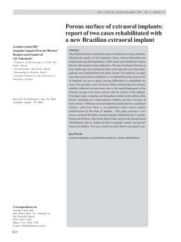
Original Article
Geremia et al.
Effect of cantilever length and inclined implants
on axial force and bending moment in
implant-supported fixed prostheses
Efeito do cantilever e de implantes inclinados na força axial e
momento fletor em próteses fixas implantossuportadas
Abstract
Purpose: To assess the magnitude and distribution of axial forces and bending moments in
abutments as a function of cantilever length and inclination of implants.
Methods: Ten metallic bars simulated frameworks of fixed implant-supported prosthesis over
two master models with five implants: one with all implants straight and parallel (n=5) and one
with the two distal implants tilted (n=5). Strain gauges were fixed on abutments to measure
deformation when a 50N-load was applied on the cantilever at 10, 15, and 20 mm-distance
from the distal abutment. Deformation values were transformed into axial force and bending
moment and analyzed by ANOVA and Tukey test (α = 5%).
Results: Comparing 10 mm- to 20 mm-cantilever, there was an increase of approximately 50%
for axial force and of 70% for saggital bending moment. On the abutment adjacent to the
cantilever, the axial force in the inclined model was 70% lower than in the straight model, and
bending moments did not vary.
Tomás Geremia a
Marcos Michelon Naconecy b
Luis André Mezzomo c
André Cervieri d
Rosemary Sadami Arai Shinkai
c
Department of Prosthodontics, Pontifical Catholic
University of Rio Grande do Sul, Porto Alegre, RS,
Brazil
bPrivate practice, Porto Alegre, RS, Brazil
cGraduate Program in Dentistry, Pontifical Catholic
University of Rio Grande do Sul, Porto Alegre, RS,
Brazil
d INMETRO, Porto Alegre, RS, Brazil
a
Conclusion: The results suggest that the inclination of distal implants does not have any
deleterious biomechanical effect on abutments of the tested models and may reduce the
cantilever effect on force magnitude.
Key words: Biomechanics; cantilever; implant-supported prostheses; strain gauges; tilted
implants
Resumo
Objetivo: Avaliar a magnitude e a distribuição de forças axiais e momentos fletores em pilares
em função da extensão do cantilever e da inclinação dos implantes.
Metodologia: Dez barras metálicas simularam infraestruturas de prótese fixa implantossuportada
sobre dois modelos mestre com 5 implantes: um modelo com todos os implantes retos e
paralelos (n=5) e um com os dois implantes distais inclinados (n=5). Extensômetros foram
fixados nos pilares para medir sua deformação quando uma carga de 50N foi aplicada no
cantilever a 10, 15 e 20 mm do implante distal. Os valores de deformação foram convertidos
em força axial e momento fletor e analisados por ANOVA e teste de Tukey (α = 5%).
Resultados: Comparando-se as distâncias de 10 e 20 mm, houve um aumento de
aproximadamente 50% da força axial e de 70% do momento fletor sagital. No pilar adjacente
ao cantilever, a força axial no modelo com implantes inclinados foi 70% menor que no modelo
com implantes retos, e os momentos fletores não variaram.
Conclusão: Os resultados sugerem que a inclinação dos implantes distais não promoveu
nenhum efeito deletério sobre os pilares nos modelos testados e pode reduzir o efeito do
cantilever na magnitude da força.
Palavras-chave: Biomecânica; extremidade livre; prótese implantossuportada; extensometria;
implantes inclinados
Correspondence:
Tomás Geremia
Pontifícia Universidade Católica do Rio Grande do Sul
Avenida Ipiranga, 6681 – Prédio 6
Porto Alegre, RS – Brazil
90619-900
E-mail: [email protected]
Received: January 12, 2009
Accepted: March 2, 2009
Rev. odonto ciênc. 2009;24(2):145-150
145
Cantilever length and inclined implants
Introduction
Methods
Surgical techniques with inclination of distal implants
have been increasingly used in atrophic maxilla (1-3)
with short- and medium-term clinical success (4-6).
The biomechanical rationale for using inclination of distal
implants is based on the reduction of cantilever length
and increase of the polygonal area for prosthesis
support (4,7). Clinically the inclination of posterior
implants is usually performed with distalization of the
implant emergency sites. In the maxilla, the presence
of large sinuses may require the installation of implants
parallel to the anterior sinus walls with distal inclination
(1,4,6): The ‘apex’ of this implant and the rotation fulcrum
are located in the canine region, and the implant platform
emerges in the first or second premolar region. In the
mandible, the further the mental foramens are from the
alveolar crest, the greater the distal implant inclination
can be, and, consequently, the implant platform is located
more distally. In both situations there are two variables:
inclination of implant body and reduction of cantilever
length due to implant distalization. Furthermore, there is
an inherent increase of length of the prosthesis segment
between the tilted distal implant and its immediate anterior
implant. These characteristics change the prosthesis design
and potentially complicate the predictability of cantilever
models.
Little experimental or long-term clinical evidence is
available regarding the effect of tilting distal implants on
stresses generated in prosthetic components and implant/
bone interface. Finite element analyses have shown
contradictory results on stresses developed at cervical bone
and implant neck with tilted distal implants and different
cantilever configurations (8,9). One recent experimental
study using strain gauges found that the inclination of
distal implants provides better distribution of axial
forces and bending moments in fixed prostheses supported
by four or five abutments in comparison with three
abutments (10). In that study the emergency sites of the
distal implants were kept constant, and a static load was
applied at a fixed cantilever distance to evaluate the
isolated effect of implant inclination on the magnitude
and distribution of force and bending moment. Therefore,
that study showed that for the same cantilever extension
tilted distal implants provided better general biomechanical
behavior than straight implants in fixed prosthesis.
Nevertheless, even with distal implant inclination fixed
prosthesis design may require cantilever to some extent.
Yet no previous experimental study quantified the combined
effect of posterior cantilever length and inclined distal
implants on bone, implants, or prosthetic components
stresses.
Therefore, the present study aimed to evaluate the magnitude
and distribution of axial forces and bending moments in
abutments of fixed implant-supported prostheses for an
edentulous mandibular arch as a function of cantilever length
and inclination of distal implants.
Fabrication of the master models and
metallic frameworks
146
Rev. odonto ciênc. 2009;24(2):145-150
Two master models were fabricated in epoxy resin: one
model with straight implants and another with the distal
implants inclined. The arch (curve of 134.30º and radium
of 17.61 mm) of a human mandible for training in dental
implants (ETH 0301-10 Nobel Biocare, Gothenburg,
Sweden) was transposed to the master models for the
perforation of the implant sites. In the model with straight
implants, five perforations were made with 4 mm-diameter
and 17mm-length, parallel and 1cm apart from each other. In
the model with tilted implants, the three central perforations
were made straight, and the two posterior perforations were
inclined using an index with a 27-degree inclination plane.
Ten 4.0×15-mm screw-type implants (OSS 415, 3i Implant
Innovations, Palm Beach Gardens, FL, USA) were fixed
into the perforations with fluid epoxy resin. The two models
were placed in a pressure chamber at 4 bars for 40 min. After
12 hours, ten 7-mm standard abutments (AB700, 3i Implant
Innovations, Palm Beach Gardens, FL, USA) were attached
with 20 Ncm torque.
The frameworks were waxed up with rectangular section,
3-mm width, 4-mm height, and 20-mm cantilever at the
left side. Around the entrance of the prosthetic screws the
bars had thickness of 2 mm corresponding to the original
thickness of a gold coping (CGC30, 3i Implant Innovations,
Palm Beach Gardens, FL, USA) with addition of 1mm of
wax. Over each master model, five bars were waxed up 1 mm
above the epoxy base. The cantilever was placed on the
left side beginning at the emergency point of the posterior
implant. The wax patterns were sectioned into five segments
and cast with a Pd-Ag alloy (Porson 4, Degussa, Dusseldorf,
Germany) following standard procedures. After finishing,
the segments of each bar were laser-welded (EV LASER
900, Bergamo, Italy) using a stone index previously prepared
to guarantee the accurate transfer of the abutment positions.
To check the passivity of fit of the welded framework,
one screw (WSK15, 3i Implant Innovations, Palm Beach
Gardens, FL, USA) was tightened manually with the bar
positioned on the respective index, and no gap should be
visually detected in any of the other four abutments. This
procedure was performed for all five screws of each bar,
one by one.
The loading point on the cantilever was standardized
at 10, 15, and 20 mm from the posterior emergency of
the distal implant. With a milling machine, a concave
notch was made with half-depth of a round tungsten bur
of 2-mm diameter to mark the three loading sites per bar.
This notch matched the load applicator tip (2-mm diameter)
of a customized mechanical device used to deliver the
50 N static load during the tests. An schematical illustration
of the framework attached to the master model with
straight implants and with tilted distal implants is shown
in Figure 1.
Geremia et al.
Fig. 1. Scheme of the lateral view of the assembly with straight (A) and tilted distal (B) implants. For both models, the
saggital distance between the most anterior and posterior points of the implant platform was 15 mm. The cantilever loading
site was 10, 15 (as seen in the figure), and 20 mm from the distal implant emergency.
Strain gauge setup
Each abutment received three strain gauges (KFG02120C1-11N15C2, Kyowa Eletronic Instruments Co Ltd,
Tokyo, Japan) attached to cylinder surface, 120º apart,
in the following geometric disposition: one anterior, one
posterior to the right, and one posterior to the left. The 0.2mm grid was placed 1mm above the implant platform in
parallel with the axes of the cylinders. One strain gauge
formed one channel for recording deformation (1/4 of a
Wheatstone bridge); therefore, 15 recording channels were
set for each master-model (three per abutment). Each strain
gauge was connected to two cables transmitting the signals
to a 15-channel strain gauge conditioner (MGC Plus, HBM
Inc, Berlin, Germany). The analogic signal of electric
resistance variation was transformed into a digital signal
via a 12-byte resolution converter (MGC Plus, HBM Inc,
Berlin, Germany). These signals were software-processed
(MGC Plus, HBM Inc, Berlin, Germany), and channel
signals originally measured in millivolts were converted
into microstrain units (µm/m).
Test procedures and data collection
Each bar framework was screwed (GS300-3i Implant
Innovations, Palm Beach Gardens, FL, USA) onto the
respective master model under a torque of 10 Ncm (DEC
600-1 Ossecare Drilling Equipment, and DIA 189-0, Nobel
Biocare AB, Gothenburg, Sweden). The abutments were
numbered clockwise (#1 to #5; abutment #1 was adjacent
to the cantilever), and the tightening sequence was 2, 4, 3,
1, and 5 (11). A different set of screws was used for each
framework to avoid screw fatigue.
After the strain gauges were calibrated to zero, a 50N static
load was applied on the cantilever generating a graphic of
deformation for the 15 reading channels. In this graphic the
point of greater stabilization of the signals was selected, and
the 15 deformation values were extracted. For each tested
cantilever length (10, 15, and 20 mm), the test procedure was
performed for all five frameworks on the master model with
straight implants, then repeated with the five frameworks on
the model with tilted implants.
The strain gauge data (deformation in microstrain unit)
were transformed into a numerical representation of the
normal axial force and the bending moments around the
X- and Y-axis using the calibration method and equations
described by Duyck et al. (12,13). This calibration procedure
was performed by loading a custom-cast disc fixed to each
abutment in five standardized positions so that we could
compute the axial force and bending moments (saggital and
lateral) separately. For axial force values, a positive signal
was conventionally adopted for compressive force and a
negative signal for tensile force but all calculations were
performed using the absolute values.
Statistical analysis
Axial force, saggital and lateral bending moments data were
analyzed by ANOVA for random blocks design, followed by
pairwise comparisons using Tukey tests for all abutments.
Linear regression analysis was used to predict axial force
and bending moments on abutment adjacent to the cantilever
(abutment #1) as a function of cantilever length (10, 15, and
20 mm) and model (straight and tilted), and the slopes of the
regression lines were compared with univariate ANOVA
(interaction model* cantilever). A two-tailed significance
level of 0.05 was set for all tests.
Results
Figure 2 displays the mean values for axial force, saggital
bending moment, and lateral bending moment in each
abutment of the straight and tilted models for the 10, 15,
and 20 mm-cantilever loading. Overall, the axial force in the
inclined model was 70% lower than in the straight model
with no increase of bending moments; the cantilever distance
affected the axial force and saggital bending moment but not
the lateral moment. With the increase of cantilever distance
there was an increase of axial force and saggital bending
moments; the largest effects occurred in the abutment #1.
Rev. odonto ciênc. 2009;24(2):145-150
147
Cantilever length and inclined implants
Fig. 2. Models with 10,
15, and 20 mm-length
cantilever: axial force,
saggital bending
moment, and lateral
bending moment for each
abutment (#1, 2, 3, 4, 5).
Error bars are standard
deviation of the mean.
For force values, a
positive signal means
compressive force and
a negative signal means
tensile force. Asteriscs
indicate statistical
difference between
means (P<0.05).
Figure 3 shows the linear regression results of axial force,
saggital bending moment, and lateral bending moment as a
function of cantilever length and model for abutment #1. The
slopes of the regression lines were not statistically different
(axial force: P=0.187; saggital bending moment: P=0.519;
lateral bending moment: P=0.631). For the main effects of
the univariate ANOVAs, model was not significant (axial
force: P=0.749; saggital bending moment: P=0.499; lateral
bending moment: P=0.774), and cantilever had a significant
effect for axial force (P=0.003) and saggital bending moment
(P<0.001), but was marginally non-significant for lateral
bending moment (P=0.051).
Fig. 3. Linear regression analyses of axial force,
saggital bending moment, and lateral bending moment
as a function of cantilever length and model in the
abutment adjacent to the loading site (abutment #1).
Slopes of the regression lines were not statistically
different (P>0.05).
148
Rev. odonto ciênc. 2009;24(2):145-150
Geremia et al.
Discussion
This study showed that cantilever length affected axial
force and saggital bending moments in abutments of
implant-suported fixed prostheses with straight and tilted
distal implants. When the loading distance varied from 10
to 20 mm overall axial force increased by 50% and saggital
bending moment by 70%. However, tilting distal implants
reduced axial force magnitude with no detrimental effect
on saggital bending moment in comparison with straight
implants for any of the tested cantilever lengths. Naconecy
also found that inclination of the implant adjacent to
cantilever decreased forces and bending moments in
abutments independently from the number of implants
(three, four, or five) (10).
In the present study the distal implants were inclined with
the rotation fulcrum at the implant platform; therefore, the
emergency of the implants were not displaced distally. One
may argue that the use of standard abutments with 7 mm-length
distalized 2.84 mm the prosthesis support over the abutments
in the model with tilted implants and, consequently, reduced
the free-standing bar. If the reduction of the cantilever length
was achieved by inclining the implants and also distalizing
the implant emergency to the posterior end, it would be
difficult to isolate their effect on abutments. Nevertheless,
the results showed that force on abutment #1 of the tilted
model with loading at the maximum cantilever distance
(20 mm) was even lower than the straight counterpart with
loading at 10 mm. At the same time, saggital and lateral
bending moments showed similar increase with variation of
cantilever length for both models, which suggests that there
was not any significantly different force vector on abutments
#1 of the straight and tilted models.
Differences of force values also were detected between the
two models for the abutments closer to abutment #1. The
application of a static load on the cantilever beam generated
compressive forces on distal abutments and tensile forces
on medial abutments. This pattern of force distribution was
previously reported in vitro and in vivo (14) due to a hinge
effect of the prosthesis supported by multiple implants (12).
As the implant/abutment/prosthesis system is not completely
rigid because of microscopic gaps and elastic deformation,
a static vertical load on the cantilever promotes a chain
reaction in the abutments supporting the prosthesis. The
abutment loading results in axial force and potential
implant intrusion, generating bending moment on adjacent
abutments (15). In general, axial force on the abutment
adjacent to cantilever (abutment #1) was three to four-fold
higher than on its immediate anterior abutment (abutment
#2). Other studies also reported that the most distal implant
receives high compressive forces and bending moments,
being at least twice the load applied on the cantilever due
to a lever effect (7,13-19).
The present study showed that axial force and saggital
bending moment proportionally increased with cantilever
length on abutment #1, but lateral bending moment was
less affected. When a force is applied on the cantilever
the abutment located closer to the loading site receives
compressive axial force and function as a rotation fulcrum
for the implants/abutments/prosthesis system (13). The
mode of load transmission and stress distribution in each
system component are directly proportional to the distance
from the loading site. The larger the ratio cantilever/potency
arm, the larger the compressive forces on the abutmens. A
reduced cantilever has been shown to have more favorable
biomechanical resultant of maximum stresses at the most
distal implant/bone interface (9,19), yet the clinical cut-off
length is unknown. Clinical guidelines usually recommend
that the cantilever should not be longer than 2.5 times the
anteroposterior distance, and other variables should be
considered to determine cantilever length, such as bone
quality, number and diameter of implants, and opposing
arch conditions. If a cantilever is inevitable, short distal
implants may be an alternative to restrain the vertical
movement of the cantilever end (17,20). Furthermore,
when good anchorage to the prosthesis is mandatory and
there are anatomical restrictions to place implants more
distally, tilting distal implants has been recommended (3).
Nevertheless, despite of unfavorable results of theoretical
and in vitro studies, the in vivo influence of cantilever length
on force magnitude and direction seems to be minor than
expected (18).
In summary, the present experimental study found that
the cantilever effect was significant for axial forces and
saggital bending moments, with more pronounced impact
on abutment #1 for both straight and tilted models, but the
inclination of distal implants yielded a significant decrease
of axial force. These findings suggest that the inclination
of distal implants may be biomechanically more favorable
to abutments of a fixed implant-supported prosthesis for
the full edentulous jaw, and possibly to the implant/bone
interface. However, it should be emphasized that the
present results cannot be extrapolated directly to the clinical
situation and the method used to measure deformation
has experimental limitations due to positioning of strain
gauges on the abutment surface. Further studies should
investigate the influence of other variables, such as different
loading conditions and fatigue of components. Additionaly,
longitudinal clinical studies should provide information on
the predictability of alternative designs for implant-supported
prosthesis.
Acknowledgments
The research project was partially supported by a scholarship
from the Brazilian Ministry of Education and Culture/
CAPES. We would like to thank Mr. Cedenir Albani, CDT,
and Mr. Cristiano Friederichs, CDT, from the PortoDent
Dental Laboratory, and Mr Eubirajara Medeiros, Eng, MSc,
from the PROMM Surgical Materials Ltd., for their technical
assistance to fabricate the study specimens. We also thank Dr.
Telmo Strohaecker, Eng, PhD, from the Federal University
of Rio Grande do Sul, coordinator of the laboratory where
strain gauge data were collected.
Rev. odonto ciênc. 2009;24(2):145-150
149
Cantilever length and inclined implants
References
1. Aparicio C, Perales P, Rangert B. Tilted implants as an alternative to
maxillary sinus grafting: a clinical, radiologic, and periotest study.
Clin Implant Dent Relat Res 2001;3:39-49.
2. Branemark P-I, Grondahl K, Ohrnell LO, Nilsson P, Petruson B,
Svensson B et al. Zygoma fixture in the management of advanced
atrophy of the maxilla: technique and long-term results. Scand J
Plast Reconstr Surg Hand Surg 2004;38:70-85.
3. Calandriello R, Tomatis M. Simplified treatment of the atrophic
posterior maxilla via immediate/early function and tilted implants:
A prospective 1-year clinical study. Clin Implant Dent Relat Res
2005;7 Suppl 1:S1-12.
4. Krekmanov L, Kahn M, Rangert B, Lindstrom H. Tilting of posterior
mandibular and maxillary implants for improved prosthesis support.
Int J Oral Maxillofac Implants 2000;15:405-14.
5. Malo P, Rangert B, Nobre M. “All-on-Four” immediate-function
concept with Branemark System implants for completely edentulous
mandibles: a retrospective clinical study. Clin Implant Dent Relat
Res 2003;5 Suppl 1:2-9.
6. Malo P, Rangert B, Nobre M. All-on-4 immediate-function concept
with Branemark System implants for completely edentulous maxillae:
a 1-year retrospective clinical study. Clin Implant Dent Relat Res
2005;7 Suppl 1:S88-S94.
7. Skalak R. Biomechanical considerations in osseointegrated
prostheses. J Prosthet Dent 1983;49:843-8.
8. Cağlar A, Aydin C, Ozen J, Yilmaz C, Korkmaz T. Effects of mesiodistal
inclination of implants on stress distribution in implant-supported
fixed prostheses. Int J Oral Maxillofac Implants 2006;21:36-44.
9. Zampelis A, Rangert B, Heijl L. Tilting of splinted implants for
improved prosthodontic support: a two-dimensional finite element
analysis. J Prosthet Dent 2007;97(Suppl):S35-43.
10.Naconecy MM. Effect of the number of abutments and inclination of
distal implants on axial forces and bending moments in Branemark
protocol prosthesis [thesis]. Porto Alegre (RS): Pontifical Catholic
University of Rio Grande do Sul; 2006.
150
Rev. odonto ciênc. 2009;24(2):145-150
11.Jemt T. Failures and complications in 391 consecutively inserted fixed
prostheses supported by Branemark implants in edentulous jaws: a
study of treatment from the time of prosthesis placement to the first
annual checkup. Int J Oral Maxillofac Implants 1991;6:270-6.
12.Duyck J, Van Oosterwyck H, De Cooman M, Puers R, Vander Sloten
J, Naert I. Three-dimensional force measurements on oral implants:
a methodological study. J Oral Rehabil 2000;27:744-53.
13.Duyck J, Van Oosterwyck H, Vander Sloten J, De Cooman M, Puers
R, Naert I. Magnitude and distribution of occlusal forces on oral
implants supporting fixed prostheses: an in vivo study. Clin Oral
Implants Res 2000;11:465-75.
14.Glantz PO, Rangert B, Svensson A, Stafford GD, Arnvidarson B,
Randow K et al. On clinical loading of osseointegrated implants.
A methodological and clinical study. Clin Oral Implants Res
1993;4:99-105.
15.Assif D, Marshak B, Horowitz A. Analysis of load transfer and stress
distribution by an implant-supported fixed partial denture. J Prosthet
Dent 1996;75:285-91.
16.Benzing UR, Gall H, Weber H. Biomechanical aspects of two
different implant-prosthetic concepts for edentulous maxillae. Int J
Oral Maxillofac Implants 1995;10:188-98.
17.Kayacan R, Ballarini R, Mullen RL. Theoretical study of the effects of
tooth and implant mobility differences on occlusal force transmission
in tooth/implant-supported partial prostheses. J Prosthet Dent
1997;78:391-9.
18.Merickse-Stern R. Force distribution on implants supporting
overdentures: the effect of distal bar extensions. A 3-D in vivo study.
Clin Oral Implants Res 1997;8:142-51.
19.Sertgöz A, Güvener S. Finite element analysis of the effect of
cantilever and implant length on stress distribution in an implantsupported fixed prosthesis. J Prosthet Dent 1996;76:165-9.
20.Akça K, Iplikçioğlu H. Finite element stress analysis of the effect of
short implant usage in place of cantilever extensions in mandibular
posterior edentulism. J Oral Rehabil 2002;29:350-6.
Download