d e n t a l m a t e r i a l s 2 8 ( 2 0 1 2 ) e218–e228 Available online at www.sciencedirect.com journal homepage: www.intl.elsevierhealth.com/journals/dema Biomechanical evaluation of internal and external hexagon platform switched implant-abutment connections: An in vitro laboratory and three-dimensional finite element analysis Amilcar C. Freitas-Júnior a,b,∗ , Eduardo P. Rocha c , Estevam A. Bonfante d , Erika O. Almeida a,c , Rodolfo B. Anchieta c , Ana P. Martini c , Wirley G. Assunção c , Nelson R.F.A. Silva a , Paulo G. Coelho a a Department of Biomaterials and Biomimetics, New York University College of Dentistry, NY, USA Postgraduate Program in Dentistry, Potiguar University - School of Health Sciences, Natal, RN, Brazil c Department of Dental Materials and Prosthodontics, São Paulo State University, Araçatuba School of Dentistry, Araçatuba, SP, Brazil d Postgraduate Program in Dentistry, Unigranrio University - School of Health Sciences, Duque de Caxias, RJ, Brazil b a r t i c l e i n f o a b s t r a c t Article history: Objectives. The aim of this study was to assess the effect of abutment’s diameter shifting on Received 6 September 2011 reliability and stress distribution within the implant-abutment connection for internal and Received in revised form external hexagon implants. The postulated hypothesis was that platform-switched implants 11 May 2012 would result in increased stress concentration within the implant-abutment connection, Accepted 17 May 2012 leading to the systems’ lower reliability. Methods. Eighty-four implants were divided in four groups (n = 21): REG-EH and SWT-EH (regular and switched-platform implants with external connection, respectively); REG-IH and Keywords: SWT-IH (regular and switched-platform implants with internal connection, respectively). Dental implants The corresponding abutments were screwed to the implants and standardized maxillary Platform switching central incisor metal crowns were cemented and subjected to step-stress accelerated life Biomechanics testing. Use-level probability Weibull curves and reliability were calculated. Four finite ele- Reliability ment models reproducing the characteristics of specimens used in laboratory testing were Finite element analysis created. The models were full constrained on the bottom and lateral surface of the cylinder of acrylic resin and one 30◦ off-axis load (300 N) was applied on the lingual side of the crown (close to the incisal edge) in order to evaluate the stress distribution (svM ) within the implant-abutment complex. Results. The Beta values for groups SWT-EH (1.31), REG-EH (1.55), SWT-IH (1.83) and REG-IH (1.82) indicated that fatigue accelerated the failure of all groups. The higher levels of vM within the implant-abutment connection observed for platform-switched implants (groups SWT-EH and SWT-IH) were in agreement with the lower reliability observed for the external hex implants, but not for the internal hex implants. The reliability 90% confidence intervals (50,000 cycles at 300 N) were 0.53(0.33–0.70), 0.93(0.80–0.97), 0.99(0.93–0.99) and 0.99(0.99–1.00), for the SWT-EH, REG-EH, SWT-IH, and REH-IH, respectively. ∗ Corresponding author at: Department of Biomaterials & Biomimetics, New York University College of Dentistry, 345E 24th Street, Room 812, New York, NY 10010, USA. Tel.: +1 55 84 88402345. E-mail address: [email protected] (A.C. Freitas-Júnior). 0109-5641/$ – see front matter © 2012 Academy of Dental Materials. Published by Elsevier Ltd. All rights reserved. http://dx.doi.org/10.1016/j.dental.2012.05.004 d e n t a l m a t e r i a l s 2 8 ( 2 0 1 2 ) e218–e228 e219 The postulated hypothesis was partially accepted. The higher levels of stress observed within implant-abutment connection when reducing abutment diameter (cross-sectional area) resulted in lower reliability for external hex implants, but not for internal hex implants. © 2012 Academy of Dental Materials. Published by Elsevier Ltd. All rights reserved. 1. Introduction In the first year after implant insertion and loading, early periimplant bone loss commonly leads to a reduction in bone height, shown to vary as a function of quality and quantity of bone, implant and abutment designs, implant’s surface structure, insertion depths, arch region, and other factors [1–3]. An attempt to hinder this process has resulted in the development of the platform switching concept, which consists in use of an abutment of smaller diameter connected to a implant of larger diameter. This connection shifts the perimeter of the implant-abutment junction inward towards the central axis (the middle of the implant), potentially improving the distribution of forces and placing the implant-abutment gap away from the peri-implant bone [4,5]. It has been suggested that the inward shift of the implant-abutment gap may physically minimize the impact of the inflammatory cell infiltrate in the peri implant tissues, potentially reducing bone loss [2,6–11]. From a biomechanical perspective, previous in vitro studies [12–17] have shown reduced levels of stress on peri-implant bone in platform-switched implants relative to matched implant-abutment diameters. Such potential for crestal bone level preservation has been shown in animal [18–20] and clinical studies [11,21,22]. On the other hand, complications with implant-abutment connections is still a common clinical problem, especially in single-tooth replacements [18,23,24]. When considering platform-switched implants, previous studies [14,17] have shown an increased stress on the abutment and fixation screw, which may compromise the system biomechanical performance. Controversially, several published studies [1,12,13,15,16,19,25–27] related to the mechanics of platformswitched implants have been restricted to analyzing the stress distribution on peri-implant bone and not on the overall system biomechanical behavior. To date, studies evaluating the mechanical behavior of platform-switched implants considering the stress distribution in implantabutment complex are scarce and restricted to computer simulations [14,17,28,29], which do not consider several clinical variables (influence of fatigue damage accumulation and wet environment) previously reported as important factors to reproduce clinically observed failure modes [30]. Since the main challenges in the development of implantabutment connection designs comprises reducing the incidence of mechanical failures while improving the interface between soft tissue and implant-abutment junction [31,32], the evaluation of reliability and failure modes supported by evaluation of stress distribution in each component of platform-switched connections may provide insight into the mechanical behavior of different configurations of implant-abutment connection. Therefore, the present study sought to assess the effect of abutment’s diameter shifting (regular and switched-platform) on reliability and failure modes of anatomically correct maxillary central incisor crowns varying the geometry of implant connection (internal and external hexagon). In order to evaluate the stress distribution within implant-abutment complex (implant, abutment and fixation screw), a three-dimensional finite element analysis was performed considering the variables. The postulated hypothesis was that platform-switched implants would result in increased stress concentration within the implantabutment connection, leading to the systems’ lower reliability when subjected to step-stress accelerated life testing (SSALT). 2. Materials and methods 2.1. In vitro laboratory study: single load-to-fracture (SLF) and step-stress accelerated-life testing (SSALT) Eighty-four commercially pure titanium grade 2 dental implants (SIN implants, São Paulo, SP, Brazil) were distributed in four groups (n = 21 each) varying the abutment diameter (switched or regular platform) and the type of implant connection (internal or external hexagon) (Fig. 1 and Table 1): (1) SWT-EH (switching platform and external hexagon implant); (2) REG-EH (regular platform and external hexagon implant); (3) SWT-IH (switching platform and internal hexagon implant); and (4) REG-IH (regular platform and internal hexagon implant). All implants were vertically embedded in acrylic resin (Orthoresin, Degudent, Mainz, Germany), poured in a 25mm-diameter plastic tube, leaving the top platform in the same level of the potting surface (Fig. 2). All groups were restored with standardized central incisor metallic crowns (CoCr metal alloy, Wirobond® 280, BEGO, Bremen, Germany) cemented (Rely X Unicem, 3M ESPE, St. Paul, MN, USA) on the abutments, which presented identical height but different diameters (Table 1). For mechanical testing, the specimens were subjected to 30◦ off-axis loading (Fig. 2C). Three specimens of each group underwent single-load-to-fracture (SLF) testing at a crosshead speed of 1 mm/min in a universal testing machine (INSTRON 5666, Canton, MA, USA) with a flat tungsten carbide indenter applying the load on the lingual side of the crown, close to the incisal edge. Based upon the mean load to failure from SLF, three step-stress accelerated life-testing profiles were determined for the remaining 18 specimens of each group which were assigned to a mild (n = 9), moderate (n = 6), and aggressive (n = 3) fatigue profiles (ratio 3:2:1, respectively) [30,33]. Mild, moderate and aggressive profiles refer to the increasingly step-wise rapidness in which a specimen is fatigued to reach a certain level of load, meaning that specimens assigned to a mild profile will be cycled longer to reach the same load of a specimen assigned to either moderate or e220 d e n t a l m a t e r i a l s 2 8 ( 2 0 1 2 ) e218–e228 Fig. 1 – Three-dimensional models of implant-abutment connections to be tested in the present study. (A) and (B) SWT-EH and REG-EH (switching and regular platform connected to an external hex implant, respectively). (C) and (D) SWT-IH and REG-IH (switching and regular platform connected to an internal hex implant, respectively). aggressive profiles. In the present study, the profiles started at a load that was approximately 30% of the mean value of SLF and ended at a load that was approximately 60% of the same value. The rationale for utilizing at least three profiles for this type of testing was based on the need to distribute failure across different step loads and allows better prediction statistics, narrowing confidence bounds. The prescribed fatigue method was step-stress accelerated life-testing (SSALT) under water at 9 Hz with a servo-all-electric system (TestResources 800L, Shakopee, MN, USA) where the indenter contacted the crown surface, applied the prescribed load within the step profile and lifted-off the crown surface. Thus, during SSALT each specimen was submitted to constant stress during a predetermined length of time. The stress on this specimen is thus increased step by step until failure (bending or fracture of the fixation screw and/or abutment) or survival (no failure occurred at the end of step-stress profiles, where maximum loads were up to 600 N) [30,33]. Based upon the step-stress distribution of the failures, the fatigue data were analyzed using a power law relationship for damage accumulation and the use level probability Weibull curves (probability of failure vs. cycles) at a use stress load were determined for life expectancy calculations by using the software Alta Pro 7 (Reliasoft, Tucson, AZ) [34]. The master Weibull curves obtained from the SSALT fatigue data were used to determine the reliability (the probability of an item functioning for a given amount Fig. 2 – (A) Component assembling for the switching and regular platform (from left to right) restorations in the respective external and internal connection groups: (1 and 2) SWT-EH and REG-EH (switching and regular platform connected to an external hex implant, respectively); (3 and 4) SWT-IH and REG-IH (switching and regular platform connected to an internal hex implant, respectively). (B) Implant connection configurations embedded in acrylic resin: (top, left) external and (top, right) internal hexagon; poured in a 25-mm-diameter plastic tube (bottom). (C) Mechanical testing set-up, where the load was applied at 30◦ to the long axis of the implant. fixation screw (PTQH16) fixation screw (PTQH16) fixation screw (PTQ2008) fixation screw (PTQ2008) Screw Cemented (Al 5501) Ø platform = 5.5 mm Ø neck’s region = 2.9 mm Cemented (Al 4501) Ø platform = 4.5 mm Ø neck’s region = 2.9 mm Cemented (Al 5051) Ø platform = 5.0 mm Cemented (Al 4151) Ø platform = 4.1 mm Abutment Internal hex (SIHS 5511) 5.0 mm diameter by 11.5 mm length Ø prosthetic platform = 5.5 mm Internal hex (SIHS 5511) 5.0 mm diameter by 11.5 mm length Ø prosthetic platform = 5.5 mm External hex (SUR 5011) 5.0 mm diameter by 11.5 mm length Ø prosthetic platform = 5.0 mm External hex (SUR 5011) 5.0 mm diameter by 11.5 mm length Ø prosthetic platform = 5.0 mm Implant REG-EH SWT-EH Components Table 1 – Characteristics of the components used in the present study. SWT-IH REG-IH d e n t a l m a t e r i a l s 2 8 ( 2 0 1 2 ) e218–e228 e221 of time without failure, 90% two-sided confidence bounds) of tested specimens for completion of a mission of 50,000 cycles at 210 N and 300 N load [35] for group comparisons. For the mission reliability and ˇ parameters calculated in the present study, the 90% confidence interval range were calculated as follows: IC = E(G) ± Z˛ sqrt(Var(G)) (1) where CB is the confidence bound, E(G) is the mean estimated reliability for the mission calculated from Weibull statistics, Z˛ is the z value concerning the given CB level of significance, and Var(G) is the value calculated by the Fisher Information matrix [33,36]. Macro images of failed samples were taken with a digital camera (Nikon D-70s, Nikon, Tokyo, Japan) and utilized for failure mode classification and comparisons between groups. In order to identify fractographic markings and characterize failure origin and direction of crack propagation, the most representative failed samples of each group were inspected first under a polarized-light microscope (MZ-APO stereomicroscope, Carl Zeiss MicroImaging, Thornwood, NY, USA) and then by scanning electron microscopy (SEM) (Model S-3500N, Hitachi, Osaka, Japan) [37,38]. 2.2. Three-dimensional finite element analysis (3D-FEA) Four virtual 3D models were created using computer-aided design (CAD) software (SolidWorks 2010, Dassault Systèmes SolidWorks Corp., Concord, MA, USA) following design and dimensions observed in groups SWT-EH, REG-EH, SWT-IH and REG-IH. Each 3D CAD model represented all characteristics of the implant-abutment connection in order to reproduce the experimental conditions prevailing as a result of the mechanical tests (Fig. 1). The components of the models consisted of a maxillary central incisor crown (Co–Cr alloy), a 50 m-thick [39] resin cement layer (Rely X Unicem), an abutment (titanium alloy), a fixation screw (titanium alloy), an implant (titanium alloy), and a cylinder created in the CAD software with the same dimensions of the plastic tubes used in the in vitro laboratory study (Fig. 3A). The anatomically correct crown was generated from microcomputed tomography images in .dicom format (CT40, Scanco Medical AG, Bruttisellen, Switzerland) and its cementation surface was designed to fit the abutments in all groups. The implant insertion hole in the cylinder (acrylic resin) was obtained by a Boolean subtraction (Fig. 3B). The components were assembled, imported into FEA software (Ansys Workbench 12.0, Swanson Analysis Inc., Houston, PA, USA), meshed (Fig. 3C) (number of parabolic tetrahedral elements [40] between 254,513 and 288,543; and number of nodes between 433,816 and 492,803) and tested for convergence prior to mechanical simulation. It was considered that the convergence criterion between meshes refinement was a change of less than 6% in the maximum simulated von Mises equivalent stress ( vM ) of the implant/abutment/screw components [41]. The FEA model assumptions were that: (1) all solids were homogeneous, isotropic and linearly elastic; (2) there were no slip conditions (perfect bonding) among components (set e222 d e n t a l m a t e r i a l s 2 8 ( 2 0 1 2 ) e218–e228 Fig. 3 – (A) 3D CAD models of the implant-abutment complex including fixation screw, abutment and implant. (B) Complete CAD model with a cement-retained crown over an implant which was embedded into the acrylic resin cylinder. The red arrow represents a 30◦ off-axis load (300 N) applied on the crown surface, and the blue arrows around the cylinder represent the fixation (full constraint) on the bottom and lateral surface of the cylinder of acrylic resin. (C) Finite element mesh of the model. On the right there is a higher magnification (2×) of the mesh showed in the boxed area. implant-abutment-screw, elastic modulus (E) = 110 GPa and Poisson’s ratio (v) = 0.35) [42]; (3) there was a uniform cement layer (E = 8 GPa, v = 0.33) [43]; (4) there was a crown (E = 220 GPa, v = 0.30) [44] with similar dimensions (13 mm height with a mesiodistal width of 8.8 mm and buccal-lingual width of 7.1 mm) in all FEA models; (5) there were no flaws in any components; (6) the boundary conditions of the model were defined on the bottom and lateral surface of the cylinder of acrylic resin (E = 1.37 GPa, v = 0.30)1 to represent the constrained of x, y and z directions (displacement = 0) (Fig. 3B). As in the mechanical tests, one 30◦ off-axis load (300 N) was applied on the lingual side of the crown, close to the incisal edge (Fig. 3B). Regions of higher von Mises equivalent stress ( vM ) were determined within implant-abutment connection for all models. 3. Results 3.1. In vitro laboratory study (SLF and SSALT) The SLF mean ± standard deviation values for group SWT-EH was 1090.01 N ± 140.49 N, 1204.95 N ± 49.78 N for group REG-EH, 960.69 N ± 113.85 N for group SWT-IH and 818.8 N ± 105.85 N for group REG-IH. The step-stress accelerated fatigue allows estimation of reliability at a given load level (Table 2). The calculated reliability with 90% confidence intervals for a mission of 50,000 cycles at 300 N showed that the cumulative damage from loads reaching 300 N would lead to restoration survival in 53% of specimens in group SWT-EH, whereas 93% would survive in group REG-EH. These values depict a statistically significant difference between groups SWT-EH and REG-EH. On the other hand, the overlap between the upper and lower limits 1 Manufacturer’s information. of reliability values in groups SWT-IH and REG-IH indicates no statistically significant difference in reliability of implantsupported restorations with internal connections, regardless of abutment diameter (switching or regular platform). For the given mission, a survival of 99% of the specimens would be observed in both groups (SWT-IH and REG-IH). As shown in Table 2, from 99% to 100% of the specimens would survive given a mission of 50,000 cycles at 210 N, indicating no statistically significant difference in reliability among all groups. The step-stress derived probability Weibull plots at a 300 N load are presented in Fig. 4. The Beta (ˇ) values and associated upper and lower bounds derived from use level probability Weibull calculation (probability of failure vs. number of cycles) of 1.31 (0.75–2.28) and 1.83 (1.01–3.32) for platformswitched implants (groups SWT-EH and SWT-IH, respectively), and ˇ values of 1.55 (0.78–3.06) and 1.82 (1.02–3.25) for regular platform implants (groups REG-EH and REG-IH, respectively) indicated that fatigue was an accelerating factor for all groups. The Beta value describes failure rate changes over time (ˇ < 1: Failure rate is decreasing over time, commonly associated with “early failures” or failures that occur due to egregious flaws; ˇ ∼ 1: failure rate that does not vary over time, associated with failures of a random nature; ˇ > 1: Failure rate is increasing over time, associated with failures related to damage accumulation) [30,45,46]. 3.2. Failure modes All specimens failed after SLF and SSALT. Failure modes for all groups are presented in Table 3. For restorations over external hex implants (groups SWT-EH and REG-EH) screw fracture at the third thread region was the chief failure mode (Fig. 5C). In these specimens, abutments and implants were intact after mechanical tests. For restorations over internal hex implants (groups SWT-IH and REG-IH), screw and abutment fracture at the narrowest region (cervical collar of the abutment, diameter e223 d e n t a l m a t e r i a l s 2 8 ( 2 0 1 2 ) e218–e228 Table 2 – Calculated reliability (upper and lower limits) for tested groups given two different missions: 50,000 cycles at 300 N load and 50,000 cycles at 210 N load. Output SWT-EH 50,000 cycles @ 300 N 50,000 cycles @ 210 N REG-EH a 0.53 (0.33–0.70) 0.99 (0.94–0.99)c SWT-IH b 0.93 (0.80–0.97) 0.99 (0.98–0.99)c REG-IH c 0.99 (0.93–0.99) 1.00 (0.99–1.00)c 0.99 (0.99–1.00)c 1.00 (0.99–1.00)c The superscript letters (a, b and c) depicts statistically homogeneous groups. Fig. 4 – This graph shows the probability of failure as a function of number of cycles (time) for tested groups simulating a mission of 50,000 cycles at 300 N. Note the left position of the SWT-EH group (green) relative to REG-EH group (blue), and SWT-IH group (pink) relative to REG-IH group (black), which indicates the need for more cycles to failure in regular-platform groups compared to the switched-platform groups. of 2.9 mm) (Fig. 6B and C) were observed in all specimens after mechanical tests. No implant fracture was observed in any group. Observation of the polarized-light and SEM micrographs of the screw’s fractured surface allowed the consistent identification of fractographic markings, such as compression curl, fatigue striations and dimples, which allowed the identification of flaw origin and the direction of crack propagation (Fig. 7). As per our imaging analysis of the specimen’s fractured surface, all fractures were characterized by material tearing and exhibited gross plastic deformation, suggesting ductile fractures (Figs. 6C and 7A and B). The resulting ductile fractures occurred as stresses exceeded the material yield strength leaving telltale fractographic marks that indicated crack propagation from lingual to buccal (Fig. 7C), where occlusal forces naturally occur in the anterior region. Although Table 3 – Failure modes after mechanical testing (single-load-to-fracture (SLF) and step-stress accelerated life-testing (SSALT)) according to the used failure criteria. Groups SWT-EH REG-EH SWT-IH SLF (n = 3) REG-IH Screw: 3 fracture Abutment: 3 intact Implant: 3 intact Screw: 3 fracture Abutment: 3 intact Implant: 3 intact Screw: 3 fracture Abutment: 3 fracture Implant: 3 intact Screw: 3 fracture Abutment: 3 fracture Implant: 3 intact SSALT (n = 18) Screw: 18 fracture Abutment: 18 intact Implant: 18 intact Screw: 18 fracture Abutment: 18 intact Implant: 18 intact Screw: 18 fracture Abutment: 18 fracture Implant: 18 intact Screw: 18 fracture Abutment: 18 fracture Implant: 18 intact e224 d e n t a l m a t e r i a l s 2 8 ( 2 0 1 2 ) e218–e228 Fig. 5 – Images illustrating the peak of stress for the fixation screw in all groups. (A) 3D CAD model with abutment in transparency showing the contact area (black arrow) at the third thread region of the screw. (B) Peak of von Mises equivalent stress ( vM ) at the third thread region of the screw. (C) Macro picture of the screw fractured at the third thread region. Fig. 6 – Images illustrating the peak of stress for the abutments. (A) Peak of von Mises equivalent stress ( vM ) located at the external region (lingual side) of the cervical collar of the abutment. (B) Macro picture of an abutment fractured at the narrower region of the abutment (cervical collar region). In all specimens, the fracture occurred in this region. (C) SEM micrograph of the region of fracture. e225 d e n t a l m a t e r i a l s 2 8 ( 2 0 1 2 ) e218–e228 Fig. 7 – Representative fractured screw after SSALT depicting: (A and B) Macro image and SEM micrograph, respectively, showing a fracture occurring at the third thread region viewed from the screw’s long axis. (C) is a SEM micrograph (60×) of the fractured surface of sample shown in (B). The white dotted circle shows a compression curl which evidences fracture origin at the opposing tensile side (white box), indicating the direction of crack propagation (dcp) (white arrow). (D) is a higher magnification (250×) of the boxed area in (C) showing the fracture origin. (E and F) are higher magnifications (2000× and 1500×, respectively) of the fractured surface showing typical fractographic features of metallic materials: (E) fatigue striations and (F) dimpled surface appearance. a part may fail in a brittle manner, ductile fracture morphology is frequently observed away from the origin. For example, compression curl is a fractographic feature representative of flexure failures and results from a traveling crack changing direction as it enters a compression field [47]. Usually it evidences fracture origin at the opposing tensile side (Fig. 7D). At higher magnifications (from 500× to 2500×), fatigue striations were observed (Fig. 7E). They emanated outward from the origin and marked successive positions of the advancing crack front [37]. Also in a higher magnification (1500×) a dimpled surface appearance created in some areas on the fractured surface was observed, exemplifying a typical ductile fracture in metal alloys, commonly created by microvoid coalescence [37]. 3.3. 3D-FEA The values for vM within implant-abutment complex (implant, abutment and fixation screw) are presented in Table 4, and showed that the stress distribution on abutment and screw was strongly influenced by the abutment diameter (regular and switched-platform) and type of implant connection (external and internal hexagon). When reducing the abutment diameter, an increase in the vM of 41.08% was observed in the abutment connected to external hex implant (SWT-EH), while an increase in the vM of 53.27% was observed in the abutment connected to internal hex implant (SWT-IH). In the fixation screw, increases of 19.67% and 11.57% were observed in the vM for SWT-EH and SWT-IH, respectively. No relevant differences in the levels of vM were observed in the implant body when considering the variables of this study. The highest level of stress was observed in the fixation screw for all models. In the fixation screw, the peak of vM was concentrated at the third thread region in all groups (Fig. 5), whereas in the abutment the peak of vM was located on the lingual region at the cervical collar (Fig. 6A). 4. Discussion The concept of platform switching is increasingly sought because it can be advantageous in several clinical conditions. Previous studies [8–11] have demonstrated that platform-switched abutments may not only reduce the early peri-implant bone loss and increase the biomechanical Table 4 – von Mises equivalent stress ( vM ) in MPa within the implant-abutment connection. Component Implant Abutment Screw SWT-EH REG-EH SWT-IH REG-IH 228 225 216 216 182 129 166 108.3 365 305 270 242 e226 d e n t a l m a t e r i a l s 2 8 ( 2 0 1 2 ) e218–e228 support available to the implant, but also may improve esthetics. Baumgarten and coworkers [6] suggested that the platform switching technique is useful when shorter implants are used, when implants are placed in esthetic zone, and when a larger implant is desirable but prosthetic space is limited. However, as per our laboratory and mechanical simulation results, such attempt to minimize the bone remodeling and resorption and simultaneously improve esthetics by reducing abutment diameter may result in higher stress concentration in the connection components. Our simulation findings are in agreement with other recent FEA studies [14,17]. Considering the relevance of a fatigue resistant implantabutment connection for the long-term clinical success, the present study evaluated the effect of platform switching concept for external and internal hex implants in the reliability of maxillary central incisor crowns using SSALT. This method consists on a mechanical test for shortening the life of materials or hastening the degradation of their performance. Unlike other methods, the aim of such testing is to quickly obtain data which, properly modeled and analyzed, yield desired information on component life or performance under normal use. In addition, the SSALT method allows the prediction with confidence intervals (based on calculation of a master Weibull distribution) of the life expectancy of a given material under specified loading. We have used a life-stress relationship model allowing the extrapolation of a use level probability density function from life data obtained at increased stress levels. These models describe the path of a particular life characteristic of the distribution from one stress level to another. For the Weibull distribution, the scale parameter (eta) is considered to be stress-dependent. Therefore, the life-stress model for data that fits the Weibull distribution is assigned to eta. Our results showed that fatigue damage accumulation accelerated the failures of all tested designs in the present study, as evidenced by the resulting ˇ > 1 (also called the Weibull shape factor). Furthermore, a statistically significant lower reliability (given a mission of 50,000 cycles at 300 N load) was found for platform-switched implants with external hex (SWT-EH), but not for platform-switched implants with internal hex (SWT-IH). These findings may be explained based in the association among stress distribution and system’s reliability around the weakest component of the implant-abutment connection: The fixation screw. The higher levels of stress ( vM ) in the abutment screw observed for the external hexagon connection was associated with a lower reliability after mechanical testing for both regular and switched-platform systems (300 N load simulation). However, it can be assumed that the slight increase (11.57%) in stress levels ( vM ) observed in the fixation screw when reducing abutment diameter over an internal hex implant (SWT-IH) was not significant to result in lower mechanical reliability. The lower values for reliability observed in groups SWT-EH and REG-EH were due to lower loads initiating prosthetic component failure when compared to groups with internal hex implants (SWT-IH and REG-IH). Worth noting is that all previous considerations were performed under mission of 50,000 cycles at 300 N load. If a mission of 50,000 cycles at 210 N load is considered (mean value for incisal bite force) [35], the cumulative damage from loads reaching 210 N would lead to restoration survival of 99–100% of the specimens after 50,000 cycles. Thus, under normal occlusion conditions, almost all tested specimens would present satisfactory fatigue endurance in the wet environment used in the present study. In an attempt to simulate the oral environment, fatigue in water was performed, which has been suggested as an important service-related cause of failure in metals [37]. Screw fracture at the third thread region was the chief failure mode in all groups. Those resulted as the upper part of the implant’s connection in contact with the fixation screw under off-axis loading causes the presence of a lever around the third thread region of the screw (Fig. 5). Moreover, fracture of the abutments were also observed in groups with internal hex implants. Those fractures were always located on the lingual side at the narrowest region below the cervical collar. The narrowest part of a component is usually its weakest part because it is the region where the maximum stresses occur, because of the smallest cross-sectional area. In the present study the peak of vM was located at the external region of the cervical collar (Fig. 6) because a perfect bonding was considered between abutment and implant. In our FEA simulation there was no separation of these components when submitted to tensile forces and higher tensile stresses were generated at this region (external area of the cervical collar). Those high tensile stresses are not real, given that in the physical testing (SSALT) the abutments moves away from the implant platform (at palatal region), but does not pull the implant. Future simulations with more complex models capable to address such limitation are warranted. Moreover, it has been previously reported that the failure location is related to the design characteristics of the implant-abutment combination, which is commonly located in the threaded region or areas that represent a critical point for prosthetic component’s endurance due to the shift in geometry along its length and subtle alteration in cross-sectional area [23]. Despite the stress distribution observed in the 3D-FEA being obtained from single static loading, such as in SLF tests, which does not represent the cyclic loading observed in oral environment and in fatigue tests (SSALT), our results suggest improved stress distribution within the implantabutment connection of regular-platform models regardless of the methodology (in vitro study or finite element analysis). Thus, the improved stress distribution may presumably be the reason for better mechanical behavior of internally connected systems compared to the externally connected counterparts. Concerning the geometry of implant connection (internal vs. external), higher reliability was observed in specimens with internal connection regardless of the abutment diameter. These findings are in agreement with other studies that pointed that deep joints show increased stability favoring structural strength of implant systems [24,32,48]. It should be noted, however, that due to engineering design constraints such as minimum wall thickness for proper mechanical performance of each of the different connection systems, differences in both external and internal features of the implant, abutment, and screw designs will exist. While from a research standpoint it is highly desirable that only the connection is changed with the connecting screw and implant remaining the same, such interplay is unfeasible for when one is attempting to make clinically relevant comparisons d e n t a l m a t e r i a l s 2 8 ( 2 0 1 2 ) e218–e228 (implants presenting the same diameter, length, and crown size) between external and internal connections in most commercially available systems, as alterations in the implant external shape is usually performed by manufacturers in order to maintain tolerances for appropriate fit and wall thickness for the internal connection robustness. According to the literature [7], there are potential limitations for using platform-switched implants, e.g. the need for components that have similar designs (the screw access hole must be uniform) and the need for enough space to develop a proper emergence profile. Considering that the replacement of single-unit edentulous spaces in the anterior region with implant-supported restorations is a challenging scenario in terms of long-term success and esthetics, it is crucial to acknowledge the functional and mechanical limitations of the implant-abutment connections. 5. [7] [8] [9] [10] [11] Conclusions [12] The postulated hypothesis that platform-switched implants would result in increased stress concentration within the implant-abutment connection, leading to the systems’ lower reliability on laboratory mechanical testing was partially accepted. The higher levels of stress observed within implantabutment connection when reducing abutment diameter, and therefore its cross-sectional area, resulted in lower reliability for external hex implants, but not for internal hex implants. Failure modes were similar when comparing switching and regular platforms. Acknowledgements This investigation was supported in part by Research Grant 141870/2008–7 from CNPq – Brazil. The authors are thankful to Marotta Dental Studio (Farmingdale, NY, USA) and SIN implants (São Paulo, SP, Brazil) for their support. [13] [14] [15] [16] references [17] [1] Bozkaya D, Muftu S, Muftu A. Evaluation of load transfer characteristics of five different implants in compact bone at different load levels by finite elements analysis. Journal of Prosthetic Dentistry 2004;92:523–30. [2] Hermann F, Lerner H, Palti A. Factors influencing the preservation of the periimplant marginal bone. Implant Dentistry 2007;16:165–75. [3] Manz MC. Factors associated with radiographic vertical bone loss around implants placed in a clinical study. Annals of Periodontology 2000;5:137–51. [4] Lopez-Mari L, Calvo-Guirado JL, Martin-Castellote B, Gomez-Moreno G, Lopez-Mari M. Implant platform switching concept: an updated review. Medicina Oral, Patologia Oral Y Cirugia Bucal 2009;14:e450–4. [5] Lazzara RJ, Porter SS. Platform switching: a new concept in implant dentistry for controlling postrestorative crestal bone levels. International Journal of Periodontics and Restorative Dentistry 2006;26:9–17. [6] Baumgarten H, Cocchetto R, Testori T, Meltzer A, Porter S. A new implant design for crestal bone preservation: initial [18] [19] [20] [21] e227 observations and case report. Practical Procedures & Aesthetic Dentistry:PPAD 2005;17:735–40. Gardner DM. Platform switching as a means to achieving implant esthetics. New York State Dental Journal 2005;71:34–7. Cappiello M, Luongo R, Di Iorio D, Bugea C, Cocchetto R, Celletti R. Evaluation of peri-implant bone loss around platform-switched implants. International Journal of Periodontics and Restorative Dentistry 2008;28: 347–55. Luongo R, Traini T, Guidone PC, Bianco G, Cocchetto R, Celletti R. Hard and soft tissue responses to the platform-switching technique. International Journal of Periodontics and Restorative Dentistry 2008;28:551–7. Duarte AR, Rossetti PH, Rossetti LM, Torres SA, Bonachela WC. In vitro sealing ability of two materials at five different implant-abutment surfaces. Journal of Periodontology 2006;77:1828–32. Canullo L, Fedele GR, Iannello G, Jepsen S. Platform switching and marginal bone-level alterations: the results of a randomized-controlled trial. Clinical Oral Implants Research 2010;21:115–21. Schrotenboer J, Tsao YP, Kinariwala V, Wang HL. Effect of microthreads and platform switching on crestal bone stress levels: a finite element analysis. Journal of Periodontology 2008;79:2166–72. Baggi L, Cappelloni I, Di Girolamo M, Maceri F, Vairo G. The influence of implant diameter and length on stress distribution of osseointegrated implants related to crestal bone geometry: a three-dimensional finite element analysis. Journal of Prosthetic Dentistry 2008;100: 422–31. Tabata LF, Assuncao WG, Adelino Ricardo Barao V, de Sousa EA, Gomes EA, Delben JA. Implant platform switching: biomechanical approach using two-dimensional finite element analysis. Journal of Craniofacial Surgery 2010;21:182–7. Vargas LC, Almeida EO, Rocha E, Freitas Jr AC, Anchieta RB, Kina S, et al. Regular and platform switching. Bone stress analysis with varying implant diameters. Journal of Oral Implantology 2011. Rodriguez-Ciurana X, Vela-Nebot X, Segala-Torres M, Rodado-Alonso C, Mendez-Blanco V, Mata-Bugueroles M. Biomechanical repercussions of bone resorption related to biologic width: a finite element analysis of three implant-abutment configurations. International Journal of Periodontics and Restorative Dentistry 2009;29:479–87. Maeda Y, Miura J, Taki I, Sogo M. Biomechanical analysis on platform switching: is there any biomechanical rationale? Clinical Oral Implants Research 2007;18:581–4. Jung RE, Pjetursson BE, Glauser R, Zembic A, Zwahlen M, Lang NP. A systematic review of the 5-year survival and complication rates of implant-supported single crowns. Clinical Oral Implants Research 2008;19:119–30. Becker J, Ferrari D, Herten M, Kirsch A, Schaer A, Schwarz F. Influence of platform switching on crestal bone changes at non-submerged titanium implants: a histomorphometrical study in dogs. Journal of Clinical Periodontology 2007;34:1089–96. Cochran DL, Bosshardt DD, Grize L, Higginbottom FL, Jones AA, Jung RE, et al. Bone response to loaded implants with non-matching implant-abutment diameters in the canine mandible. Journal of Periodontology 2009;80: 609–17. Hurzeler M, Fickl S, Zuhr O, Wachtel HC. Peri-implant bone level around implants with platform-switched abutments: preliminary data from a prospective study. Journal of Oral and Maxillofacial Surgery 2007;65:33–9. e228 d e n t a l m a t e r i a l s 2 8 ( 2 0 1 2 ) e218–e228 [22] Degidi M, Iezzi G, Scarano A, Piattelli A. Immediately loaded titanium implant with a tissue-stabilizing/maintaining design (’beyond platform switch’) retrieved from man after 4 weeks: a histological and histomorphometrical evaluation. A case report. Clinical Oral Implants Research 2008;19:276–82. [23] Quek HC, Tan KB, Nicholls JI. Load fatigue performance of four implant-abutment interface designs: effect of torque level and implant system. International Journal of Oral and Maxillofacial Implants 2008;23:253–62. [24] Steinebrunner L, Wolfart S, Ludwig K, Kern M. Implant-abutment interface design affects fatigue and fracture strength of implants. Clinical Oral Implants Research 2008;19:1276–84. [25] Hsu JT, Fuh LJ, Lin DJ, Shen YW, Huang HL. Bone strain and interfacial sliding analyses of platform switching and implant diameter on an immediately loaded implant: experimental and three-dimensional finite element analyses. Journal of Periodontology 2009;80:1125–32. [26] Chang CL, Chen CS, Hsu ML. Biomechanical effect of platform switching in implant dentistry: a three-dimensional finite element analysis. International Journal of Oral and Maxillofacial Implants 2010;25:295–304. [27] Crespi R, Cappare P, Gherlone E. Radiographic evaluation of marginal bone levels around platform-switched and non-platform-switched implants used in an immediate loading protocol. International Journal of Oral and Maxillofacial Implants 2009;24:920–6. [28] Pessoa RS, Vaz LG, Marcantonio Jr E, Vander Sloten J, Duyck J, Jaecques SV. Biomechanical evaluation of platform switching in different implant protocols: computed tomography-based three-dimensional finite element analysis. International Journal of Oral and Maxillofacial Implants 2010;25:911–9. [29] Canay S, Akca K. Biomechanical aspects of bone-level diameter shifting at implant-abutment interface. Implant Dentistry 2009;18:239–48. [30] Coelho PG, Silva NR, Bonfante EA, Guess PC, Rekow ED, Thompson VP. Fatigue testing of two porcelain-zirconia all-ceramic crown systems. Dental Materials 2009;25: 1122–7. [31] Pjetursson BE, Tan K, Lang NP, Bragger U, Egger M, Zwahlen M. A systematic review of the survival and complication rates of fixed partial dentures (FPDs) after an observation period of at least 5 years. Clinical Oral Implants Research 2004;15:625–42. [32] Khraisat A, Stegaroiu R, Nomura S, Miyakawa O. Fatigue resistance of two implant/abutment joint designs. Journal of Prosthetic Dentistry 2002;88:604–10. [33] Nelson W. Accelerated testing: statistical models, test plans and data analysis. New York: John Wiley & Sons; 2004. [34] Zhao WEE. A general accelerated life model for step-stress testing. IEEE Transactions On Reliability 2005;37:1059–69. [35] Paphangkorakit J, Osborn JW. The effect of pressure on a maximum incisal bite force in man. Archives of Oral Biology 1997;42:11–7. [36] Abernethy R. The New Weibull Handbook. 5th ed. North Palm Beach: Dr. Robert B. Abernethy; 2006, 350 p. [37] Parrington RJ. Fractography of metals and plastics. Practical failure analysis. Materials Park: ASM International; 2002, 16-46. [38] Manda MG, Psyllaki PP, Tsipas DN, Koidis PT. Observations on an in vivo failure of a titanium dental implant/abutment screw system: a case report. Journal of Biomedical Materials Research Part B Applied Biomaterials 2009;89:264–73. [39] Li LL, Wang ZY, Bai ZC, Mao Y, Gao B, Xin HT, et al. Three-dimensional finite element analysis of weakened roots restored with different cements in combination with titanium alloy posts. Chinese Medical Journal 2006;119:305–11. [40] de Almeida EO, Rocha EP, Freitas Jr AC, Freitas Jr MM. Finite element stress analysis of edentulous mandibles with different bone types supporting multiple-implant superstructures. International Journal of Oral and Maxillofacial Implants 2010;25:1108–14. [41] Huang HL, Hsu JT, Fuh LJ, Tu MG, Ko CC, Shen YW. Bone stress and interfacial sliding analysis of implant designs on an immediately loaded maxillary implant: a non-linear finite element study. Journal of Dentistry 2008;36: 409–17. [42] Huang HL, Fuh LJ, Ko CC, Hsu JT, Chen CC. Biomechanical effects of a maxillary implant in the augmented sinus: a three-dimensional finite element analysis. International Journal of Oral and Maxillofacial Implants 2009;24:455–62. [43] Coelho PG, Bonfante EA, Silva NR, Rekow ED, Thompson VP. Laboratory simulation of Y-TZP all-ceramic crown clinical failures. Journal of Dental Research 2009;88:382–6. [44] Erkmen E, Meric G, Kurt A, Tunc Y, Eser A. Biomechanical comparison of implant retained fixed partial dentures with fiber reinforced composite versus conventional metal frameworks: a 3D FEA study. Journal of the Mechanical Behavior of Biomedical Materials 2011;4:107–16. [45] ReliaSoft. The Weibull Distribution and Beta. 2010. [46] Silva NR, de Souza GM, Coelho PG, Stappert CF, Clark EA, Rekow ED, et al. Effect of water storage time and composite cement thickness on fatigue of a glass-ceramic trilayer system. Journal of Biomedical Materials Research Part B, Applied Biomaterials 2008;84:117–23. [47] Quinn GD. Fractography of ceramics and glasses. Washington: U.S. Government Printing Office; 2007. [48] Maeda Y, Satoh T, Sogo M. In vitro differences of stress concentrations for internal and external hex implant-abutment connections: a short communication. Journal of Oral Rehabilitation 2006;33:75–8.
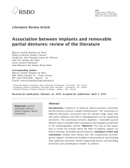
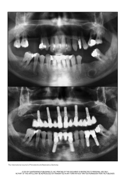
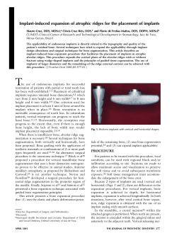
Baixar