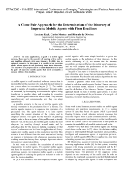
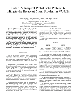
MSC/NASTRAN
Análise Estática de Estruturas
Eliseu Lucena Neto
2014
Introdução
Esperamos que estas notas sejam úteis num primeiro contato do aluno com o programa de
elementos finitos MSC/NASTRAN, utilizando a versão 7.01 do FEMAP. A apresentação
do programa será feito por meio de exemplos envolvendo a análise estática de estruturas.
A MacNeal-Schwendler Corporation, fundada em 1963, pesquisa, desenvolve e dá suporte a softwares CAE (Computer Aided Engineering) ligados à modelagem e análise por
elementos finitos. Participou, junto à NASA (National Aeronautics and Space Administration), no desenvolvimento do programa NASTRAN (NAsa STRuctural ANalysis),
tornando-se cedo proprietária da versão MSC/NASTRAN. A primeira versão comercial
do MSC/NASTRAN é de 1971.
Dentre as áreas de aplicação do MSC/NASTRAN, é a análise estrutural o seu lugarcomum, seguida de aplicações em transferência de calor. Além da evolução natural que
vem sofrendo ao longo dos anos, hoje se acha disponível para computadores que variam
desde os micros até os supercomputadores.
Em linhas gerais, o MSC/NASTRAN realiza:
• Análise Estática Linear : é o tipo de análise mais básica. O termo “linear” significa que a resposta da estrutura — os deslocamentos e as tensões, por exemplo
— é linearmente relacionada com as cargas aplicadas. O termo “estática” significa
que as cargas aplicadas não variam com o tempo — ou que a variação no tempo é
insignificante, podendo ser seguramente ignorada.
• Análise Estática Não-Linear
• Flambagem: faz uso do “problema linearizado no deslocamento” para determinação
da carga crítica (problema de autovalor).
• Análise Modal: calcula as frequências naturais e os correspondentes modos de vibração de uma estrutura (problema de autovalor).
• Análise Harmônica: determina a resposta de uma estrutura quando sujeita a carregamentos que variam harmonicamente com o tempo (carregamentos com frequência definida).
• Análise Dinâmica Transiente: Determina a resposta de uma estrutura quando sujeita a carregamentos que variam arbitrariamente com o tempo. Todas as cargas
aplicadas são conhecidas em qualquer instante.
• Análise Dinâmica Não-Linear
• Transferência de Calor em Regime Estacionário
• Transferência de Calor em Regime Transiente
• Otimização
As variáveis nodais dos elementos utilizados na análise estrutural são “deslocamentos”.
Quantidades como deformação e tensão são derivadas posteriormente.
Elementos
As formas geométricas dos elementos comumente utilizados no MSC/NASTRAN para a
análise estrutural são:
• Elementos unidimensionais: usados em treliças e pórticos.
ROD: resiste a esforço normal e torção; graus de liberdade de um nó no sistema
local: TX (translação na direção de X), RX (rotação em torno de X).
BAR: resiste a todos os esforços; graus de liberdade de um nó no sistema local: TX,
TY, TZ, RX, RY, RZ; prismático.
BEAM: resiste a todos os esforços; graus de liberdade de um nó no sistema local: TX, TY, TZ, RX, RY, RZ; seção transversal variável; o eixo neutro e o de
cisalhamento não precisam coincidir; pode levar em conta o empenamento da seção
transversal na rigidez à torção; etc.
rod element
bar / beam element
axial force, torque,
shear and bending
axial force
and torque only
• Elementos bidimensionais: são triângulos ou quadriláteros planos ou curvos; usados
em membranas, placas e cascas; graus de liberdade de um nó no sistema local: TX,
TY, TZ, RX, RY.
4 noded quadrilateral
6 noded triangle
3 noded triangle
8 noded quadrilateral
• Elementos tridimensionais: são tetraedros, pentaedros e hexaedros; usados em sólidos; graus de liberdade de um nó no sistema local: TX, TY, TZ.
6 or 15 noded PENTA
4 or 10 noded TETRA
8 or 20 noded HEXA
(with and without mid-side nodes)
• Elementos especiais: molas, amortecedores, massas concentradas, etc.
concentrated mass
spring
damper
Aplicações Numéricas
O programa MSC/NASTRAN empregado recorre à versão 7.01 do FEMAP como processador dos dados de entrada e saída dos resultados. Dentre os arquivos criados e deixados
em disco, destacamos:
• xxx.DAT
dados que podem ser executados a qualquer momento.
• xxx.F06
saída de resultados em ASCII.
• xxx.OP2
saída de resultados em binário.
• xxx.MOD
contém a parte gráfica de xxx.DAT. Quando se faz uma execução, podese adicionar em xxx.MOD a saída de resultados (parte gráfica de
xxx.F06 ou xxx.OP2 ).
São apresentados dez exemplos denominados Workshop 1, 2, · · · , 10, sendo o primeiro
deles escrito mais detalhadamente. Alguns foram adaptados da página
http://www.mscsoftware.com ⇒ mechanical solutions ⇒ support ⇒ application examples ⇒ example exercises ⇒ msc.nastran for windows
e outros foram aqui desenvolvidos.
Recomendamos a reprodução de todos os dez exemplos no MSC/NASTRAN, experimentando de próprio punho a potencialidade de um programa dessa natureza. Perceba
como é possível automatizar a análise estrutural e reservar ao engenheiro unica e exclusivamente a parte interpretativa dos resultados. Sobrará assim mais tempo para dedicação
à parte criativa do projeto.
“Who, in practice nowadays, would conduct an elastic analysis of a single-bay
portal frame other than by feeding it into the office program? . . .university
libraries contain shelves of structural textbooks devoted to complex and impenetrable hand-methods for analysing such structures.” (D. A. Nethercot,
“On the Teaching of Structural Engineering”, Proceedings of the Conference on
Civil and Structural Engineering in the 21st Century, University of Southampton, 26—28 April 2000, p. 157).
However, beware of computers. And, especially beware of developers of engineering software. Regardless of the source of trouble, the engineer who uses the software is held
responsible for the results.
Workshop 1
Linear Static Analysis of a
Simply-Supported Truss
Objectives
• Create a finite element model by explicitly defining node locations and element
connectivities.
• Define a MSC/NASTRAN analysis model comprised of rod elements.
• Run a MSC/NASTRAN linear static analysis.
• View analysis results.
1-1
1-2
Workshop 1
Model Description
1500
1300
4
1500
1300
2
1
9
1
1500
3
2
6
5
6
7
8
10
3
4
11
72
7
5
144
192
72
1300
144
96
96
192
Above is a finite element representation of the truss structure shown on the title page.
The nodal coordinates provided are defined in the global cartesian coordinate system
(MSC/NASTRAN Basic System). The structure is comprised of truss segments connected
by smooth pins such that each segment is either in tension or compression. The structure
is pinned at node 1 and supported by a roller at node 7. Point forces are applied at nodes
2, 4 and 6.
Young’s Modulus
1.76 × 10⁶ psi
Poisson’s Ratio
0.3
Cross-Sectional Area 5.25 in2
Workshop 1
1-3
Suggested Exercise Steps
• Define a material.
• Define a rod property using the newly defined material.
• Create the nodes for the truss model in the global cartesian coordinate system.
• Create the truss segments using the newly defined property.
• Define the relevant constraints for the model.
• Create the constraint at node 1 by fixing the 1 and 2 directions (corresponding to
T X and T Y ).
• Create the constraints at node 7 by fixing the T Y direction.
• Apply a −1300 lbf in the F X direction and a −1500 lbf in the F Y direction at
nodes 2, 4 and 6.
• The model is now ready for analysis.
• List the results of the analysis and compare with expected answers at the end of
the exercise.
• Display the deformation of the truss and remove all labels and markers.
Workshop 1
1-4
Exercise Procedure
1. Start up MSC/NASTRAN for Windows 4.5 and begin to create a new model.
Double click on the icon for the MSC/NASTRAN for Windows V4.5.
On the Open Model File form, select New Model.
Turn off the workplane:
Tools / Workplane (or F2) / Draw Workplane / Done
View / Regenerate (or Ctrl G).
Workshop 1
2. Create a material called mat_1.
From the pulldown menu, select Model / Material.
1-5
1-6
Workshop 1
Title
mat_1
Young’s Modulus
1.76e6
Poisson’s Ratio
0.3
Select OK / Cancel.
NOTE: In the Messages Window at the bottom of the screen, you should see a
verification that the material was created. You can check here throughout the
exercise to both verify the completion of operations and to find an explanation for
errors which might occur.
3. Create a property called prop_1 to apply to the members of the truss.
From the pulldown menu, select Model / Property.
Title
prop_1
To select the material, click on the list icon next to the databox and select mat_1.
Material
mat_1
1-7
Workshop 1
Elem / Property Type
Change the property type from Plate element (default) to Rod element.
Line Elements
Select OK.
Rod
1-8
Workshop 1
Area
5.25
Select OK / Cancel.
4. Create the nodes for the truss model.
Create the first node of the model by selecting Model / Node (or Ctrl N).
X:
0
Y:
Z:
0
select OK
0
Repeat the process for the other 6 nodes:
Node
X
Y
Z Select
2
144
72
0
OK
3
192
0
0
OK
4
288 144 0
OK
5
384
0
0
OK
6
432
72
0
OK
7
576
0
0
OK
Select Cancel.
To fit the display onto the screen, select View / Autoscale / Visible (or Ctrl
A)
5. Create the elements for the truss model.
First, display the node numbers:
View / Options / Quick Options (or Ctrl Q) / Labels On / Done / OK.
1-9
Workshop 1
Choose Model / Element (or Ctrl E)
To select the property, click on the list icon next to the databox and select prop_1.
Property
prop_1
When selecting the nodes, you may (if you wish) manually type in the endpoint
nodes of the rod elements. However, it is easier to use the graphic interface and
select the nodes on the screen using the mouse. Click in the first Nodes box and
then select the nodes on the screen in the following order.
NOTE: The node nearest to the cursor is highlighted by a large yellow X - you don’t
have to click precisely on the node!
Nodes: 1
2
select OK
Element 1 has now been created between the two nodes. Continue creating the rest
of the elements by connecting the following nodes:
1-10
Workshop 1
Nodes Select
2
4
OK
4
6
OK
6
7
OK
2
3
OK
3
4
OK
4
5
OK
5
6
OK
1
3
OK
3
5
OK
5
7
OK
Select Cancel.
6. Create the model constraints.
Before creating the appropriate constraints, a constraint set needs to be created.
Do so by performing the following:
Model / Constraint / Set
Title
Select OK.
constraint_1
Workshop 1
1-11
Now, define the relevant constraint for the model.
Model / Constraint / Nodal
Select Node 1. It will be marked with a white circle, a +1 will be added to the
Entity Selection box, and you will be unable to highligh it anymore. These are all
ways of checking which node you have selected.
Select OK.
1-12
Workshop 1
On the DOF box, select
TX
TY
Select OK.
Notice that the constraint appears on the screen at Node 1, fixing the 1 and 2
directions (corresponding to TX and TY). Create the constraint for the other side
of the model.
Select Node 7 / OK
On the DOF box, select
TY
Select OK / Cancel.
7. Create the model loading.
Like the constraints, a load set must first be created before creating the appropriate
model loading.
1-13
Workshop 1
Model / Load / Set (or Ctrl F2)
Title
load_1
Select OK.
Now, define the relevant loading conditions.
1-14
Workshop 1
Model / Load / Nodal
Select Nodes 2, 4 and 6 / OK
Highlight Force
Method
Load
Constant
FX
-1300
FY
-1500
Select OK / Cancel.
Notice that the component forces are combined. To view the component:
1-15
Workshop 1
View / Options (or F6)
Options
Load Vectors
Vector Length
Scale by Magnitude
Options
Load-Force
Color / Component Mode
Entity, Components
Select OK.
1-16
Workshop 1
8. Submit the model for analysis.
File / Analyze
Analysis Type
Static
Loads
load_1
Constraints
constraint_1
Run Analysis
Select OK.
When asked if you wish to save the model, respond Yes.
1-17
Workshop 1
Be sure to set the desirable working directory.
File Name
work_1
Select Save.
When the MSC/ NASTRAN manager is through running, MSC/ NASTRAN for
Windows will be restored on your screen, and the Message Review form will appear. To read the messages, you could select Show Details. Since the analysis ran
smoothly, we will not bother with the details this time. Then, select Continue.
9. List the results of the analysis.
To list the results, select the following:
List / Output / Unformatted
Select All / OK
1-18
Workshop 1
NOTE: You may want to expand the message box in order to view the results.
Select OK.
Answer the following questions using the results. The answers are listed at the end
of the exercise.
When there is a big list of results, a quick way to determine the results at a specified
node or element is using the List/ Output/ Query command. The step required
to answer the first question is listed below.
List / Output / Query
Output Set
MSC / NASTRAN Case 1
Category
Any Output
Entity
Node
ID
7
Select OK.
Double click at the bottom of the screen to see the results. Double click again to
return.
What is the displacement at grid (node) 7?
Disp. X =
Disp. Y =
Disp. Z =
Workshop 1
1-19
What is the constraint force at grid (node) 1?
Force X =
Force Y =
Force Z =
What is the axial stress for element 7?
Axial Stress =
10. Display the deformed plot on the screen.
Finally, you may now display the deformed plot. First, however, you may want to
remove the load and boundary constraint markers.
View / Options / Quick Options (or Ctrl Q)
Force / Constraint / Done / OK
1-20
Workshop 1
Plot the deformation of the truss.
View/ Select (or F5)
Deformed Style
Deform
Select Deformed and Contour Data / OK / OK.
This concludes the exercise.
File / Save
File / Exit.
1-21
Workshop 1
Answer
node 7
node 1
disp. X disp. Y
disp. Z force X force Y
0.12779
0
0
3900
2900
element 7
force Z axial stress
0
369.14
Baixar