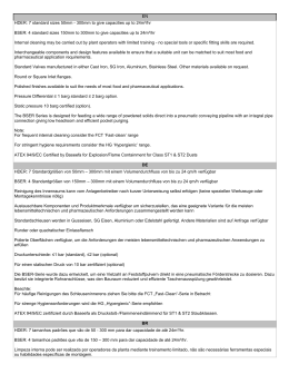
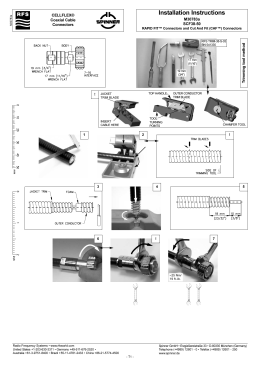
PY X-S-05 - Blitzleuchte
Betriebs- und Montageanleitung
Maße
109.6 [4.31]
98 [3.86]
50 [1.97"]
13
[0.51"]
80.6 [3.17]
60
[2.36"]
35.4
[1.39"]
85.8 [3.38]
Ø6.3 [0.25]
25.3
[1"]
Kartoninhalt:
1x Alarmgerät
1x Membrannippel M20
1x Betriebsanleitung
1x Widerstand (nur –SSM)
26.8 [1.06"]
37 [1.46"]
22 [0.87"]
M20-Ausbruch
vorbereitet
35.4
44.1 [1.74"] [1.39"]
Bohrbild im Inneren
des Gehäuses
Technische Daten
Blitzenergie
5J
Effektive Nennlichtstärke
44 cd (klar)
Blitzfolgefrequenz
1Hz
12 V DC
24V DC
48V DC
24V AC
50/60 Hz
115 V AC
50/60 Hz
230V AC
50/60 Hz
10 –15 V DC
18 – 30 V DC
40 – 57V DC
18 – 30V AC
95 - 127 V AC
195– 253 V AC
650 mA
350 mA
170 mA
800 mA
120 mA
90mA
7,5 W
9,5 W
7,5 W
30 VA
14,5 VA
21,5 VA
Bemessungsspannung
Spannungsbereich
Stromaufnahme (max)
Leistungsaufnahme
Einschaltdauer
100%
Anschlussklemmen
0,14 - 2,5mm² feindrähtig / AWG24 - AWG 14 (stranded)
Schutzart
IP66 (EN60529) , Type 4 & 4x
Schutzklasse
II
Betriebstemperatur
-40°C…+55°C
Lagertemperatur
-40°C…+70°C
Max. rel. Luftfeuchte
90%
Kabeleinführung
Dichtbereich der
Durchführungstülle
Gehäusematerial
7 – 13 mm
4x M20 vorgeprägt
- Bei Verwendung von Kabeldurchmessern < 7 mm ist eine Kabelverschraubung mit
ausreichender Schutzart vorzusehen
PC/ABS Blend
Haubenmaterial
PC
Einbaulage
beliebig
Optionen
-SSM, (siehe Seite 2)
Zubehör
Plombierstopfen (Art.-Nr. 28300000002)
Haubenfarben
klar, weiß, gelb, orange, rot, grün, blau
Zulassungen
Zulassungen (gilt für gekennzeichnete Betriebsmittel)
Bauproduktrichtlinie
(89/106/EWG)
VdS 0786-CPD-21219
Optionen
Bemessungsspannung
Spannungsbereich gemäß EN54-23
Haubenfarbe
Signalisierungsbereich
Umweltschutzklasse
–SSM (nur 24V DC)
24V DC
18V – 30V
48V DC
40 – 57V DC
rot, klar
EN 54-23 Kategorie O:
siehe Dokument 30320-005-1
Typ B
Einbaulage
siehe Dokument 30320-005-1
Die Prüfung erfolgte unter Verwendung des mitgelieferten Membrannippels und der äußeren
Befestigungsbohrungen.
VdS
G212186, Daten siehe Bauproduktenrichtlinie (89/106/EWG)
GL
GLxxxxx (in Vorbereitung)
Umweltkategorie C, H, EMC1
UL, cUL
UEES, UEES7 (weiterführende Informationen siehe Seite 3)
985 501 003
1
Inbetriebnahme
Sicherheitshinweise:
- Der elektrische Anschluss darf nur von hierfür autorisierten Personen in Übereinstimmung mit den derzeit gültigen
Vorschriften durchgeführt werden.
- Warnung vor gefährlicher hoher elektrischer Spannung.
- Vor dem Öffnen ist sicherzustellen, dass das Gerät nicht unter Spannung steht.
- Vor Inbetriebnahme ist die auf dem Typenschild angegebene Versorgungsspannung zu kontrollieren. Eine falsche
Betriebsspannung kann zur Schädigung bzw. zur Zerstörung des Betriebsmittels führen.
- Bei der Installation ist darauf zu achten, dass die Anschlussleitung gegen Zug und Verdrehen abgesichert ist.
Bitte beachten: Die Geräte sind nicht für einen ortsveränderlichen Einsatz bestimmt.
- WARNUNG: Bei Installation Verdrahtung entfernt von scharfen Kanten, Ecken und internen Komponenten.
- Die Funktion des Gerätes ist nur gewährleistet, wenn Ober- und Unterteil korrekt zusammengefügt sind.
- Um eine Beeinträchtigung des Sehvermögens zu verhindern, ist der dauernde, direkte Blick in die aktivierte Leuchte zu
vermeiden.
Öffnen des Gehäuses:
1.
Verschließen des Gehäuses
2.
3/8
1.
Durch Lösen der vier
Deckelschrauben lässt
sich das Oberteil
abnehmen
2.
3/8
Verschließen des Gehäuses
durch Drehen der
Deckelschrauben in die
Endstellung bis zur
Verrastung.
Das Gerät wird in nicht verschlossenem Zustand ausgeliefert.
Plombierstopfen für die Gehäuseschrauben sind als Zubehör erhältlich.
Elektrischer Anschluss:
Anschlussplatine
im Unterteil
X1
Betriebsspannungsanschluss
N
L
+
Option –SSM (Soft-Start-Modul) (nur 24V DC):
- Begrenzung der Einschaltstromspitze auf max. 2,1A
- Durchschalten der Betriebsspannung zum Betriebsmittel erst ab >7V
- Widerstand zur Leitungsüberwachung angeschlossen.
Betriebsspannungsbereich: 18V – 30V DC
Anschluss eines Widerstandes
zur Leitungsüberwachung:
Widerstand für Leitungsüberwachung (1KOhm)
am Betriebsspannungsanschluss.
Position des Widerstandes bei Parallelschaltung
von mehreren Leuchten im letzten Gerät.
Nicht benötigte Widerstände entfernen.
X1
Kabeldurchführungen
Zur Sicherstellung der angegebenen Schutzart sind
an den dafür vorgesehenen Durchbrüchen
Kabeldurchführungen mit einer Schutzart von IP 66
zu montieren. Der mitgelieferte Membrannippel
kann durch eine Kabelverschraubung oder durch
einen M12-Steckverbinder mit einem Flanschmaß
von M20 ersetzt werden.
Membrannippel IP 66
(mitgeliefert)
Nach Montage des Kabels
Reste der Membrane entfernen.
Kabelverschraubung
IP 66
M12- Steckverbinder IP 66
(für Kleinspannungs-Geräte)
Wartung, Service, Instandhaltung
Das Gerät erfordert keine besondere Wartung. Die äußere Reinigung sollte mit einer schwachen Seifenlösung ohne
Verwendung von Lösungsmittel erfolgen.
Die Blitzleuchte darf nur in unbeschädigtem Zustand innerhalb der spezifizierten Kenndaten betrieben werden. Umbauten,
Änderungen, fehlerhafter und unzulässiger Einsatz sowie die Nichtbeachtung der Hinweise dieser Betriebsanleitung
schließen eine Gewährleistung aus.
Ein Austausch von Komponenten darf nur mit Originalersatzteilen erfolgen. Reparaturen sind grundsätzlich im
Herstellerwerk auszuführen.
985 501 003
2
PY X-S-05 – Beacon
Operating and installation instruction
109.6 [4.31]
98 [3.86]
50 [1.97"]
37 [1.46"]
35.4
[1.39"]
60
[2.36"]
25.3
[1"]
80.6 [3.17]
85.8 [3.38]
Ø6.3 [0.25]
Content of package:
1x Alarm device
1x Diaphragm nipple M20
1x Operating instruction
1x Resistor (only –SSM)
13
[0.51"]
Dimensions
26.8 [1.06"]
35.4
44.1 [1.74"] [1.39"]
Hole pattern in the
inside of housing
22 [0.87"]
prepared
M20 piercing
Technical Data
Flash energy
Rated effective luminous
intensity
Flash frequency
5J
44 cd (clear)
1Hz
12 V DC
24V DC
48V DC
24V AC
50/60 Hz
10 –15 V DC
18 – 30 V DC
40 – 57 V DC
18 – 30 V AC
Current consumption
(max)
650 mA
350 mA
170 mA
800 mA
120 mA
90mA
Power consumption
7,5 W
9,5 W
7,5 W
30 VA
14,5 VA
21,5 VA
Rated voltage
Operating voltage range
Duty cycle
Connection terminal
Protection system
115 V AC, 50/60
230V AC
Hz
50/60 Hz
95 - 127
195 – 253 V AC
V AC
100%
0,14 - 2,5mm² / AWG24 - AWG 14 (stranded)
IP66 (EN60529), Type 4 & 4x
Protection class
II
Double insulated equipment
-40°C…+55°C
-40°C…+70°C
90%
4x M20 (prepared)
7 – 13 mm
With the use of cable diameters <7 mm, a cable screw joint
with sufficient ingress protection must be provided
PC/ABS Blend
PC
arbitrary
-SSM (see page 4)
Sealing plug (Art-no. 28300000002)
clear, white, yellow, amber, red, green, blue
Operating temperature
Storage temperature
Max. rel. Humidity
Cable entry
Sealing range of
grommet
Material of housing
Material of lens
Installation position
Options
Accessory
Lens colours
Approvals
Approvals (valid for marked equipment)
Construction Product
Directive
(89/106/EWG)
VdS 0786-CPD-21219
Options
Rated voltage
Operating voltage range
acc. to EN54-23
Lens colours
Signalling area
Environmental
protection class
Installation position
–SSM (24V DC only)
24V DC
48V DC
18V – 30V
40 – 57V DC
red, clear
EN 54-23 Category O: see document 30320-005-1
Type B
see document 30303-005-1
The test was performed using the provided diaphragm nipples and the outer fixing holes.
VdS
G212186, data see Construction Product Directive (89/106/EWG)
GL
GLxxxxx (in preparation)
UL, cUL
UEES, UEES7
“General Signaling Equipment” Suitable for indoor and outdoor use.
Warning: Not to be used as a Visual Public Mode Alarm Notification Appliance.
Directional characteristics on effective luminous intensity see document 30320-005-1.
985 501 003
Environmental Category C, H, EMC1
3
Taking into operation
Safety notes:
- Installation must be carried out by an electrician in compliance with the latest codes and regulations.
- Danger: High voltage may be present.
- Prior to opening, it must be ensured that no voltage is applied to the device.
- Before electrical connection, the supply voltage on the type plate is to be checked. The wrong operating voltage can
lead to damages or to the destruction of the equipment.
- During installation it must be ensured that the connection cables are secured against tension and distortion.
Please observe: The devices are not designed for portable use.
- CAUTION: When making installation, route field wiring away from sharp projections, corners and internal
components.
- The function of the unit is only guaranteed if the upper and lower section is joined correctly.
- In order to prevent detriment to sight, continuously looking directly in the activated light is to be avoided.
Opening the housing
1.
Closing the housing
2.
By loosing the four cover
screws, the upper section
can be removed.
3/8
1.
2.
3/8
The housing is closed by
turning the cover screws to
the limit position until the
housing locks into place.
The unit is not closed when delivered.
Sealing plugs for the housing screws are available as accessories.
Electrical connection:
Circuit board for electrical
connection (located in the
base section):
Connecting cables:
7 [0.28"]
7 [0.28"]
solid
N
Connection for
Operating voltage
L
+
stranded
Option –SSM (Soft-Start-Module) (24V DC only):
- Limiting of the switch-on current peak to max. 2.1A
- Connection of the operating voltage to the equipment starts at >7V
- Resistance for the line monitoring connected.
Operating voltage range: 18V – 30V DC
Connection of a resistor
for line monitoring:
Resistor for line monitoring (1KOhm) at terminal for operating voltage
Position of resistor in last device when using several beacons in parallel
Remove resistors that are not needed
X1
Cable gland entries
To guarantee the specified protection type,
cable grommets with a protection type of IP 66
are to be installed at the openings provided for
this purpose. The supplied diaphragm nipple
can be replaced with a cable gland or with an
M12 plug connection with a flange
measurement of M20.
Diaphragm nipple IP 66
Cable gland IP 66
(provided)
After pushing through the cable remove
the remaining membrane break-out.
M12 plug connector IP 66
(for low voltage versions)
Maintenance, Service and Ordering Spare Parts
The device does not require any special maintenance. External cleaning should be done with a mild soap solution
without the use of solvents. The device may only be operated in the undamaged state within the specified rating.
Conversions, alterations, improper and inadmissible use as well as the non-observance of the notes in these
operating instructions shall render the warranty null and void.
Components may be replaced only by original spare parts. As a matter of principle, repairs are to be carried out in the
manufacturing works.
985 501 003
4
PY X-S-05 - Luz estroboscópica
Manual de Operação e de Instalação
Dimensões
13
[0.51"]
50 [1.97"]
35.4
[1.39"]
60
[2.36"]
25.3
[1"]
Conteúdo da caixa:
1 dispositivo de alarme
1 bico de membrana M20
1 Manual de Operação
1 resistência (só -SSM)
26.8 [1.06"]
35.4
44.1 [1.74"] [1.39"]
Recorte M20
preparado
Diagrama de
perfuração no
interior da carcaça
Dados técnicos
Energia de flash
5J
Luminosidade nominal efetiva
44 cd (claro)
Freqüência de intermitência
1 Hz
Tensão nominal
12 V CC
Gama de tensão
10 –15 V CC
Consumo de corrente (máx.)
Consumo de potência
24 V CC
48 V CC
18 – 30 V CC 40 – 57 V CC
24 V CA
50/60 Hz
115 V CA
50/60 Hz
230 V CA
50/60 Hz
195– 253 V CA
18 – 30V CA
95 - 127 V CA
650 mA
350 mA
170 mA
800 mA
120 mA
90 mA
7,5 W
9,5 W
7,5 W
30 VA
14,5 VA
21,5 VA
Ciclo operacional
100%
Terminais de conexão
0,14 - 2,5mm² fios finos / AWG24 - AWG 14 (entrançado)
Grau de proteção
IP66 (EN60529) , tipo 4 & 4x
Classe de proteção
II
Temperatura operacional
-40°C…+55°C
Temperatura de armazenamento
-40°C…+70°C
Umidade relativa máx.
90%
Entrada de cabo
Área de vedação do perfil de
proteção
Material da carcaça
7 – 13 mm
4x M20 pré-cunhada
- Ao usar um diâmetro de cabo inferior a 7 mm deve prever um prensa-cabos com
grau de proteção adequada
Mistura de PC/ABS
Material da cobertura
PC
Posição de instalação
qualquer
Opções
-SSM, (ver página 2)
Acessórios
Bujão de chumbar (N° do art. 28300000002)
Cores da cobertura
claro, branco, amarelo, cor de laranja, vermelho, verde, azul
Aprovações
Aprovações (é válido para dispositivos operacionais marcados)
Diretriz relativa aos
produtos de
construção
(89/106/CEE)
VdS 0786-CPD-21219
Opções
Tensão nominal
Gama de tensão de acordo com a
norma EN54-23
Cor da cobertura
–SSM (só 24V CC)
24 V CC
48 V CC
18 V – 30 V
40 – 57 V CC
Classe de proteção ambiental
vermelho, claro
EN 54-23 Categoria O:
ver documento 30320-005-1
Tipo B
Posição de instalação
ver documento 30320-005-1
Área de sinalização
O ensaio foi realizado usando o bico de membrana fornecido e os furos de fixação externos.
VdS
G212186, dados ver Diretriz relativa aos produtos de construção (89/106/CEE)
GL
GLxxxxx (em preparação)
Categoria ambiental C, H, EMC1
UL, cUL
UEES, UEES7 (para mais informações, ver página 3)
985 501 003
5
Colocação em funcionamento
Instruções de segurança:
- A conexão elétrica só pode ser efetuada por pessoas autorizadas para tal em conformidade com os regulamentos
atualmente em vigor.
- Aviso quanto a elevada tensão elétrica perigosa.
- Certifique-se antes da abertura de que o aparelho não está sob tensão.
- Controle antes da colocação em funcionamento a tensão de alimentação indicada na placa de características. Uma tensão
de operação incorreta pode causar danos ou destruir os dispositivos operacionais.
- Na instalação preste atenção para que o cabo de ligação esteja protegido contra tração e entrançamento.
Observe: Os aparelhos não são destinados para um uso portátil.
- AVISO: Ao instalar, coloque a cablagem longe de arestas, cantos e componentes internos afiados.
- O funcionamento do aparelho só é garantido se a parte superior e a inferior forem corretamente ajuntadas.
- Para evitar uma perturbação da visão, deve-se evitar a visualização contínua e direta da luz ativada.
Abrir a carcaça:
1.
3/8
Fechar a carcaça
2.
1.
Mediante
desaparafusamento dos
quatro parafusos da
tampa pode-se retirar a
parte superior
2.
Feche a carcaça rodando os
parafusos da tampa para a
posição final até ao engate.
3/8
O aparelho é fornecido em estado não fechado.
Os bujões de chumbar para os parafusos da carcaça estão disponíveis como acessório.
Conexão elétrica:
Placa de conexão
na parte inferior
X1
Conexão
Betriebsspannungsda tensão
deanschluss
operação
N
L
+
Opção –SSM (Soft Start Module/módulo de arranque suave) (só 24 V CC):
- Limitação do pico de corrente inicial em, no máx., 2,1 A
- Comutação da tensão de operação para o dispositivo operacional só a partir de > 7 V
- Resistência ao monitoramento do cabo conectada.
Gama da tensão de operação: 18 V – 30 V CC
Conexão de uma resistência
ao monitoramento do cabo:
diversos luzes estroboscópicas no último aparelho.
Passagens de cabo
Para garantir o tipo de proteção indicado, deve-se
montar passagens de cabo nas aberturas previstas
com grau de proteção IP 66. O bico de membrana
fornecido pode ser substituído por uma prensacabos ou por um conector M12 com uma medida
de flange de M20.
Bico de membrana IP 66
(fornecido junto)
Após a montagem do cabo
remover os restos da membrana
Prensa-cabos
IP 66
Conetor M12 IP 66
(para aparelhos de baixa tensão)
Manutenção, Assistência, Reparo
O aparelho não necessita de manutenção especial. A limpeza externa deve ser efetuada com uma solução de sabão suave
sem usar solventes.
A luz estroboscópica só pode ser operada em estado intacto dentro dos dados característicos especificados. Reconstruções,
modificações, uso incorreto e não autorizado, bem como o não cumprimento das instruções deste Manual de Operação
anulam a garantia.
Uma troca de componentes só pode ser efetuada com peças de reposição originais. Reparos devem ser efetuados
exclusivamente na fábrica do fabricante.
985 501 003
6
Pfannenberg GmbH
Werner-Witt-Straße 1 · D- 21035 Hamburg
Tel.: +49/ (0)40/ 734 12-0 · Fax: +49/ (0)40/ 734 12-101
technical.support @pfannenberg.com
http://www.pfannenberg.com
985 501 003
05/2013
985501903
7
Baixar