A Wireless Sensors Suite for Smart Grid Applications
António Grilo1, Helena Sarmento1, Mário Nunes1, José Gonçalves 2, Paulo Pereira1,
Augusto Casaca1, Carlos Fortunato3
1
INESC-ID/IST/TULisbon, Portugal
{Antonio.Grilo, Helena.Sarmento, Mario.Nunes, Paulo.Pereira, Augusto.Casaca}@inesc-id.pt
2
INOV, Portugal
[email protected]
3
EDP – Energias de Portugal, Portugal
[email protected]
Abstract. This paper presents a demonstrator of a Wireless Sensor and Actuator Network (WSAN) for Smart Grid applications, developed in the context of
project WSAN4CIP. This WSAN is formed by WSAN nodes equipped with
sensors and a wireless radio interface, which monitor key parameters of power
grid equipments belonging to the Medium Voltage (MV) and Low Voltage
(LV) segments. The measurements are reported to the SCADA system and constitute the basis of both safety and security services to improve the power grid
distribution dependability. This paper describes the hardware of the sensor
nodes and presents the respective performance results, attesting the feasibility
of the proposed solutions.
Keywords: Smart Grid, WSAN, Sensor, Energy Harvesting
1
Introduction
The Smart Grid (SG) is an emerging concept where information technologies are
used to provide embedded intelligence to the electrical grid, encompassing all of the
latter’s segments: power generation, electricity transmission, electricity distribution
and consumption. According to this concept, the SG will have such capabilities as to
integrate micro producers of energy (possibly coinciding with customers), to perform
automatic fault detection and self-reconfiguration according to supply and demand
patterns. In order to allow these advanced functionalities, the power grid must first be
sensorized, i.e. fit with sensors that are able to collect and deliver relevant measurements to the processing systems, as well as electro-mechanical actuators that are used
to change the configuration of the grid.
The SG is expected to gradually evolve from the legacy power grid. At the current
stage, the deployment of extra technology can already improve the latter’s dependability. For example, monitoring of power system parameters in the transmission and
distribution segments, such as voltage, current and equipment temperature, as well as
monitoring and control of substation devices is crucial for the efficient operation of
the power grid, namely regarding early detection of fault conditions [1]. Wired com-
munication could be used, but wireless technologies usually constitute a less expensive option. The use of wireless sensors and actuators can also lead to a more powerful and efficient solution due to the deployment flexibility, besides avoiding the deployment of cables in already cluttered power grid facilities [2].
The FP7 project WSAN4CIP1 has selected the power grid distribution segment as the
specific target for one of its two demonstrators. This segment receives High Voltage
(HV) lines from the transport segment of the grid, delivering Low Voltage (LV) and
Medium Voltage (MV) lines to customer premises. It mainly consists of HV/MV
substations, connected by MV power lines to industrial customers or secondary substations (where MV is converted to LV), as well as the LV power lines connected to
LV customers. A SCADA system is used as a supervisory control and data acquisition
system for this infrastructure.
This paper presents a demonstrator developed within the scope of the WSAN4CIP
project, which addressed the protection of critical infrastructures through the use of
Wireless Sensor and Actuator Networks (WSAN). The demonstrator includes sensor
nodes developed within the project. This paper focuses the hardware of the sensor
nodes and presents the respective performance results, attesting the feasibility of the
proposed solutions. The detailed description of the WSAN architecture is presented in
another paper [3].
The rest of this paper is organized as follows. Section 2 presents and overview of
the WSAN demonstrator. The deployed sensor node hardware is described in detail in
Section 3. The sensor performance results are presented in Section 4. Finally, Section
5 concludes the paper.
2
WSAN demonstrator overview
The WSAN4CIP project focused on improving the dependability of critical infrastructures. This demonstrator was intended to validate the research done for the specific case of the power grid distribution system.
A proof-of-concept demonstrator was deployed at EDP Distribuição2 premises,
more precisely at the São Sebastião primary substation, located in the neighborhood
of the city of Setúbal, in the west of Portugal. The São Sebastião substation provides
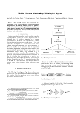
electric energy to the Setúbal region. Fig. 1 sketches the WSAN demonstrated in
WSAN4CIP, where wireless sensor nodes and their links are also represented.
The power grid distribution infrastructure mainly consists of a set of substations,
MV power lines connecting substations to Medium Voltage/Low Voltage (MV/LV)
power transformers residing in the secondary substations and LV power lines from
the secondary substations to the customers. Some industrial customers may also get
direct MV power lines. Associated to this infrastructure we consider also the SCADA
system, which is a supervisory control and data acquisition system dedicated to the
1
Wireless Sensor and Actuator Networks for the Protection of Critical Infrastructures
http://www.wsan4cip.eu/
2
EDP Distribuição is the main company that carries out the function of electricity distribution
operator in mainland Portugal.
infrastructure. Remote surveillance of the power grid is already done to some extent
based on wired sensors. The use of wireless sensors can, however, lead to a more
flexible and powerful protection scenario for the substations, power lines and power
transformers. The deployment flexibility of WSAN allows capturing more status parameters than the currently deployed wired sensors and the wireless nature of the
communication can contribute to avoid critical points of failure.
Secondary Substation
Substation 60/30/15 kV
15 KV
...
WSAN4CIP Node
SCADA/WSAN Gateway
400V /
230V
Radio Link
400V /
230V
400V /
230V
Fig. 1. WSAN for the electrical distribution segment of the power grid.
In the WSAN4CIP project we focused into improving the dependability of the
substation components, MV and LV power lines, and MV/LV power transformers in
the secondary substations. We have defined solutions for the remote active monitoring of: i) substation circuit breaker trip coil status; ii) temperature of the substation
power transformer oil, substation neutral reactance oil and substation neutral resistor
coil box; iii) MV and LV power line current activity; iv) MV/LV power transformer
hotspot detection; v) human activity in the secondary substation through the use of
movement detectors and video cameras. All the monitored parameters and images are
visualized at the SCADA system, through a special-purpose graphical user interface.
The requirement for video transmission and the long distances between MV power
line towers place additional requirements in terms of the communications and processing capabilities of the WSAN nodes, prompting the use of a broadband mediumrange technology such as IEEE 802.11g for WSAN communications.
3
Wireless Sensor Nodes
Wireless sensor nodes include the sensor with the conditioning electronics, an
IEEE 802.11g module, a DC-DC converter and an external power supply.
WSAN4CIP has integrated two solutions: one based on a Silex SX-560 core3 and a
second solution based on a Beagleboard4. While video compression at the secondary
substation requires a more powerful processing node such as the Beagle, scalar sensor
3
4
http://www.silexeurope.com/en/home/products/wireless-modules/sx-560.html
http://beagleboard.org/
nodes can be based on a less powerful board such as the Silex SX-560 that requires
less energy to operate (an energy analysis of the SX-560 is presented in [4]). The
Beagleboard is also able to support a secure operating system. The inclusion of two
different solutions allows also the demonstration of a heterogeneous scenario.
Sensor node PCBs integrating the Silex SX-560 SOC were developed at INOV.
The external power supply is either MV power-line energy harvesting or 230 V AC,
depending on the node. Conditioning electronics depend on the sensor type. Next
subsections describe the hardware of the sensors for current intensity measurement,
temperature measurement, and circuit breaker status detection.
3.1
MV current sensing node with energy harvesting
The MV and LV power line scenarios aim to monitor the status of particular power
line sections. It is therefore possible to know centrally the location of a power line
failure. The chosen MV power line has a voltage of 15kV and feeds a set of MV/LV
power transformers in secondary substations. The line topology is a tree shape with
several leaves consisting of secondary substations (see Fig. 1). The physical measurement to be done is the electrical current flowing through the line; a current transformer is used to measure its value and to derive a parasitic power source for the
wireless sensor, reducing the power constrains on the wireless protocols through this
energy harvesting technique. The current sensor samples the current on the line every
second. This section describes the MV sensor only. The LV sensor is similar, but
sensor nodes are in this case attached to public lamps, being fed directly from the
monitored AC power line.
The electrical current flowing through each line (phase) is sensed and measured,
using a current transformer (CT). The current to charge the battery is also obtained
from the MV line, using the same current CT. Therefore, two working modes are
defined for this WSN node: current sensing and energy harvesting. In the current
sensing mode, the current in the line is estimated based on the current passing in the
secondary winding of the transformer. The harvesting mode uses the secondary current to charge the battery. Modes are controlled by the microcontroller of the wireless
module.
Fig. 2 depicts the block diagram of the circuit that implements the conditioning
electronics and the energy harvesting from the line.
A CT is an instrument transformer intended to have its primary winding connected
in series with the conductor carrying the current to be measured or controlled. In a
window type CT, the secondary winding is insulated from and permanently assembled on the core, but no primary winding exists as an integral part of the structure.
Primary insulation is provided in the window, through which one turn of the line conductor can be passed to provide the primary winding. A large current in the primary
winding is reduced to a lower level to be more easily measured. The number of secondary turns determines the amplitude of the output current.
The used CT is a split core CT that can be temporarily opened to be place around
existing wires, without disconnecting the primary circuit. Other specifications are:
minimal current value in the line is 5A; maximal current value is 300 A; and accuracy
in current measurements up to 10%.
Fig. 2. Electronic circuit for current sensing and energy harvesting
The Hobut CTS80-15, with a ratio of 400/5 was selected. It supports a primary current up to 400A. This CT is suitable for three classes of accuracy: 0.5% up to 2.5 VA;
1% up to 6 VA; and 3% up to 10 VA, being adequate to the specifications for current
measurement accuracy (10%).
The GPIO_4 signal (Fig. 2), from the microcontroller in the Silex SX-560 module,
controls the energy harvesting and sensing modes. It switches on/off a NMOS transistor in the Current Monitoring module. When the transistor is switched on, the sensing
mode is on and it avoids current to pass to the battery circuit. The voltage at A/D1 is
converted by an ADC and sent to the microcontroller. It represents the secondary
current, permitting to determine the current in the MV power line.
The transistor is switched off in the energy harvesting mode, when the current is
allowed to flow to the battery. The battery charge can be monitored, reading VBat
that is connected to an input port of the ADC.
The ADC (ADC122S021) is a two-channel 12-bit successive-approximation ADC
converter, suitable for sensing applications, with a serial interface compatible with the
Serial Peripheral Interface (SPI) of the SX-560.
The electronic circuit is enclosed in an aluminum alloy box with a cubic shape
(Fig. 3). The aluminum box is completely covered with a Scotch™ 23 Electrical tape,
a highly conformable Ethylene Propylene Rubber (EPR) based, high voltage splicing
tape. It is a non-vulcanizing, shelf-stable tape with excellent electrical properties.
Tape can be used as insulation for low-voltage applications as well as insulation for
splices up to 69kV.
To guarantee high resistance to outdoor weather conditions, namely to humidity,
rain and UV rays, the box is then painted with liquid silicon. This node was designed
as to be suspended on a 15 kV aerial power line (Fig. 3).
5
6.
http://www.hobut.co.uk/current-transformers/split-core-cts/series-80U
Fig. 3. MV power line current sensing wireless node.
3.2
Trip coil sensor and actuator
The trip coil is the component of the circuit breaker that permits to interrupt the electrical current flow, by applying 110 V at its terminals. After the activation of the circuit breaker, the coil can be damaged. A sensor and an actuator periodically evaluate
the operating status of the circuit breaker. In order to verify the status of circuit breaker status, a 5 V DC voltage is applied every 60 minute by an actuator. If there is current flow, the coil is working properly.
To verify the existence of a current flow, a magnetic sensor is used. The selected
sensor (KMZ10C) is a magnetic field sensor, employing the magneto-resistive effect
of thin-film permalloy. Four sensors, connected in a Wheatstone bridge configuration,
define the complete sensor. Conditioning electronics includes an instrumentation
amplifier (MAX4208) with adjustable gain defined by two external resistors. The
analog amplified voltage is converted to a digital value by an ADC that includes an
internal sample and hold circuit. The digital signal is connected to the microcontroller
of the Silex SX-560 Module by an SPI interface. As the 110 V DC voltage can be
simultaneously applied to the coil terminals, a optocoupler is used to provide electrical isolation.
3.3
Temperature sensors
At the distribution substation, failures in power transformers affect a series of power
lines and all the downstream secondary substations, resulting in problems for homes
and businesses. Some failures can be detected just by monitoring the oil temperature
of the 15 kV power transformers. The Neutral Reactance oil tank and Neutral Resistor
coil box temperatures are also monitored as a means for failure detection. Their temperature can significantly rise during phase-earth failures during which these devices
have to dissipate very high currents while the power line connectivity is not interrupted by the circuit breakers.
The selected sensor (LM70) is a silicon temperature sensor, detecting the voltage
change across a pn junction. Temperature resolution is 0.25°C while operating over a
temperature range of −55°C to +150°C. Depending on the temperature range, accuracy changes from ±2° up to +3.5/−2°C. The LM70 is an integrated circuit, including
the temperature-sensing element, the signal conditioning electronics, an ADC con-
verter and the SPI serial data link. Therefore, it connects directly to the microcontroller of the Silex SX-560 module.
3.4
Video Surveillance, Intrusion and Hotspot Detector
This WSAN node is the result of mixing different technologies, all interconnected
to a Beagleboard WSAN node:
Video surveillance: Logitech’s Quickcam Sphere AF Webcam connected through a
USB interface. To ensure the goal in harsh illumination conditions, it was implemented a small device of illumination composed by a light-emitting diode (LED)
device controlled through GPIO;
Motion detection: passive infrared (PIR) sensor communicating through GPIO;
Hotspot detector: IRISYS IRI 1011 Thermal Infrared Camera communicating
through a RS232 serial data link. Due to unavailable RS-232 ports on the
Beagleboard, the interface with the Thermal Camera was made with a RS-232 to
USB adapter.
4
Tests and results
The current sensor was tested separately at special lab facilities before the WSAN
integrated tests and trial deployment. This was due to the harsh electromagnetic conditions to which it would be subject during the trial, as well as the high costs of retrieval and redeployment. The other sensors were tested both in lab and in situ, i.e.
already coupled with the monitored equipments. This section will cover the individual
sensor performance tests. The integrated WSAN performance tests are described in
another paper [1].
4.1
MV current sensing node
In order to find potential EMC (ElectroMagnetic Compatibility) problems, the
wireless current sensor node was tested under exposure to the electromagnetic fields
generated by the 15 kV power line. Fig. 4 presents the testing environment. Firstly,
the node behavior was tested for voltages of 9kV, 13 kV and 20 kV. No problems
were detected on the wireless communication or on the node functionality. Only for
20 kV, the corona effect [5] starts to be noticed.
Fig. 4. High Voltage Tests
measured current [A]
Accuracy was also analyzed in the MV environment. Results are depicted in Fig. 5.
Measured values present an offset to the theoretical values. Calibration was then done
by software.
180
160
140
120
100
80
60
40
20
0
0
20
40
60
80
100
120
140
160
Line current [A]
Measured current [A]
Theorethical value [A]
Fig. 5. Accuracy analysis for MV.
4.2
In Situ Accuracy Tests
For the current measurement tests, extra current was externally injected in the LV
lines by the EDP technicians and the sensor reports were confronted against the
known current injection values.
For the trip-coil, on-demand tests were performed while the trip-coil was operational. Then, the 110 V terminal was disconnected from the trip-coil to check whether
the malfunction was automatically detected. The on-demand test was also repeated
under this condition.
For the intrusion and hotspot detection tests, the respective situations were simulated by the EDP and INOV team. The tests entailed the transmission of images from the
LV/MV power transformer to the primary substation. The corresponding SCADA
screen is shown in Fig. 6. For the hotspot detection, a soldering iron was placed in
front of the camera, while for intrusion detection, a member of the EDP team simulated intrusions in a secondary substation.
The measurement precision test results are listed in Table 1 and Table 2. It should
be noted that these results already have sensor calibration into account. Regarding the
temperature measurements, the precision is high, with an average error of 1% and
maximum of 3%. For the power line current measurements, the average error was
4.58% with peaks of 10.83%. This precision is enough to detect breakdown spots in
the power-lines as well as to provide coarse reports about the distribution of current
consumption within the EDP network. The remaining components feature a high precision.
Fig. 6. SCADA screen.
5
Conclusions
This paper has presented the sensor node hardware that was developed and deployed in the demonstrator of FP7 project WSAN4CIP. Besides standalone tests, the
sensors were also tested as nodes of the WSAN, both in-lab and in the deployed pilot
system. Results of performed tests show that sensors performance is adequate. The
energy harvesting mechanism implemented to recharge the WSAN node batteries
demonstrated to be effective in powering sensors to measure MV power line activity.
Table 1. Temperature and Current Precision Evaluation.
Application
Number of
Trials
Average
Error
Maximum
Error
Standard
Deviation
Power Transformer Oil
Temperature6
10
1.0%
3.0%
0.4%
Power Line Current
20
4.6%
10.9%
3.1%
Table 2. Event Precision Evaluation.
Application
6
Number of Trials
Measurement Errors
Success Rate
Trip Coil
24
0
100%
Intrusion Detection
11
0
100 %
Hotspot Detection
10
0
100 %
Acknowledgement
The research leading to these results has received funding from the European
Community's Seventh Framework Programme (FP7/2007-2013) under grant agreement n° 225186 (http://www.wsan4cip.eu). This work was also partially supported by
national funds through FCT – Fundação para a Ciência e a Tecnologia, under project
PEst-OE/EEI/LA0021/2011.
7
References
1. C. Fortunato, A. Grilo, A. Casaca, M. Santos, “Fault Location in an Electrical Energy Distribution Infrastructure with a Wireless Sensor Network”, Proceedings of the Protection, Automation and Control (PAC) World Conference 2012 (PACWorld’2012), Budapest, Hungary, June 2012.
2. V. Gungor, B. Lu, G. Hancke, “Opportunities and Challenges of Wireless Sensor Networks
in Smart Grid,” IEEE Transactions on Industrial Electronics, Vol. 57, No. 10, 2010, pp.
3557-3564. doi:10.1109/TIE.2009.2039455
3. A. Grilo, A. Casaca, P. Pereira, L. Buttyan, J. Gonçalves, C. Fortunato, “A Wireless Sensor
and Actuator Network for Improving the Electrical Power Grid Dependability”, Proceedings
of the Eighth Euro-NF Conference on Next Generation Internet (NGI’2012), pp. 71-78,
ISBN: 978-1-4673-1633-0, Karlskrona, Sweden, June 2012.
4. P. Pereira, J. Gonçalves, A. Grilo, C. Fortunato, M. Nunes, A. Casaca, “Energy and Quality
of Service Management in Wireless Multimedia Sensor Networks”, 11ª Conferência sobre
Redes de Computadores (CRC'2011), pp. 87-94. ISBN: 978-989-96001-6-4, Coimbra, Portugal, November 2011.
5. Aravinthan, V.; Karimi, B.; Namboodiri, V.; Jewell, W.; , "Wireless Communication for
Smart Grid Applications at Distribution Level — Feasibility and requirements," IEEE Power and Energy Society General Meeting 2011, IEEE, pp.1-8, 24-29 July 2011.
6
Temperature precision measurements were similar for the Neutral Reactance and Neutral
Resistance components, since the sensor node is the same.
Download