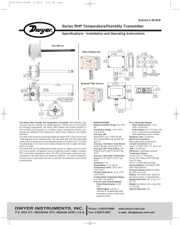
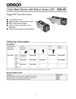
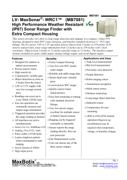
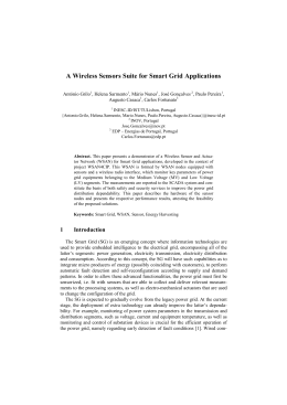
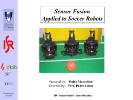
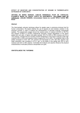
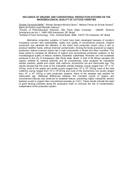
TELEDYNE
ANALYTICAL INSTRUMENTS
A
ccurate detection of trace levels of moisture has been a
challenge to the process world owing to the fact that high
concentrations of water are present in the atmosphere;
approximately 1% by volume in room air.
Teledyne Analytical Instruments is well aware of this challenge,
having successfully developed one of the broadest lines of trace
ppb/ppm O2 analyzers commercially available. In developing our
trace O2 line, we have had to contend with the fact that 209,000
ppm of O2 is present in the atmosphere – ready to jeopardize the
analysis of typically less than 1 ppm of O2. Teledyne is utilizing
50 years of expertise in detecting trace oxygen to produce a
complimentary line of trace moisture analyzers – Series 8800.
THE HEART OF THE PRODUCT – HYPER THIN
FILM (HTF) SENSING TECHNOLOGY
The 8800 series uses field proven aluminum oxide (Al2O3)
sensing technology to accurately detect trace moisture on either a
continuous or spot checking basis. All Al2O3 sensors share the same
basic operating principle: the capacitance measured between the
sensor’s aluminum core and gold film deposited on the oxide layer
varies with the water content.
The Series 8800 moisture sensor employs unique Hyper Thin Film
(HTF) technology, which offers three major structural improvements
in Al2O3 sensor design. These structural changes, noted below,
provide the user with increased sensitivity, greater stability, and
a quicker response time when compared to other conventional
aluminum oxide sensors on the market today.
BARRIER LAYER
In HTF sensors, the transition between the aluminum oxide and
the aluminum core is sharp and clearly defined. This inner barrier
layer produces a capacitor with its electrodes very close together,
which in turn leads to the sensor’s high wet to dry capacitance ratio.
The benefit of the high wet to dry capacitance ratio is that drift in
capacitance, due to undesirable factors, is much less significant.
This is clearly a benefit when comparing HTF versus conventional
sensors where temperature sensitivity and aging drift are concerned.
An added benefit associated with this sharp transition in the barrier
layer is a reduction in metal migration, one of the major causes of
aging drift in conventional sensors.
PORE GEOMETRY
The most significant difference between HTF and conventional sensors
is their pore geometry. While conventional sensors rely on hygroscopic
Al2O3 structures to attract water, HTF sensors instead rely on a pore
geometry that slows the Brownian motion of the water molecules
entering the pores.
The HTF sensor design results in more dielectric in the pores and
consequently a higher capacitance. An added benefit is derived
from the fact that HTF pore geometry does not significantly change
over time. Conventional Al2O3 structures, however, are not stable
and collapse slowly into non-hygroscopic structures. As a result,
conventional sensors are subject to higher drift rates and require
frequent re-calibration.
HYPER THIN FILM LAYER
The thinner oxide layer of the HTF sensor results in higher
capacitance changes (stronger signal generated than conventional
sensors) because capacitance is inversely proportional to the
distance of the capacitors’ plates from each other (the distance
between the aluminum core and the gold film deposited on the
oxide layer). The thinner layer also means water molecules will
travel faster in and out of the sensor pores, therefore responding
several times faster than conventional sensors.
NOTE: It is equally important to note
that HTF Al2O3 high capacitance
sensors are manufactured with high
uniformity allowing sensors to be freely
interchanged in the field without factory
re-calibration or changing of EPROMS,
as required with conventional Al2O3
sensors.
Pore geometry
Barrier layer
Layer thickness
Aluminum
Aluminum Oxide
Water Molecule
Gold
Drawing not to scale!
Graphic representation of
HTF vs. Other Al2O3 sensors
HTF™ vs. Conventional Al2O3 Sensor
Comparison of curve shape
HTF™ vs. Conventional Al2O3 Sensor
Change of Capacitance with Dewpoint
200
200
200
200
HTF™
XTR-100
Technology
150
Conventional
150
150
150
HTF™
100
nF
nF
Technology
100
100
100
50
50
HTF™ Technology
50
50
Conventional
Conventional Sensor
60x amplified
0
Dewpoint (°C)
30
10
-10
-30
-50
0
-70
30
10
-10
-30
-50
-70
-90
0
-90
0
Dewpoint (°C)
The change of capacitance with moisture of HTF sensors over the full measurement range is 60 times larger than that of conventional sensors. However, because of the improved linearity of HTF sensors at the low end, capacitance changes with moisture are about 600 times larger than that of conventional sensors. The larger sensitivity makes HTF sensors more stable and
resistive to other influences such as temperature, electrical noise, and long term drift.
VERSATILE DESIGN OPTIONS
The Series 8800 Single Point Trace Moisture Analyzers are provided in four compact, reliable designs with the ability to detect
moisture from -100°C to ambient dewpoint levels of +20°C on either a continuous or spot checking basis.
• 8800A – Flush Mount DIN enclosure with connections made
via a pluggable screw terminal block
• 8800B – Wall Mount N4X (IP65) enclosure with connections
made 3 bottom watertight fittings
• 8800P – Portable battery operated design available in the
Standard Version, I/O Version, and I/S Version (I/S version
suitable for hazardous areas)
• 8800T – Low-cost, loop powered 4-20mA transmitter design
with built-in LCD display
COMMON ELECTRONICS PLATFORM
The Series 8800 electronics feature a custom LCD 3.5 digit display with backlight capabilities (backlight not available on 8800T). Each controller
is operated through a menu-driven user interface. The push buttons or keys have a tactile feel, and to provide additional feedback to the user they
also produce a beep when depressed.
Each unit uses a state of the art microprocessor offering advanced intelligent features. In general, the MODE button navigates through the different user
options; the UP and DOWN buttons modify the units, values, or choices in the selected mode; and the Pressure Correct button is used to either abort out of a
mode or to activate the pressure correction function of the instrument.
The user can select the moisture analysis readout to be displayed as Deg C, Deg F, ppm and for natural gas applications in lbs of H2O/ million cft
or g/m3.
Most versions offer the common options of two adjustable alarms, an isolated 0-24mA or 4-20mA output or RS-232C serial interface The instrument
also has an indication for sensor open, short or electronic system failure to quickly alert the operator to a possible malfunction situation. In
addition, most versions offer extensive self-diagnostic features that are performed at both start-up as well as once every two minutes.
PRESSURE CORRECTION FUNCTION
The moisture readings are typically displayed at sensor pressure (atmospheric). Alternatively, the operator can display
the readings at the line pressure by selecting and setting the Pressure Correct Mode key. Readings are typically
read on a dewpoint basis in Deg C or Deg F. For readout on a ppm basis, the operator must control /
know the line pressure and program this value into the controller via the pressure correct function.
Teledyne’s XTR-100 sensor.
8800A
POSSIBLE FIELD MOUNTING CONFIGURATIONS
Control Room
FRONT VIEW
}
}
Outputs:
0/4-20mA or 0/1-5V
Alarms:
Form C, 2.5 A at 250 V AC
75Ω
Coaxial Cable
.81
8800A/B
RS-232-C
Power:
115V AC; 220 V AC, or
24 V DC, 24 V AC
Optional Intrinsic Safety Barrier
Inlet flow
control valve
5.1660
Field
Conduit
Moisture probe
Flow cell
PANEL THICKNESSES
UP TO 1.22 INCHES (31.0 MM)
MAY BE ACCOMMODATED.
Outlet flow
control valve
SCREW CLAMP
MOUNTING CLIP
(4 REQ/D.)
SIDE VIEW
Process pipe
Exhaust tube
SENSOR INSTALLATION CONSIDERATIONS
Proper sample handling is crucial to maintaining the tight moisture control demanded
by the industry today. Operators can assist in achieving a successful dew point
measurement by
MOUNTING PANEL
WEATHERPROOF GASKET
• Mounting the sensor as close to the measurement point as possible
• Mounting the instrument as close to the measurement point as
practical
Leakage, pressure / temperature gradients, and moisture absorption / desorption characteristics also need to be taken into careful consideration
when designing the appropriate sample system for dew point analysis. Material absorption / desorption affects overall system response. For
low dew point analysis applications, stainless steel wetted parts must be employed to reduce severe lag times typically associated with more
hygroscopic materials. Ideally a minimum number of joints / fittings and other plumbing upstream of the Al2O3 sensor should be maintained to
reduce the number of locations where moisture could collect or a leak could form.
Temperature Effect on XTR-100 Dewpoint Reading
Temperature Effect on Conventional and Ceramic AI203 Dewpoint Readings
20
10
Technology
0
0
-10
-10
-20
-20
Dewpoint°C
Dewpoint°C
10
20
HTF™
-30
-40
-50
-30
-40
MBW Reference Standard
-50
MBW Reference Standard
-60
HTF™ XTR-100 at 50°C
HTF™ XTR-100 at 20°C
-60
HTF™ XTR-100 at 50°C
-70
Ceramic at 50°C
-70
HTF™ XTR-100 at 20°C
-80
-90
-90
HTF™
Technology
Ceramic at 20°C
-80
-80
-70
-60
-50
-40
-30
-20
Reference Dewpoint°C
(MBW)
-10
0
10
20
-90
-90
HTF™
Technology
-80
-70
-60
-50
-40
-30
-20
-10
0
10
20
Reference Dewpoint°C
(MBW)
HTF aluminum oxide sensors offer excellent temperature stability over their full analysis range. Only below -70°C (dp) does
the measurement become slightly temperature sensitive. Temperature coefficients remain small enough, however, to allow
for software compensation. The temperature coefficients of conventional and ceramic sensors relative to their sensitivity to
moisture are too large to allow for an accurate compensation through software.
8800B
8800T
5.832
Viton A O-ring
MOUNTING HOLE
PATTERN
3/4"-16
14mm x 12.5mm
6.30
1.750"
LPDT
X10-3
SET %
HILO
PPM
TEMP
°C°F
DEWPOINT PSI G/M3 LGS
-1.8.8.8
2.230"
1.850"
flats for 17/8" wrench
0.600"
3.462
MOUNTING HOLE PATTERN
4.730
Operating Principle – Model 8800P
Aluminum oxide sensors absorb water molecules much faster
than desorb. It is therefore an advantage if, at the beginning of a
measurement, the sensor is dryer than the sample to be measured.
1/2" NPT HUB
(HIGH VOLTAGE
APPLICATION)
The 8800P accomplishes this by keeping the sensor in dry storage
until the measurement is taken. The sensor slides directly from dry
storage into the sample cell without coming in contact with ambient
air. After the measurement is complete, the sensor returns to
storage where it is dried down for the next sample.
3.558
(2) CABLE GRIP
(LOW VOLTAGE
APPLICATION)
1.563
.741
.745
CL
1.492
Sensor in
dry storage position
9
8
Dry Storage System –
Model 8800P
Sensor in
measuring position
9
5
2
2
1
1
6
6
3
4
6
5
4
6
11
3
11
7
10
10
7
1
2
3
4
5
6
Sample Gas IN
Sample Gas OUT
Piston
Sample Cell
Sensor
Spring loaded Teflon Seal
7
8
9
10
11
Sensor Actuator
Desiccant Chamber
Filter Mesh
Electronic Board
Instrument Case
This diagram (left) illustrates the mechanical design
of the 8800P dry storage sample cell system. The first
position depicts the sensor immersed in the desiccant
for dry storage. The sensor is separated from the
desiccant by a very fine, stainless steel mesh with a
thickness of approximately 5 mm. Close proximity of the
sensor to the desiccant is crucial for fast dry down.
With the sensor in the dry storage position, the sample
flows through the head space between the bottom of
the sample sell and the sensor piston. In order to take
a measurement, the gas outlet is temporarily blocked.
The pressure of the sample flow pushes the piston and
pulls the sensor into the sample cell where it wets up
quickly to the moisture content in the sample flow. An
accurate reading takes 1 to 2 minutes. Afterwards, the
sensor is pushed back into dry storage by means of the
sensor actuator which protrudes through the front of the
instrument.
8800 Series Specifications
8800A
Range by sensor type:
XTR-100
XTR-65
Readouts
Sensor type
Accuracy
Repeatability
Capacitance
Sensor temp range
Electronics temp
range
Response time
Pressure operating
range
8800B
8800T
8800P
-100 to 20°C (-148 to 68°F)
-65 to 20°C (-85 to 68°F)
Dew point in °F and °C, ppmv, gH2O / m3, lbs H2O / mmscf
High capacitance Al2O3 (HTF)
± 3°C (±5.5°F) or ±1% of the span
± 0.5°C (±0.9°F)
15 nF to 200 nF
-30 to 50°C (22 to 122°F)
-10 to 50°C (14 to 122°F)
For a step change from -40 to -60°C
Standard: 500 psi (34 Bar)
Optional: 5000 psi (340 Bar)
• 63% in 90 seconds • 90% in 450 seconds
Standard 28 psi
(2 bar)
Max: 100 psi
(6.9 Bar)
Mechanical connection 14 mm x 1.25 mm threads, and 3/4" - 16 threads; flow cell with 1/4" tube 1/4" VCO input /
of sensor
fitting (option)
output ports
Electrical connections Female BNC
Female BNC
Female BNC
9 pin "D" for analog
connector
connector
connector
and RS-232
Intrinsically safe option Class I & II, Div 1, Groups A through G and
CENELEC, EexII A,B,C, T6 (when used with
optional safety barriers
Display / indicator
Backlit LCD, 3.5 digits
3.5 digit LCD (no
Backlit LCD, 3.5 digits
backlight)
Controls
4 push buttons
3 push buttons
4 push buttons
Power requirements
100 - 240 VAC, 50 or 60 Hz
24 VDC
9V battery
Output options
0/4 - 20 mA, RS-232
4-20 mA
0/4 - 20 mA, RS-232
Sensor cable
Coaxial cable (75Ω with capacitance of 50 pF/M)
N/A - sensor built in
Maximum cable length = 3000 feet
TELEDYNE
ANALYTICAL INSTRUMENTS
A Teledyne Technologies Company
16830 Chestnut Street
City of Industry, California 91748, USA
TEL: 626-934-1500 or 888-789-8168
FAX: 626-934-1651 EMAIL: [email protected]
www.teledyne-ai.com
© 2006 Teledyne Analytical Instruments, A Teledyne Technologies Company.
All rights reserved. Printed in the USA.
09/06LD
Warranty
Instrument is warranted for 1 year against defects in material
or workmanship
NOTE: Specifications and features will vary with application. The above are established
and validated during design, but are not to be construed as test criteria for every product. All specifications and features are subject to change without notice.
Download