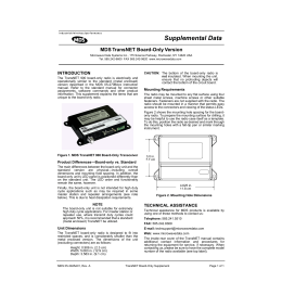
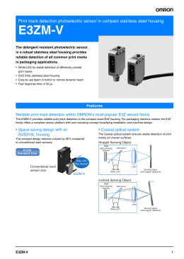
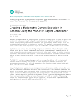
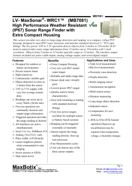
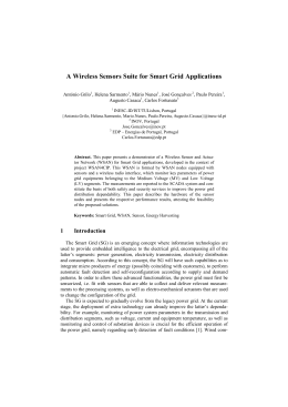
E3S-VS
E3S-VS
Color Mark Sensor with Red or Green LED
E3S-VS
Rugged IP67 Color Mark Sensor
■
■
■
■
1 ms response time
Detects a wide variety of color marks
PNP or NPN output models
Light-on/ Dark-on operation, wire
selectable
■ Vertical and horizontal mounting styles
Ordering Information
■ SENSORS
Sensing distance
Light source
Mounting style
12 mm
Green LED
Horizontal
Part number
E3S-VS1E4
(See Note 1.)
E3S-VS1E42
—
E3S-VS5E42G
E3S-VS5E42R
E3S-VS1B4
E3S-VS1B42
E3S-VS1B43
—
E3S-VS5B42R
E3S-VS1C4
E3S-VS1C42
—
—
—
NPN w/
pull-up
resistor
PNP
open
collector
NPN
open
collector
35 mm
Vertical
50 mm
Red LED
Vertical
Note: 1. For H12 connector version of E3S-VS1E4 with 0.5 m cable, order E3S-VS1E4-P1J 0.5M
■ REPLACEMENT PARTS
Description
Mounting bracket for horizontal models (supplied with each sensor)
Mounting bracket for vertical models (supplied with each sensor)
Sensitivity adjuster knob (supplied with each sensor)
2
Part number
E39-L2
E39-L6
E39-G1
E3S-VS
E3S-VS
Specifications
Part number
Method of detection
Supply voltage
Current consumption
Sensing distance
E3S-VS14
Diffuse reflective
12 to 24 VDC
40 mA max.
12 mm with 2 x 2 mm
(0.08 x 0.08 in) black mark
on white background
Light source
Pulse modulated green LED
Detectable object type
Operation mode
Sensitivity
Mutual interference protection
Control
DC
Type
outputt
solid
state
Max. load
Max. on-state
voltage drop
On
Off
Output shortcircuit
DC power supply
reverse polarity
Response time
Circuit
protection
Indicators
Materials
Prewired
NEMA
IEC 144
Operating
Storage
Ambient temperature
E3S-VS542R
35 mm with 2 x 2 mm
black mark on
white background
50 mm with 3 x 3 mm
(0.12 x 0.12 in) black mark
on white background
Pulse modulated infrared
LED
Color marks on colored background (see Color Combination Chart)
Light-ON/Dark-ON, wire selectable
Adjustable
Provided
NPN-SPST open collector with constant current source (E3S-VSE4)
NPN-SPST open collector (E3S-VSC4)
PNP-SPST open collector (E3S-VSB4)
NPN type: Load (relay, sink) logic: 80 mA
Voltage (source) logic: 1.5 to 3 mA
PNP type: Load (relay, source) logic: 100 mA
1 VDC
1 ms max.
1 ms max.
Provided
Provided
Light Incident (red LED), Output Stability (green LED)
Plastic
Diecast zinc
Plastic
Side mounting with two through holes; Bracket E39-L2 and hardware included
3-conductor cable, 2 m (6.56 ft) length
160 g (5.64 oz.)
1, 4, 4X, 12 13
IP67
-25° to 55°C (-13° to 131°F)
-40° to 70°C (-40° to 158°F)
Lens
Case
Cable sheath
Mounting
Connections
Weight
Enclosure ratings
E3S-VS3E42G
■ OUTPUT CIRCUIT DIAGRAMS
NPN output w/ pull-up resistor
1
PNP output
Red (Brown)
Load
(relay
sink)
Photoelectric
sensor switch
4
3
Light-ON
mode
Dark-ON
mode
+12 to
24 VDC
0V
1
Black
(Blue)
Dark-ON
mode
+12 to
24 VDC
0V
0V
+12 to
24 VDC
+V
2.2 Ω
White
(Black)
Voltage
logic
(source)
Red (Brown)
Light-ON
mode
Photoelectric
sensor switch
0V
0V
+12 to
24 VDC
White
(Black)
4
3
Black
(Blue)
Load
(relay)
(source)
0V
IEC colors are shown in parentheses.
Note: 1. When the Black wire from the through-beam emitter is connected to the Black wire of the separate type receiver, the LED
indicator on the emitter will indicate Light Incident on the receiver.
2. When the Black wire from the through-beam emitter is connected to the Blue or Brown wire of the emitter, the LED indicator on
the emitter indicates Power On.
3
E3S-VS
E3S-VS
Engineering Data
■ EXCESS GAIN RATIO
E3S-VS1E4(2), E3S-VS1B4(2)(3)
Excess gain ratio
Excess gain ratio
E3S-VS5E42R, E3S-VSB42R
Detecting distance [mm (inch)]
with 2 x 2 mm (0.08 x 0.08 in)
black mark on white background
Detecting distance [mm (inch)]
with 3 x 3 mm (0.12 x 0.12 in)
black mark on white background
■ OPERATING RANGE
E3S-VS1E4(2), E3S-VS1B4(2)(3)
Parallel offset distance Y (mm)
E3S-VS5E42R, E3S-VSB42R
Detecting distance [mm (inch)]
with 3 x 3 mm (0.12 x 0.12 in)
black mark on white background
Detecting distance [mm (inch)]
with 2 x 2 mm (0.08 x 0.08 in)
black mark on white background
4
E3S-VS
E3S-VS
Dimensions
Unit: mm (inch)
■ HORIZONTAL MOUNTING TYPES
E3S-VS1■
■4
Mounting holes
Lens
10 x 15
(0.39 x 0.59)
* Mounting bracket E39-L2 may be attached to surface A .
** Cable length: 2 m (6.56 ft)
*** Includes the spot position of E3S-VS1■
■ 4.
■ VERTICAL MOUNTING TYPES
E3S-VS1■
■ 42
Lens
10 x 15
(0.39 x 0.59)
* Mounting bracket E39-L6 may be attached to surface A .
** Cable length: 2 m (6.56 ft)
*** Includes the spot position of E3S-VS1■
■ 4.
Mounting holes
5
E3S-VS
E3S-VS
E3S-VS5■
■ 42R
Mounting holes
* Mounting bracket E39-L6 may be attached to surface A .
** Cable length: 2 m (6.56 ft)
*** Includes the spot position of E3S-VS1n4.
■ SENSITIVITY ADJUSTER KNOB E39-G1 (included)
Operation
■ SELECTING THE PROPER SENSOR FOR COLOR MARK DETECTION
The charts identify the combinations of color marks and color
backgrounds that can be detected. Refer to the illustration for
other test parameters used in preparing these sample values.
Legend: ❍: Sensor detects the mark stably.
X: Sensor will not detect the mark.
—: Not applicable.
Green light source (E3S-VS1n4n):
Background
color
Black
Silver
Red
Orange
Yellow
Green
Blue
Purple
White
Black
—
❍
❍
❍
❍
X
X
X
❍
= 35 mm, θ = 90°
Silver
❍
—
❍
❍
X
❍
❍
❍
X
Red
❍
❍
—
X
❍
❍
❍
X
❍
Color of mark to be detected
Orange
Yellow
Green
❍
❍
X
❍
X
❍
X
❍
❍
—
❍
❍
❍
—
❍
❍
❍
—
❍
❍
X
X
❍
X
❍
X
❍
6
Blue
X
❍
❍
❍
❍
X
—
X
❍
Purple
X
❍
X
X
❍
X
X
—
❍
White
❍
X
❍
❍
X
❍
❍
❍
—
E3S-VS
E3S-VS
Red light source (E3S-VS5n42R);
Background
color
Black
Silver
Red
Orange
Yellow
Green
Blue
Indigo-blue
Purple
White
Black
—
❍
❍
❍
❍
X
X
X
❍
❍
= 50 mm, θ =100° to 105°
Silver
❍
—
X
X
X
❍
❍
❍
X
X
Red
❍
X
—
X
X
❍
❍
❍
X
X
Orange
❍
X
X
—
X
❍
❍
❍
X
X
Color of mark to be detected
Yellow
Green
Blue
❍
X
X
X
❍
❍
X
❍
❍
X
❍
❍
—
❍
❍
❍
—
X
❍
X
—
❍
X
X
X
❍
❍
X
❍
❍
Indigo-blue
X
❍
❍
❍
❍
X
X
—
❍
❍
■ DETECTING MARKS ON FILM
Purple
❍
X
X
X
X
❍
❍
❍
—
❍
White
❍
X
X
X
X
❍
❍
❍
❍
—
Mat aluminum plate
To detect marks on a transparent sheet (such as film), an
object with a high reflection factor must be placed behind the
sheet as shown in the figure at right. A mat aluminum plate is
recommended.
Dispersion can cause variation in the
detecting position. To eliminate this
problem, the film should be in
contact with the plate.
■ I/O CONNECTOR PLUG
NPN output
PNP output
XS2F-D421-DC0-A
XS2F-D421-GC0-A
NPN or PNP output
Type
Conductor
DC
Brown
Black
Blue
—
XS2F-D421-DC0-A
XS2F-D421-G81-A
Connector Pin
1
4
3
2
Application
Power supply (+V)
Output
Power supply (0 V)
No connection
OMRON ELECTRONICS LLC
OMRON ON-LINE
OMRON CANADA, INC.
One East Commerce Drive
Schaumburg, IL 60173
Global - http://www.omron.com
USA - http://www.omron.com/oei
Canada - http://www.omron.com/oci
885 Milner Avenue
Scarborough, Ontario M1B 5V8
1-800-55-OMRON
Cat. No. CEDSAX4
11/01
Specifications subject to change without notice.
7
416-286-6465
Printed in the U.S.A.
Download