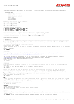
™
Operator’s Manual for BT-50EI
SPECIFICATIONS
Displacement:
Horsepower:
Ignition Style:
RPM:
Fuel:
Weight w/muffler:
2.84 cu in [46.5cc]
5.2 hp @ 9,000 rpm
Electronic Ignition System
1,100 – 9,000 rpm
Gas/2-cycle engine oil
4.8 lb [2.18kg]
Manufactured by FUJI-IMVAC INC.
YOKOHAMA, 235-0005 JAPAN
Worldwide Distributor (except Japan): Hobbico, Inc.
Champaign, IL 61826 USA
www.fuji-imvac.com
Fuji-Imvac is not related to the original Fuji Engines sold by Mecoa.
SAFETY TIPS AND WARNINGS
use a balanced spinner and a balanced prop. An unbalanced spinner
· Always
and prop combination will cause high levels of vibration and may cause the
propeller shaft to break.
use a lightweight spinner on your engine. Lightweight spinners are
· Always
considered to be those with a cone wall of 1mm or less. Heavy spinners could
cause the propeller shaft to break.
tighten the spinner and prop on the engine to prevent it from being
· Securely
thrown off the engine while running.
use a prop that has hit the ground. Even though it may look good from
· Never
the outside, it may be cracked on the inside which may cause it to disintegrate
while in use. Do not use a nicked, cracked or split propeller.
foreign objects away from the propeller. Make sure that nothing can be
· Keep
“sucked in” by the propeller. Never start the engine on loose gravel or sand.
away from the running engine, especially small children.
·· DoKeepnotonlookers
attempt to stop the engine by throwing anything into the path of the propeller.
sure the fuel line is well-secured to the engine and to the fuel tank so that
· Make
it won’t come off in flight.
not use silicone fuel line because it will be attacked by the fuel. Use vinyl or
· Do
neoprene rubber fuel line.
secure the fuel line away from the cylinder head. The engine’s heat can
· Always
damage the fuel line.
Never touch the engine after a run. The engine will be hot and it may burn you.
·· Before
transporting your model, remove all the fuel from the fuel tank and fuel lines.
Always
high-quality oil intended for 2-stroke engines.
·· Use onlyuselow-octane,
alcohol-free gasoline. The carburetor diaphragm will
gradually deteriorate if you use gasoline with alcohol (ethanol, gasohol, etc.).
··
·
·
·
··
·
·
You will need to replace the diaphragm in about 80 hours of operation if you use
gasoline with alcohol.
Muffler pressure to the fuel tank is not required.
Do not install your throttle servo or kill switch servo inside the engine compartment.
Doing so could cause radio interference. Install all electronic radio devices at least
305mm [12"] away from the engine. The throttle pushrod should be non-metallic.
In case the engine is not to be used for more than a month, drain the fuel tank
and remove any fuel from inside the carburetor. Do this by running the engine
at idle until it quits by running out of fuel. Keeping gasoline inside the carburetor
over an extended period of time will damage the diaphragm valve and clog
passages inside the carburetor.
Because the carburetor is more complicated than those used in glow engines,
keep the fuel clean by using a fuel filter. Use a filter intended to be used with
gasoline engines. Metal filters intended for glow engines are too coarse and will
not screen out finer particles. Always filter your fuel by using an appropriate filter
before putting it into the airplane’s fuel tank.
If you intend to run this engine on an engine stand, or on any other rigid mount,
use rubber mounts. The crankcase and other parts of the engine may crack if
you do not provide some kind of vibration absorption mechanism. A rubber
mount is not necessary if the engine is mounted on a model airplane.
Do not operate the engine in a closed room or where ventilation is not adequate.
Gasoline is extremely flammable. Keep it away from an open flame, excessive
heat or sources of sparks. Do not smoke near the engine or the fuel tank.
This engine was designed for use in a model aircraft. Do not attempt to use it
for any other purpose.
Always install a kill switch that can be operated both manually and with the R/C
transmitter.
PARTS LIST
BT-50EI Engine
Ignition Module
62.5mm EIS Propeller Flange with
Propeller Washer
8mm Propeller Bolt
Muffler
Muffler Gasket
(2) 6 x 65mm Muffler SHCS
(4) 5 x 22mm SHCS with Lock
Washers and Washers
280mm of Gas Tubing
Spark Plug Wrench
4mm Allen Wrench
2
FEATURES
Ignition Timing: The BT-50EIS features an electronic ignition system
· Automatic
that advances the ignition timing as the engine rpm increases. This ensures a
·
·
·
delayed ignition timing at low rpm for easy starts and good low-end engine
performance, and advanced timing at high rpm for good high-end power.
The ignition module is waterproof.
The ignition module runs on any 4.8V battery. The current consumption is
approximately 188mAh.
An optional Digital Tachometer (FJIG9920) is available to monitor rpm and
ignition battery voltage.
SPARK PLUG
The recommended spark plug is a Champion RCJ-6Y or 7Y. To avoid improper
operation or possible engine damage, do not use any other type of spark plugs.
The plug gap should be 0.4mm to 0.6mm [0.016" to 0.024"]. If the plug gap is
incorrect, adjust it with a spark plug gapping tool, wash it with gasoline and allow
it to dry completely before you reinstall the plug in the engine.
Note: If you want to check if the spark plug works, remove the spark plug from
the engine, connect it to the coil and make sure the metallic threaded end of the
spark plug touches the engine. Spin the propeller rapidly through top dead center
and check for a spark. This procedure only works in a dark room as there is too
much light outside to see the spark.
The various spark plug manufacturers have much information on their web sites
regarding spark plug performance and health. For more information, check:
http://www.championsparkplugs.com/sparkplug411.asp
PROPELLER
Always use a well-balanced, high-quality propeller.
The recommended propellers are:
High Performance Wood Prop:
18" X 8"
18" X 10"
20" X 10"
Carbon Prop:
20" x 12"
22" x 10"
22" x 12"
During our tests, our Fuji-Imvac BT-50EI turned a Bolly 20" x 12" carbon prop at
7600 rpm.The engine was new with 90 minutes of breaking in. The test conditions
were: Temperature 10°C [50°F], humidity 40%, elevation at sea level. Performance
may vary depending on atmospheric conditions.
3
OIL
Fuji-Imvac has developed a special oil to work with their engines. This oil is of extremely
high-quality and it has exceptional lubricating properties. This oil can be mixed with
gasoline at much higher ratios than other engine oils which allows the engine to
develop more horsepower and last longer. It is recommended that you use Fuji-Imvac
oil with all your Fuji-Imvac engines. Break-in procedures are slightly different than those
when using standard oils. Please refer to the table below for oil contents. Fuji-Imvac Oil
bottles of different sizes are available from your Fuji-Imvac distributor or hobby shop.
Break-in (Stage 1): 1 gallon of gasoline with 50:1 (2%) oil content.
Break-in (Stage 2): 1 gallon of gasoline with 100:1 (1%) oil content.
Normal running: In un-cowled or well-cooled installations 150:1 (0.65%) oil
content.
In-cowl or poorly cooled installations 100:1 (1%) oil content.
Do not try to use these engine oil ratios with any other brand of oil other than
the Fuji-Imvac oil.
Do not use the Fuji-Imvac oil with any other brand of engines.
If you have been running the engine on other oil and wish to switch to Fuji-Imvac
oil, follow the break-in procedure for Fuji-Imvac oil.
··
·
··
··
If Fuji-Imvac oil is not available, or if you prefer to use a different brand of oil, use
the standard fuel/oil ratios as shown below. Never experiment with cheap oil or
with obscure brand names. Be certain to select only high-quality oil that is
intended for use in gasoline R/C model airplane engines.
Break-in: 1 gallon of gasoline with 25:1 (4%) oil content.
Normal running: 40:1 (2.5%) oil content.
··
PREPARE THE ENGINE
1. Check to see that all screws and bolts are tight. Check carefully for any cracks,
broken or missing parts. Tighten or replace before proceeding.
2. Install the prop shaft on the flywheel using three 5 x
22mm SHCS with lock washers and washers. Use
threadlocking compound on the screws.
3. Install the spark plug in the cylinder head and
tighten.
4. Test fit the muffler and muffler gasket. Use two
6 x 65mm SHCS and washers to hold it in place.
4
5. Secure the ignition control
module ground wire to
the engine using one of
the 5 x 12mm SHCS.
6. Connect the ignition control module to the pick up sensor. The connector is
polarized and will only plug in one way.
7. Connect a kill switch to the ignition control module. It is recommended to install
a manual switch and a servo operated switch. This can be accomplished using
two receiver ON/OFF switches.
8. Connect the ignition module battery. Any 4.8V, 500mAh and above battery will
work well for this. The approximate current consumption of the ignition switch
module is 188mAh.
INSTALLING THE FUJI-IMVAC BT-50EI ON YOUR AIRPLANE
Note: The Fuji-Imvac BT-50EI must be installed on a 12mm [1/2"] lite ply firewall
or on a 9.5mm [3/8"] birch ply firewall. The firewall must be securely glued to the
airplane. Use triangle stock and pin the firewall with hardwood dowels to reinforce
the firewall glue joints. Never install the Fuji-Imvac BT-50EI onto a firewall thinner
than specified because it may fail due to the power of the engine.
Note: The length of the engine from the back on the engine mount to the propeller
washer is 166mm [6.5"] when using the stock (62.5mm [2.46"]) prop flange.
1. Use the supplied template (on the back cover of this manual) to drill the engine
mounting bolt holes and the necessary clearance hole on the firewall.
2. Install the engine on the firewall
using four 6.4 x 32mm or 1/4" x
1-1/4" socket head cap screws, four
6mm [1/4"] flat or lock washers and
four 6mm [1/4"] blind nuts. Use some
threadlocking compound, such as
Great Planes® Pro™ Threadlocker
(GPMR6060), on the screws.
5
3. Install the fuel tank in the airframe. Use only gasoline-safe fuel lines. One line
should go to the carburetor and the other is to be used as a vent. You can fill
the tank by using the carburetor line as fill line if you have access to it or install
a third line to be used as fill line.
4. Install a manual kill switch and a radio-operated kill switch. Install the kill switch
servo at least 305mm [12"] away from the engine.
5. Install the throttle servo at least 305mm [12"] away from the engine. Make sure
that you get the carburetor’s full range of rotation with your servo travel.
6. Install the ignition module securely in the airplane forward area. It is
recommended that a thin piece of foam rubber is placed between the module
and the mounting surface and that rubber bands are used to hold the module
in place. 4mm screws and washers can also be used to secure it in place, but
soft mounting the module is always the best choice.
7. Secure all connections with shrink tubing.
8. Cut all necessary clearance and cooling holes in the cowl.
9. Make sure the cowl is secured to the airplane and that the spinner to cowl
clearance is at least 3.2mm [1/8"].
BREAK IN THE ENGINE
break-in procedures for your engine will vary depending on the type of
· The
engine oil you will use. Please refer to the “Oil” section for fuel/oil mixture ratios
and break-in times.
Do
adjust the high-speed needle on the carburetor to break in the engine. If you
· do so,notcarbon
will accumulate in the spark plug and that will make ignition difficult.
Do
not
run
at
full
for extended periods of time while breaking in your engine.
·· Make sure that thepowerengine
has adequate cooling. While breaking in, the engine
may run at slightly higher temperatures.
you wish to do so, you can break in your Fuji-Imvac BT-50EI while flying your
· Ifairplane.
Just make sure you observe all recommendations above.
STARTING PROCEDURES
There are four recommended ways to start the Fuji-Imvac BT-50EI:
A. Manual Starting:
Note: Use a thick glove to protect your hand while hand starting the Fuji-Imvac
BT-50EI.
1. The propeller should be installed on the prop spacer so that it is comfortable for
you to flip it through compression. You also need to position it in a way that when
you flip the propeller, the magnets are 20° clockwise from the magnet pick up.
2. Have someone help you hold the airplane while you start the engine.
3. Make sure the ignition is OFF, close the choke on the carburetor and open the
throttle slightly from the idle position.
4. Rotate the propeller slowly about 10 to 20 times (more in winter) until fuel begins
to be drawn into the carburetor. Another way to prime the engine is to rotate the
prop clockwise from bottom dead center to top dead center (compression) and
then counterclockwise back to bottom dead center repeatedly.
6
5. Switch the ignition to ON.
6. Flip the propeller clockwise several times briskly.
7. After you hear some initial firing sounds, move the choke lever to the OPEN position.
8. Set the throttle to a high idle. Set the prop so that the magnets are 20° clockwise
from the magnet pick up when viewed from the front.
9. Flip the prop through compression rapidly. If this is done properly, the engine
will start between the first and the eighth flip of the prop. During our testing,
starting took an average of 3-4 flips.
10. After starting, let the engine idle for two to three minutes. Open and close the
throttle slowly until the engine runs smoothly at idle and at full throttle.
Acceleration should also be smooth.
11. If your engine does not start, repeat the procedure.
B. Electric Starter Use:
1. Make sure you use a good quality, lightweight aluminum spinner.
2. Have someone help you hold the airplane while you start it.
3. Make sure the ignition is OFF, close the choke plate on the carburetor and open
the throttle slightly from the idle position.
4. Use your electric starter to turn the engine over for several seconds.
5. Switch the ignition to ON and open the choke.
6. Set the throttle to High Idle and use your electric starter to turn over the engine
until it starts.
7. After starting, let the engine idle for two to three minutes. Open and close the
throttle slowly until the engine runs smoothly at idle and at full throttle.
Acceleration should also be smooth.
8. If your engine does not start, repeat the procedure.
C. Spring Starting:
1. Have someone help you hold the airplane while you start it.
2. With the ignition OFF, close the choke plate on the carburetor and open the
throttle slightly from the idle position.
3. Rotate the propeller slowly about 10 to 20 times (more in winter) until fuel begins
to be drawn into the carburetor. Another way to prime the engine is to rotate the
prop clockwise from bottom dead center to top dead center (compression) and
then counterclockwise back to bottom dead center repeatedly.
4. Turn the ignition switch to the ON position.
5. Hold the propeller, turn it 360° clockwise (one full turn) and let it go (move hand
quickly away from the propeller arc).
6. After you hear some initial firing sounds, move the choke to the OPEN position.
7. Repeat Step 5 until your engine starts.
D. Onboard Electric Starter Use:
Follow the instructions supplied with the onboard electric starter.
7
ENGINE ADJUSTMENTS
make high- and low-speed needle adjustments with the engine shut off.
· Always
Also make sure the ignition is OFF.
the needle marked “H” for high-speed rpm. Adjust the needle marked “L”
· Adjust
for low-speed rpm.
A. Normal high- and low-speed needle settings:
It is not necessary to change the needle settings if the engine runs smoothly.
Normally only the “H” needle will need adjustment from time to time and only by
a small amount.
H: Open the needle 3/4 of a turn from the closed position (±1/4 of a turn in winter).
L: Open the needle 1-3/8 turns from the closed position (±1/4 of a turn in winter).
Only adjust the high- and low-speed needle within the above range.
B. Idle adjustment:
Note: Do not confuse the idle screw with the low-speed needle “L”. The idle screw
physically adjusts how much the carburetor valve can close. The low-speed needle
“L” adjusts the gasoline to air mixture when the engine is running at low rpm. If your
engine appears to work correctly except that the low rpm are not as low as you
want them to be, then adjust the idle screw. If your engine behaves erratically at
low rpm, then adjust the low-speed needle “L”. When adjusting, turn the screw
about 1/8 of a turn each time. A dirty plug will make it difficult to adjust the idle rpm.
Follow the recommended procedures if any of the following happens:
Problem:
1. The engine hesitates when accelerated rapidly.
2. The rpm increases at idling.
3. The engine stops when the throttle is moved from high to low.
Solution:
Your low-speed needle “L” is too lean. Open it up about 1/8 turn and try again.
8
Problem:
The idle is not steady.
Solution:
Your low-speed needle “L” valve is too rich. Close it 1/8 turn and try again.
C. High-speed Adjustment:
The high-speed rpm and transition performance is adjusted with the high-speed
“H” needle valve. When adjusting, turn the screw about 1/8 of a turn each time.
The position of the “H” needle will vary according to air temperature and field
elevation. If your engine is running smoothly, then do not adjust this needle valve.
Follow the recommended procedures if any of the following happens:
Problem:
1. Engine stops at full throttle.
2. Engine hesitates when accelerated rapidly.
3. The engine will not come up to full rpm at full throttle.
Solution:
Your high-speed needle “H” is too lean. Open it up 1/8 turn and try again.
Problem:
1. Your engine does not reach full rpm.
2. Carbon build-ups appear consistently on your spark plug.
Solution:
Your high-speed needle “H” is too rich. Close it up 1/8 turn and try again.
3-Year Limited Warranty For USA and Canada
Fuji-Imvac warrants this product to be free from defects in materials and workmanship for a period of three (3) years
from the date of purchase. During that period, Fuji-Imvac will, at its option, repair or replace without service charge
any product deemed defective due to those causes. You will be required to provide proof of purchase date (receipt
or invoice).
• This warranty does not cover damage caused by crash, abuse, misuse, alteration or accident. Damage caused by
customer disassembly, tampering, use of substandard fuel, use of incorrect accessories (spark plug, prop, etc.) or
any use of the engine for which it is not specifically intended will automatically void the warranty of the engine. If
there is damage resulting from these causes within the stated warranty period, Fuji-Imvac will, at its option, repair
or replace it for a service charge not greater than 50% of the current retail list price. Be sure to include your daytime
telephone number and e-mail address in case we need to contact you about your repair.
• Under no circumstances will the purchaser be entitled to consequential or incidental damages. This warranty gives
you specific legal rights and you may also have other rights, which vary from state to state.
• If you attempt to disassemble or repair this unit yourself, it may void the warranty.
For service on your Fuji-Imvac engine, either in or out of warranty, send it postpaid and insured to:
Hobby Services
3002 N. Apollo Dr. Suite 1
Champaign IL 61822 USA
(217) 398-0007
www.hobbyservices.com
Along with your engine and proof of purchase date, please include a complete written explanation detailing the
problem(s). State your name and address clearly. For repairs not covered under warranty, you must specify whether
you wish the charges to be billed COD or if you wish to be notified of the charges so you can send a check.
Outside USA and Canada, contact local importer for warranty information.
9
REPLACEMENT PARTS
To order replacement parts for the Fuji-Imvac BT-50EI, use the order numbers in
the Replacement Parts Lists that follow. Replacement parts are available only
as listed. Replacement parts are not available from Product Support, but can be
purchased from hobby shops or mail order/Internet order firms. If you need
assistance locating a dealer to purchase parts, visit www.greatplanes.com and
click on “Where to Buy.”
CARBURETOR PARTS LIST
Key #
Part No.
Description
FJIG3275 ............................... Carburetor
A ..........FJIG5460 ............................. Inlet Screen
B ..........FJIG6990 ............. Pump Body Complete
C ..........FJIG7290 ................................ Set Screw
D ..........FJIG7110 ...........................Pump Gasket
E ..........FJIG7050 .................... Pump Diaphragm
F ..........FJIG5285 .................... Idle Adjust Spring
G ..........FJIG5220 .....................Idle Adjust Screw
H ..........FJIG6240 ........................... Needle Valve
J...........FJIG6465 .................. Diaphragm Gasket
Key # Part No.
Description
K ..........FJIG5790 .... Metering Diaphragm Comp.
L ..........FJIG7630 ............................ Valve Spring
M..........FJIG5130 ............... Hinge Pin Set Screw
N ..........FJIG5100 .................................Hinge Pin
P ..........FJIG3750 ........................... Control Lever
Q ..........FJIG4590 .................... Diaphragm Cover
R ..........FJIG3000 ........................... Adjust Spring
S ..........FJIG5670 ....................Low Adjust Screw
T ..........FJIG7200 ................................ Set Screw
U ..........FJIG5010 ................... High Adjust Screw
10
ENGINE PARTS LIST
Key # Part No.
Description
8...........FJIG7470 ................. Spark Plug RCJ-6Y
10.........FJIG8610 ..... Spark Plug Washer 0.5mm
11.........FJIG4415 .............................Cylinder Set
12.........FJIG8290 .......................Hex Bolt 5x18/S
14.........FJIG4320 .......................Cylinder Gasket
15.........FJIG6630 .............................. Piston Ring
16.........FJIG6395 ................................ Piston Set
17.........FJIG6470 ................................ Piston Pin
18.........FJIG6540 ..................... Piston Pin C-Clip
20.........FJIG6570 ......................Piston Pin Collar
21.........FJIG4050 ...............Crankshaft Complete
22.........FJIG6180 ........Needle Bearing 2x8.8mm
23.........FJIG5400 ...............Inlet Manifold Gasket
24.........FJIG3150 ................... Carburetor Gasket
25.........FJIG3211 ............................ Insulator Set
26.........FJIG3870 ...............Crankcase Assembly
27.........FJIG3960 ...................Crankcase Gasket
28.........FJIG6270 ....................................Oil Seal
29.........FJIG3090 ....................Ball Bearing 6202
30.........FJIG4260 .... Crankshaft Washer 15.2x22
31.........FJIG7690 ............ Wooddruff Key 3x13x5
32A ......FJIG4110 ........Crankshaft Shim 0.05mm
32B ......FJIG4140 ........Crankshaft Shim 0.10mm
32C ......FJIG4170 ........Crankshaft Shim 0.15mm
32D ......FJIG4200 ........Crankshaft Shim 0.20mm
32E ......FJIG4230 ........Crankshaft Shim 0.30mm
33.........FJIG6900 .............................Pulse Fitting
35.........FJIG8320 .......................Hex Bolt 5x25/S
40.........FJIG8340 .......................... Hex Bolt 5x50
41.........FJIG8605 ................... Split Washer 5mm
42.........FJIG8645 .................... Flat Washer 5mm
45.........FJIG3275 ............................... Carburetor
47.........FJIG8255 .....Hex Button Screw 5x12mm
51.........FJIG1004 ........................................Rotor
52.........FJIG8770 .................... Flat Washer 7mm
54.........FJIG4740 ................ Flywheel Nut 12mm
55.........FJIG1003 ...............................Pulsar Unit
60.........FJIG8270 ......................Hex Bolt 5x15/W
82.........FJIG4800 ............ Fuel Pipe 3x5x110mm
84.........FJIG3390 .............................. Clip 5.5mm
87.........FJIG8652 ................... Split Washer 7mm
88.........FJIG4660 .......................... Engine Mount
89.........FJIG7171 ................ Hex Screw 5x15mm
11
MUFFLER AND ACCESSORIES PARTS LIST
Key # Part No.
Description
001..... FJIG1001 .......................Control Unit
002..... FJIG8360 .................... Propeller Bolt
003..... FJIG8395 ............ Hex Bolt 5x22/WS
005..... FJIG3690 ..... Box Wrench 10x19mm
019..... FJIG4918 ............. Hex Wrench 3mm
020..... FJIG4920 ............. Hex Wrench 4mm
030..... FJIG6035 ........................ Muffler Set
031..... FJIG5910 .................. Muffler Gasket
032..... FJIG8765 ............. Flat Washer 6mm
033..... FJIG8400 ......... Cap Screw 6x65mm
035..... FJIG4830 ......Fuel Pipe 3x5x280mm
OPTIONAL ACCESSORIES
FJIG1050 ...... Spring Starter
FJIG1186 ...... Onboard Electric Starter
FJIG4922 ...... Vibration Proofing Rubber (4 pieces/set)
FJIG8062 ...... Spinner Bolt Tru-Turn Adapter
FJIG9920 ...... Digital Tachometer
FJIG7683 ...... Prop Flange 62.5mm [2-7/16"] (included with engine)
FJIG7684 ...... Prop Flange 72.5mm [2-7/8"]
FJIG7685 ...... Prop Flange 52.5mm [2-1/16"]
12
ENGINE MEASUREMENTS
97mm
106mm
70mm
R24mm
70mm
84mm
120mm
184mm
86mm
63mm
42mm
166mm
13
OTHER ENGINES AVAILABLE FROM FUJI-IMVAC:
BT-64EI Engine
Displacement: 63.1cc (3.85 cu in)
Practical RPM Range: 1,100-9,000
FJIG0088
Output: 5.7 hp @ 9000 rpm
Weight w/Muffler: 5.3 lb (2.38kg)
Includes: Walbro® Carb, Champion RCJ6Y Resistor
Spark Plug, Muffler
Recommended Prop: Bolly 22 x 12 Carbon
With its innovative Electronic Ignition
System, Fuji-Imvac’s BT-64EI is lighter
than magneto-based gasoline engines which pays off in improved acceleration
and fuel economy. The compact size of
the EIS unit also simplifies engine
installation. And it’s very easy to use.
Just connect the unit’s universal battery
connector to any 4.8V battery pack (not
included) and give the prop a quick flip.
The EIS produces more spark, so less force is needed for engine starting. The
EIS controller box is completely sealed, protecting the internal components from
heat, vibration and moisture. Of course, with the BT-64EI you’ll also enjoy all the
traditional benefits of Fuji-Imvac power: a Walbro carb, direct linkage throttle
setup, insulating plate, regulating pump and Champion spark plug.
BT-86EI Twin Engine
FJIG0089
Displacement: 86.0cc (5.25 cu in)
Practical RPM Range: 1,100-8,500
Output: 7.5 hp @ 8,500 rpm
Weight w/Muffler: 7.5 lb (3.39kg)
Includes: Walbro® HDA186 Carb, Champion
RCJ6Y Resistor Spark Plug, Muffler
Recommended Prop: 24x12 Carbon @ 6400
rpm; 24x10 Carbon @ 7400 rpm
One of your biggest concerns
with large-scale aircraft is weight.
The BT-86EI Twin’s Electronic
Ignition System (EIS) is more
reliable than magneto systems
and significantly reduces overall
weight! That translates into better
acceleration AND fuel economy.
Plus, the EIS is easy to use: just
plug it in to a 4.8V battery (not
included) and give the prop a quick flip. Each cylinder of the BT-86EI Twin has a
compression relief valve. A one-way overflow valve removes excess fuel buildup.
The Walbro HCA186 carb features a spring-loaded control arm, plus a heat shield.
14
15
Entire Contents © Copyright 2009
FJIZ1187 for FJIG0087 V2
Baixar