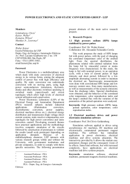
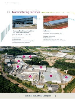
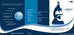
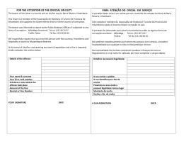
LM384 5W Audio Power Amplifier
General Description
Features
The LM384 is a power audio amplifier for consumer application. In order to hold system cost to a minimum, gain is
internally fixed at 34 dB. A unique input stage allows inputs
to be ground referenced. The output is automatically selfcentering to one half the supply voltage.
The output is short-circuit proof with internal thermal limiting. The package outline is standard dual-in-line. A copper
lead frame is used with the center three pins on either side
comprising a heat sink. This makes the device easy to use
in standard p-c layout.
Uses include simple phonograph amplifiers, intercoms, line
drivers, teaching machine outputs, alarms, ultrasonic drivers, TV sound systems, AM-FM radio, sound projector systems, etc. See AN-69 for circuit details.
Y
Y
Y
Y
Y
Y
Y
Y
Y
Wide supply voltage range
Low quiescent power drain
Voltage gain fixed at 50
High peak current capability
Input referenced to GND
High input impedance
Low distortion
Quiescent output voltage is at one half of the supply
voltage
Standard dual-in-line package
Schematic Diagram
TL/H/7843 – 3
C1995 National Semiconductor Corporation
TL/H/7843
RRD-B30M115/Printed in U. S. A.
LM384 5W Audio Power Amplifier
February 1995
Absolute Maximum Ratings
Storage Temperature
If Military/Aerospace specified devices are required,
please contact the National Semiconductor Sales
Office/Distributors for availability and specifications.
Supply Voltage
Peak Current
Power Dissipation (See Notes 3 and 4)
Input Voltage
b 65§ C to a 150§ C
Operating Temperature
0§ C to a 70§ C
Lead Temperature (Soldering, 10 sec.)
Thermal Resistance
iJC
iJA
28V
1.3A
1.67W
260§ C
30§ C/W
79§ C/W
g 0.5V
Electrical Characteristics (Note 1)
Symbol
Parameter
Conditions
Min
Typ
Max
150
Units
ZIN
Input Resistance
IBIAS
Bias Current
AV
Gain
POUT
Output Power
IQ
Quiescent Supply Current
8.5
VOUT Q
Quiescent Output Voltage
11
V
BW
Bandwidth
450
kHz
Va
Supply Voltage
ISC
Short Circuit Current (Note 5)
1.3
A
PSRRRTO
Power Supply Rejection Ratio
(Note 2)
31
dB
THD
Total Harmonic Distortion
Inputs Floating
THD e 10%, RL e 8X
40
50
5
5.5
POUT e 2W, RL e 8X
12
POUT e 4W, RL e 8X
nA
60
0.25
Note 2: Rejection ratio referred to the output with CBYPASS e 5 mF, freq e 120 Hz.
Note 3: The maximum junction temperature of the LM384 is 150§ C.
Note 4: The package is to be derated at 15§ C/W junction to heat sink pins.
Note 5: Output is fully protected against a shorted speaker condition at all voltages up to 22V.
Heat Sink Dimensions
Staver ‘‘V7’’ Heat Sink
Staver Company
41 Saxon Ave.
P.O. Drawer H
Bay Shore, N.Y.
Tel: (516) 666-8000
TL/H/7843 – 4
V/V
W
25
26
Note 1: V a e 22V and TA e 25§ C operating with a Staver V7 heat sink for 30 seconds.
2
kX
100
1.0
mA
V
%
Typical Performance Characteristics
Device Dissipation vs
Ambient Temperature
Thermal Resistance vs
Square Inches
Supply Decoupling vs
Frequency
Total Harmonic Distortion
vs Output Power
Output Voltage Gain vs
Frequency
Total Harmonic Distortion
vs Frequency
Power Supply Current vs
Supply Voltage
Device Dissipation vs
Output PowerÐ16X Load
Device Dissipation vs
Output PowerÐ8X Load
Device Dissipation vs
Output PowerÐ4X Load
TL/H/7843 – 5
3
Block and Connection Diagrams
Dual-In-Line Package
TL/H/7843 – 1
*Heatsink Pins
TL/H/7843 – 2
Top View
Order Number LM384N
See NS Package Number N14A
Typical Applications
Typical 5W Amplifier
TL/H/7843 – 6
Bridge Amplifier
TL/H/7843 – 7
4
Typical Applications (Continued)
Intercom
*For stability with
high current loads
TL/H/7843 – 8
Phase Shift Oscillator
TL/H/7843 – 9
5
LM384 5W Audio Power Amplifier
Physical Dimensions inches (millimeters)
Molded Dual-In-Line Package (N)
Order Number LM384N
NS Package Number N14A
LIFE SUPPORT POLICY
NATIONAL’S PRODUCTS ARE NOT AUTHORIZED FOR USE AS CRITICAL COMPONENTS IN LIFE SUPPORT
DEVICES OR SYSTEMS WITHOUT THE EXPRESS WRITTEN APPROVAL OF THE PRESIDENT OF NATIONAL
SEMICONDUCTOR CORPORATION. As used herein:
1. Life support devices or systems are devices or
systems which, (a) are intended for surgical implant
into the body, or (b) support or sustain life, and whose
failure to perform, when properly used in accordance
with instructions for use provided in the labeling, can
be reasonably expected to result in a significant injury
to the user.
National Semiconductor
Corporation
1111 West Bardin Road
Arlington, TX 76017
Tel: 1(800) 272-9959
Fax: 1(800) 737-7018
2. A critical component is any component of a life
support device or system whose failure to perform can
be reasonably expected to cause the failure of the life
support device or system, or to affect its safety or
effectiveness.
National Semiconductor
Europe
Fax: (a49) 0-180-530 85 86
Email: cnjwge @ tevm2.nsc.com
Deutsch Tel: (a49) 0-180-530 85 85
English Tel: (a49) 0-180-532 78 32
Fran3ais Tel: (a49) 0-180-532 93 58
Italiano Tel: (a49) 0-180-534 16 80
National Semiconductor
Hong Kong Ltd.
13th Floor, Straight Block,
Ocean Centre, 5 Canton Rd.
Tsimshatsui, Kowloon
Hong Kong
Tel: (852) 2737-1600
Fax: (852) 2736-9960
National Semiconductor
Japan Ltd.
Tel: 81-043-299-2309
Fax: 81-043-299-2408
National does not assume any responsibility for use of any circuitry described, no circuit patent licenses are implied and National reserves the right at any time without notice to change said circuitry and specifications.
This datasheet has been download from:
www.datasheetcatalog.com
Datasheets for electronics components.
Baixar