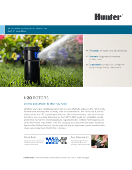
MAIN VALVE ACCESSORIES MAIN VALVE ACCESSORIES - 41 - MAIN VALVE OPTIONS MAIN VALVE OPTIONS BALANCED CONSTRUCTION There are installations where it is desirable to not have the inlet pressure forcing down on the Main Valve Disc. In these instances, the E Main Valve should be internally balanced. The balance parts allow the downstream pressure to rest on top of the disc, thus allowing for finer adjustments in the Main Valve travel and a smoother operating regulator. SECOWELD The greatest weakness in a High Pressure Valve is the threaded joint between the Seat Ring and the body. A slight leak developing at this point will gradually erode the Body metal, thus accentuating the leak and eventually ruining the body. Various impractical schemes, such as welding the Seat Ring into the Body, have been tried to overcome this weakness. The invention SECOWELD solves this problem and, at the same time, provides an easily renewable Seat Ring. In the SECOWELD Design, a SECO Metal Bushing is welded to and thus sealed in the Body and, in turn, is threaded to take the Main Seat Ring, which is also of SECO Metal. As SECO Metal resists wiredrawing, if slight leakage should occur, no damage can be done to the body or to the threads of either SECO Metal piece. EZ CONNECTIONS Provides the performance of a flanged connection with the simplicity of a union connection. Unlike conventional unions, EZ Connections do not require matched sets or springing pipe to clear cone tolerances and do not leak after just a few disassembly/reassembly cycles. Uniform end to end dimensions simplify rough-in schematics. Available on 1⁄2" through 2" threaded main valves in NPT, socketweld and threaded by socketweld connections. See Uniflex Couplings on page 374 CONDENSATION CHAMBER A Condensation Chamber is standard on the Type E5 Main Valve. A Condensation Chamber is standard on the Type E Main Valve when steam temperatures exceed 600°F. Any Main Valve discharging steam into a vacuum should include a Condensation Chamber. - 42 - LOW DIFFERENTIAL PRESSURE (LP) MAIN SPRING The E Series Main Valves provide superior regulation in a broad range of applications by utilizing a specialized Main Spring. When differential pressures between 10-50 psi are desired, E Main Valves should be equipped with the optional LP Main Spring. The LP Main Spring alone will achieve differential pressures to 15 psi. In order to attain differential pressures to 10 psi, optional 5B Open Elbow and 1⁄16" 4A Bleedport are required. COMPOSITION DISC In a Single Seat Main Valve, the Integral (all-metal) Disc is interchangeable with the Composition Disc Assembly. The Composition Disc is recommended for service on air, gas and water where absolutely tight shutoff is required and is available on Full and Normal seats and Parabolic valve plugs. The Composition Disc is suitable for pressures to 200 psi and temperatures to 200ºF. PARABOLIC DISC In order to meet special flow requirements, any Spence Main Valve can be equipped with a Parabolic or other specially shaped Disc. Due to the fact that the Spence Main Valve is operated by a large, balanced Diaphragm and is nearly frictionless in operation, special Discs are not required on normal installations. DASHPOT In order to prevent water hammer, Dashpots are required in all single seat, normally closed Main Valves used on liquid service, except Type C34. Dashpots are neither necessary nor desirable on steam, air or gas service and are not required in double seat valves or in normally open single seat valves. Illustration shows Dashpot and Composition Disc for initial pressures of 200 psig and less. For initial pressures greater than 200 psig, standard metal to metal seat and disc are used. - 43 - MAIN VALVE OPTIONS MAIN VALVE OPTIONS INSULCAP JACKET INSULCAP JACKET The Spence Insulcap Removable Insulating Jacket is an easy to install, reusable, one piece, asbestos-free insulating cover designed specifically to fit and be used on Spence Type E and Type C Main Valves. In addition to providing insulation to limit heat energy losses, using the Insulcap also helps reduce noise transmission. Being a removable and reusable jacket, the Insulcap makes replacement and maintenance costs much less than those associated with rigid insulation. Simple but effective Velcro® fasteners make the Insulcap easy to install. The Insulcap Jacket surface material is manufactured by a two step process, combining the benefits of impregnation and coating processes. It contains a well-stabilized woven glass reinforcement (result of impregnation) and an extremely durable surface membrane barrier (result of coating) wrapped around 1" thick mechanically bonded long textile glass fibers. The Insulcap Jacket is available for valve sizes 2" screwed and 2"6" flanged. Jackets for smaller or larger valves are available upon request. It is lightweight and will withstand temperatures to 550°F. INSULCAP JACKET OPTIONS ● Stainless Steel Mesh Lining for Temperatures above 550°F ● Lead Lining for extra noise reduction MATERIALS OF CONSTRUCTION Jacketing …………Chemical resistant silicone coated fiberglass Insulation ……Mechanically bound, 11# density fiberglass mat Thread & Seam Closure ……………………………………Kevlar DIMENSIONS inches (mm) AND WEIGHTS pounds (kg) VALVE SIZE 2 Screwed (50) 2 Flanged (50) 21/2 (65) 3 (80) 4 (100) 6 (150) DIMENSIONS IN INCHES WIDTH LENGTH 141/2 21 (368) (533) 171/2 261/2 (444) (623) 181/2 31 (470) (787) 191/2 35 (495) (889) 191/2 37 (495) (940) 221/2 43 (571) (1092) Heat Energy Savings Payback Period WEIGHT (lbs.) 2.6 (1.2) 2.7 (1.2) 4.6 (2.1) 4.65 (2.1) 6.15 (2.7) 8.55 (3.9) Regulator 50 psig 2" (50) 2.5" (65) 3" (80) 4" (100) 6" (150) - 44 - Millions of BTU’s Saved Annually 24.45 Payback in Days 157 27.51 182 30.57 168 36.68 165 51.96 171 TYPES A & B PANELS TYPES A & B PANELS ● Gauges indicate Air Loading, Air Supply and/or Delivery Pressures ● Integral ● 50 Filter Conditions Dirty Shop Air PSI Delivery Pressure ● Accurate Delivery Pressure over Wide Range of Flow OPTIONS ● HIGH DELIVERY PRESSURE MODELS ● MODEL A AIR ADJUSTMENT PANEL includes an air adjusting valve incorporating its own bleed and two gages; one for the supply air, the other to indicate the adjusting air. It comes complete and ready to be mounted directly on a control board or box. ● MODEL B AIR ADJUSTMENT PANEL is the same as the Model A with the exception that it has, in addition, a gage indicating the delivery pressure. TYPICAL CONFIGURATIONS For use with: TYPE B PANEL APPLICATION DATA ● To display Air Loading, Air Supply and/or Delivery Pressure ● To Remotely Adjust Air Pilots ● To Reduce Plant Air Pressure to Instrument Air Pressure for Signaling Regulators and Control Valves ● EA ● E8 ● Positioners ● EPC ● Any Controller Requiring Conditioned Pneumatic Signal ● To Filter Plant Air to Instrument Air Quality SPECIFICATION Air Adjustment Panel shall provide remote control for air actuated regulators and control valves. It shall convert plant air to instrument quality air and provide 0 to 50 psi delivery pressure The Panel shall have a flow capacity of 22 scfm. Panel shall have gauges indicating air load pressure and air supply pressure with option of process delivery pressure gauge. 71/4 (184) 1/4R (6.4) 1/4 NPT FOUR 7/32 (5.6) HOLES 1/4R (6.4) 111/4 (292) FILTER DRAIN 61/2 (165) 71/4 (184) TYPE A PANEL FILTER DRAIN 21/8 (54) 7 (178) FOUR 7/32 (5.6) HOLES TYPE B PANEL cutout 51/4 (133) high by 6 (152) wide - 45 - 21/8 (54) 7 (178) cutout 101/4 (286) high by 6 (152) wide AUXILIARY FITTINGS AUXILIARY FITTINGS BLEEDPORTS For steam, air and gas service, a 3/32" bleedport orifice is used for main valve sizes up to 8". For 10" and 12" main valve sizes, a 1/8" bleedport orifice is used. If the initial pressure or pressure drop is less than 15 psig, the orifice is reduced to 1/16". For liquids: fuel oil utilizes a 3/32" bleedport and all other fluids utilize a 1/16" bleedport regardless of pressure conditions. For main valve sizes up to 8" on long pressure drops, the orifice is sometimes increased to 1/8" to eliminate hunting or to make the valve close faster and open slower. 4A BLEEDPORT 1A UNION BLEEDPORT 8A BLEEDPORT TEE RESTRICTIONS Spare restriction fittings can be supplied blank and drilled for a particular main valve according to the table. If the initial pressure or pressure drop is less than 15 psi, an open fitting is used. All back pressure valves employ an open fitting. For liquid services (except back pressure) the restriction orifice is 1/16" for all sizes of main valves. 5A RESTRICTION ELBOW 7A SAFETY PILOT RESTRICTION TEE E MAIN VALVE RESTRICTION ORIFICES* MAIN VALVE SIZE 3/8 1/ 2 3/4 1 11/4 11/2 2 21/2 3 4 5 6 8 10 12 ORIFICE DRILL SIZE 60 60 60 60 58 58 56 56 53 51 47 45 42 17 7 * Steam, Air & Gas. If the initial pressure or pressure drop is less than 15 psi, a No. 5A elbow with orifice removed is used 7C ANTI-FREEZE RESTRICTION TEE OPEN FITTINGS 5B ELBOW 8B TEE 4B COUPLING 9B TUBING TEE 7B TEE - 46 - DECIMAL EQUIVALENT .0400 .0400 .0400 .0400 .0420 .0420 .0465 .0465 .0595 .0670 .0785 .0820 .0935 .1730 .2010 1B UNION
Download
