Dep. of Electrical and Computer Engineering,
Faculty of Science and Technology, University of Coimbra
João Rodrigues, Sérgio Brandão, Rui Rocha, Jorge Lobo, Jorge Dias
{joaor, brandao}@alumni.deec.uc.pt,
{jlobo, rprocha, jorge}@isr.uc.pt
Introduction
Omnidirectional Robot Model
Robot Construction and Assembly
The main goals of the RAC team (Robótica Académica de
Coimbra) are to have a competitive RoboCup soccer team,
interest students in robotics research, and build a team of high
performance robots suitable for educational and research
applications beyond the Robocup competition.
The first step to develop a robot controller was to derive the
inverse kinematics equations. In our model we consider several
parameters, including skew wheel angles. This parameter was
introduced to account for construction limitations that introduce
miss-alignments of wheels and influence the real robot trajectory.
The Robot’s construction went trough several stages. First, it was
built a prototype to test the hardware and to develop control
software. More four robots were constructed based on prototype
design.
In order to achieve these objectives, several tasks were assigned
to final project students. RACmotion was focused on robot
assembly and motion control.
v
w1
w1
v x
1
w 1 v w 1 M v
2 r 2
2 r y
w3
w3
v
3
cos( 1 )
sin( 1 )
cos( 1 ) R
M cos( 2 ) sin( 2 ) cos( 3 ) R
3
3
cos( ) sin( ) cos( ) R
3
3
3
3
3
RACmotion Objectives
• Omnidirectional drive control design and modeling;
• Project and implementation of a robot motion simulator
using MATLAB® and SIMULINK®;
• Development of a calibration procedure;
• Prototype development and assembly;
• Deployment and configuration of a robot’s embedded
Linux™ operating system;
• Development of a communication system and
communication protocol;
• Development of sensor and motor control software;
• Test and optimization of prototype mechanics and
software in real world conditions.
Fig.3 – Inverse kinematics equations.
Motion Simulator
Given the inverse kinematics equations, we simulated the
nonlinear system using SIMULINK®. Simulation is divided in
two parts: the motion controller and the motion simulator.
Control Software Development
Robot application software was developed for the Linux™
embedded operating system. The robot controller program has
two major tasks: communications handling and motion control.
Robot Hardware Main Features
Robot Operating System
Server
Omnidirectional drive and kicker;
NiMH batteries and PC104 power supply;
DC motors and encoders;
FPGA control card and motor driver daughter board;
PC104 embedded computer;
IEEE 802.11b wireless USB dongle;
Internet
Centralized
Controller
Socket TCP/IP
Stream Pipe
Wired local network
Client Application
Select
(Blocking)
Access Point
BSS = “RAC”
Controller (server)
Vision
Communication
Management
RACbot 5
Select
(25ms)
Movement
Control
Kicker
Control
RACbot 4
Message
Coding/Decoding
Sensors
Process 1
Process 2
Camera
RACbot 1
RACbot 3
Fig.4 – Simulator block diagram.
RACbot 2
Fig.9 - Robot controller diagram
Wireless 802.11b link
High performance Linux PC
FPGA Board
Kicker
Solenoid with
SuperCap
Bumpers
etc
4X Motor power drive
OmniDrive
3 DC motors
Battery pack + SuperCap + DC/DC
•
•
•
•
•
•
Fig.8- Several stages of robot construction and assembly.
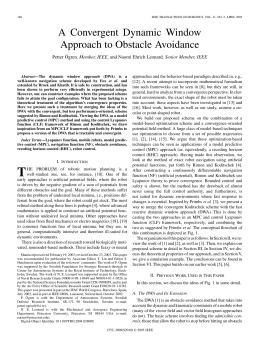
Tests and Results
Fig.5 – Robot trajectories can be visualized and the influence of motion
parameters can be studied.
The robot's hardware and software were tested in the playing
field. These tests helped us drawing conclusions about the design
options taken. Further tests will allow adjustments and upgrades
to the system.
Dribbler
DC motor
Fig.1 – Hardware architecture for RAC SSL robot.
Fig.6 – Robot's animation and motor's velocities during trajectory following.
Calibration
A calibration procedure was devised to estimate unknown wheel
skew angles. Given the non linearity of inverse kinematics
equations, we can't obtain a direct expression for α1, α2, and α3
(skew wheels angles). We developed an iterative calibration
method. When the robot movement is parallel to a wheel axis, i.e.
the wheel is not under traction, we assume that its effect on the
trajectory is minimal and can be neglected. Under this
assumption, we can decouple the behavior of two wheels from
the third one.
Fig.10 – Motion control tests in the playing field.
Conclusions
We presented the modelling, control and simulation of the
omnidirectional drive, and a calibration procedure. We presented
the kinematics equations, plus preliminary control simulation
results using a simple open loop controller. We also presented a
calibration method to estimate the wheel skew angles. These
robots will enable the setup of a competitive RoboCup team. The
aim of the design options taken during this project was to provide
a set of high performance robots suitable for educational and
research applications beyond the RoboCup game.
Fig.2 – Hardware components and preassembled robots.
Fig.7 – Skew wheels angles and their effect in robot trajectory.
Baixar