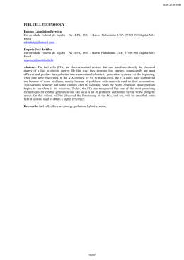
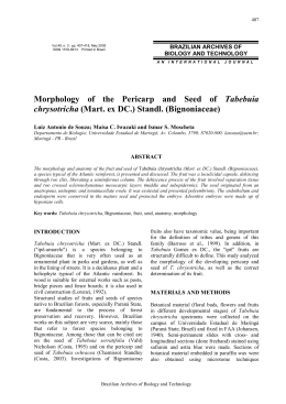
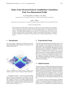
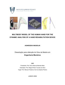
European Wind Energy Conference & Exhibition 2010
Tuesday 20 - Friday 23 April 2010, Warsaw, Poland
Poster - PO 328
PROCEDURES LABORATORY FOR SMALL WIND TURBINES TESTING
Jorge Antonio Villar Alé, Gabriel da Silva Simioni, João Gilberto Astrada Chagas Filho
Pontifical Catholic University of Rio Grande do Sul, Porto Alegre, Brazil
Faculty of Engineering - Wind Energy Center (CE-EÓLICA) – www.pucrs.br/ce-eolica
Av. Ipiranga, 6681– Prédio 30, Sala 120 - CEP: 90619-900; Tel: +55 51 3353-4438
ABSTRACT: Brazil presents favorable conditions for the use of wind energy, increasing even
more the current power production with renewable energy sources. Currently, the installed
capacity is approximately 700MW, even though it has a potential of about 150GW, and in order
to step further in the more dynamic way into the usage of this energy, it is necessary that the
country present specific politics for the scientific and technological development of wind energy
in Brazil, allowing technological resource exchange and creating mechanisms for professional
development. The present paper describes activities and the results obtained to testing small.
wind turbines in laboratory including methodology for evaluation of static bending test and cyclic
loads for small wind turbines using as references standards and procedures.
1. PERFORMANCE OF WIND TURBINES ON WIND TUNNEL
The international standard IEC 61400-12-1[1] has the methodologies for power curve
test of wind turbines (Fig. 1). The annex H of this standard has the procedures for small Wind
turbines, and the present paper uses this information as reference, however adapted to
measure the power curve on a wind tunnel. Other references [2, 3] present procedures and
results of small wind turbines.
Fig. 1 Standard for performance test of wind turbines
European Wind Energy Conference & Exhibition 2010
Tuesday 20 - Friday 23 April 2010, Warsaw, Poland
Poster - PO 328
2. METHODOLOGIES DEVELOPED IN LABORATORY
2.1 Small Wind Turbine Power Performance
The wind tunnel procedure presented in this paper doesn't have the intent of replacing
the field tests to measure the power curve of wind turbines, as specified in the IEC 61400-12-1.
It's a complement method that can be used as an aid to help preliminary tests in machines still
under development and verify its performance. The system is formed by the wind turbine,
battery bank, resistive load bank, load controller and a wind tunnel with open flow. The wind
speed is measured with a cup anemometer located between the aero generator and the end of
the wind tunnel (Fig. 2). A preliminary procedure is necessary to obtain the relation of the speed
read by the anemometer and the speed at the turbine plane. Later, this relation is used to
correct the power curve.
Fig. 2 Wind turbine testing procedure in wind tunel
The system assembled at the laboratory (Fig.3) uses a battery bank with capacity for
300Ah, an RMS power transductor of 5kW with accuracy of 0.2% of reading, wind tunnel
controlled by a frequency inverter of 74kW, resistive load bank with maximum power of 3kW,
calibrated anemometer and other meteorological sensors. The load controller was set to the
diversion control mode, in which a resistive bank is used to redirect the excess power instead of
letting it go to the battery. The operation range of this controller was set to 10% of the test
voltage.
Fig. 3 Data acquisition structure to wind tunnel test
European Wind Energy Conference & Exhibition 2010
Tuesday 20 - Friday 23 April 2010, Warsaw, Poland
Poster - PO 328
The variations of wind speed on the wind tunnel is automated, allowing to test the
turbines in a reduced time, the procedure of measuring the power curve lasts less than three
hours. To achieve that, a micro controlled system is connected to the frequency inverter that
turns the wind tunnel's fan on and controls the increase and decrease of the wind speed at the
turbine automatically.
2.2 Small Vertical Axis Wind Turbine Performance.
Besides the power test generators with small horizontal axis wind turbines whose
methodology has been presented in previous [3]. Currently are developments an methodology
for the mechanical torque rotor vertical axis wind turbines with the primary purpose of raising
the coefficient of power and torque coefficient of this rotors.
In the test, the permanent magnet generator is used as an electromagnetic brake in
order to produce a torque on the rotor axis wind. This allows a current control in the permanent
magnet generator which in turn will control the torque to be applied in the wind rotor. This
control is carried out a preliminary test for the maximum torque of the rotor to determine the
maximum brake rotor. These parameters are needed for the control of the braking doing a more
thorough analysis covering the full range of rotation and torque of the rotor.
This procedure uses beyond the majority of sensors already specified for the power
curve, and also, a torque wrench to measure the dynamic torque of the rotor wind. With the
torque characteristic curve obtained is possible to determine the coefficient of mechanical rotor
power (Cp), as essential to determine the best generator to be mounted on the rotor for the
construction of a wind turbine with a satisfactory return. In previous tests, tests were made with
various geometries [3], obtained with a wind tunnel under the current these limitations are the
range of speeds and test section. The results found previously are important since they show
the first results of performance rotors wind with new geometry tested in the laboratory.
For new tests with the rotors in the laboratory was needed to build a new structure to
support the wind turbine, including a mechanical system with the generator, a torque wrench,
flexible couplings and optical sensor for measuring revolutions per minute. A typical testing of
prototypes is shown in Fig. 4.
Fig. 4 Vertical axis wind turbine testing in wind tunnel
European Wind Energy Conference & Exhibition 2010
Tuesday 20 - Friday 23 April 2010, Warsaw, Poland
Poster - PO 328
2.3 Results of Small Horizontal and Vertical Axis Wind Turbines
Fig. 5 show the power curves obtained in laboratory for one small turbine made in
Brazil. The graphic show the data read by the datalogger as well as the power curve using the
bin method. Fig. 6 shows result of the torque to small vertical wind rotor. The torque is important
because it allows evaluate the aerodynamic performance of rotor wind for optimal integration
with the electric generator. The preliminary results Fig. 5 and Fig. 6 were obtained through small
rotor of high solidity from 1.0 m height and 1.0m diameter. In tests it was observed that the
machine has smooth running and low noise proved to be suitable for urban applications. These
tests will be repeated with the wind tunnel current.
Fig. 5 Power performance small wind turbine
10
9
Torque (Nm)
8
7
6
5
4
3
2
1
0
50
70
90
110 130 150 170 190 210 230 250 270 290 310 330
Rotation (rpm)
Fig. 6 Torque performance of small vertical axis wind rotor
European Wind Energy Conference & Exhibition 2010
Tuesday 20 - Friday 23 April 2010, Warsaw, Poland
Poster - PO 328
3. PROCEDURES FOR CYCLICAL TEST WIND TURBINE BLADES
A wind turbine is subjected during lifetime to a large number of dynamic loads produced
by the rotation of the blades as well as the turbulent nature of wind on the blades. Fig.7 shows
schematically the coordinate system of the blades of a turbine and the load caused by the
forces of wind and a detail of a blade to analyze load test bench.
Fig. 7 Bending load representation in blade wind turbine
The main objective in cyclic tests is to evaluate the test bench efforts to determine the
fatigue life of blades. Fatigue is a phenomenon that causes a gradual reduction in operating
capacity of the material when subjected to repeated loading. In the case of the blades of wind
turbines it is a cyclic loading. The fatigue comes from the action of stresses that vary in less
time not exceeding the elastic limit of the material. These loadings cause cracks and rupture of
the material.
There are several methods used to study and predict the fatigue of materials, and the
so-called Wohler method has been used to study wind turbine blades. This method studies the
behavior of fatigue by S-N curves, which relates the history of elastic tension acting on the
structure with the number of cycles that the material support before failing. To quantify the
damage caused to the material by cyclic loading of different amplitudes and different average
values are used to accumulation rule called linear Palmgren-Miner. In agree with this rule the
damage suffered by that part under the action of each amplitude of the cyclical stress is directly
proportional to the number of cycles loads that actuation on the amplitude stress.
3.1 Developing Cyclic Load Bench Test
The present section describes the methodological aspects as the project is in run-up in
test bench for testing the fatigue and static testing to determine preliminary magnitude of forces.
They can be used to wind turbine blades with a length up to 2.7 m. In the near future is
expected to continue with new publications show results of the bench in development. The test
bench will have a load cell located in the connecting rod between the ruler and the blade to read
their charges at the point of force application. The main reference used is the work of
Epaarachchi [4]. The blade is instrumented along its length at locations pre-defined with strain
gauges with a view to measure the deformation. The test will apply a cyclic load on the blades
for a wide range of frequencies and displacement. Tensions received by the blades of wind
turbines are caused by aerodynamic forces and inertial forces. This work is expected to
reproduce the same effort by shifts through a point of application of forces in the bench test
show in Fig. 8. This device induces the structure of the blade bending loads only, however the
European Wind Energy Conference & Exhibition 2010
Tuesday 20 - Friday 23 April 2010, Warsaw, Poland
Poster - PO 328
actual functioning originates efforts both bending and axial stresses. The system requires an
input of data adjusting the offsets and frequencies in the device test. A data acquisition system
is used presenting two main parts: strain gauges placed along the blade in preselected
locations and data logger for collecting and processing data.
Fig. 8 Fatigue Bench test to small wind turbine blades
In the work of Epaarachchi [4] the load levels based on the most critical point of the blade
are predetermined and later used in the tests with the aid of the loads determined by means of
finite elements (FEA). This work will be assessed on the best methodology that can be adopted
to determine the fatigue test conditions.
3.2 Preliminary Results of Static Bending Test
This section presents the tests of the three-point bending machine to analyze the mechanical
behavior of the blades when subjected to mechanical stress. The test consists of applying a
load in the center of the sample of the blade (proof body) supported at two points according to
standard ASTM E 855-90 [5]. The applied load came from an initial and slowly increased until
failure of the proof body. The value of the applied load versus the displacement of the central
point was the response of the test. Was used at a speed of 0.02 mm/s for the application of the
load, and tested two specimens under identical conditions. The distance between supports was
142 mm and was given a preload of 150 N before doing the test. Fig.9 show an example of the
test result where you can observe the application of the preload, the region of elastic behavior,
the region of plastic behavior and the subsequent fracture. The average value for the force was
1500 N and the strength of the early fracture of 1650 N. The samples had a mean total
displacement of 11 mm.
Fig. 9 Behavior of blade material in the static test machine
European Wind Energy Conference & Exhibition 2010
Tuesday 20 - Friday 23 April 2010, Warsaw, Poland
Poster - PO 328
CONCLUSIONS
The paper shows the automation procedure to obtain small wind turbine power
performance in open-jet wind tunnel adapting the IEC 61400-12 [1], specific for field tests of
wind turbines. The second part of this article allowed us to evaluate the following scenario
about the fatigue tests: (a) The test bench designed and built is ready for the testing of fatigue in
the blades, including the installation of load sensors, strain and controllers; (b) The results of
preliminary tests of flexion allowed the determination of the forces of the beginning of the
rupture of the specimens and the displacements suffered by them; (c) These values will be used
as initial parameters for establishing the conditions of fatigue tests.
REFERENCES
1. IEC 61400-12-1, Wind Turbine Generator Systems Part 12-1: Power Measurements of
Electricity Producing Wind Turbines. (2005).
2. Alé, J. A. V. Adegas, F. D. Simioni, G. C. da S.; Small Wind Turbine Testing: Indoor
Methodologies In: EWEC 2004 European Wind Energy Conference & Exhibition.
3. Alé, J. V.; Boscato S.; Simioni, G. C. da S.; Performance Evaluation of the next Generation
of Small Vertical Axis Wind Turbine In: EWEC 2007 - European Wind Energy Conference &
Exhibition.
4. Epaarachchi, Jayantha A. and Clausen, Philip D. Accelerated Full Scale Fatigue Testing Of A
Small Composite Wind Turbine Blade Using A Mechanically Operated Test Rig. SIF2004
Structural Integrity and Fracture. http://eprint.uq.edu.au/archive/00000836
5. ASTM Standard E290-92- Standard Test Method for Semi-Guided Bend Test for Ductility of
Metallic Materials. American Society for Testing and Materials,1982.
Baixar