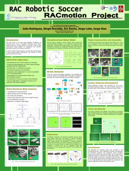
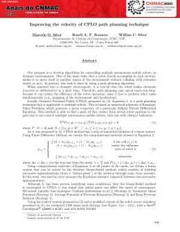
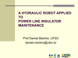
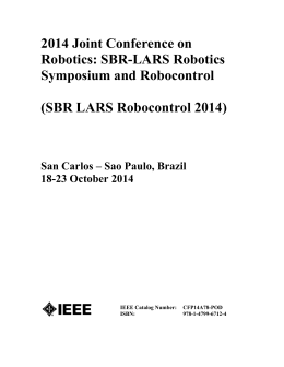
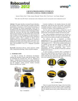
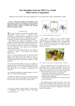
188
IEEE TRANSACTIONS ON ROBOTICS, VOL. 21, NO. 2, APRIL 2005
A Convergent Dynamic Window
Approach to Obstacle Avoidance
Petter Ögren, Member, IEEE, and Naomi Ehrich Leonard, Senior Member, IEEE
Abstract—The dynamic window approach (DWA) is a
well-known navigation scheme developed by Fox et al. and
extended by Brock and Khatib. It is safe by construction, and has
been shown to perform very efficiently in experimental setups.
However, one can construct examples where the proposed scheme
fails to attain the goal configuration. What has been lacking is a
theoretical treatment of the algorithm’s convergence properties.
Here we present such a treatment by merging the ideas of the
DWA with the convergent, but less performance-oriented, scheme
suggested by Rimon and Koditschek. Viewing the DWA as a model
predictive control (MPC) method and using the control Lyapunov
function (CLF) framework of Rimon and Koditschek, we draw
inspiration from an MPC/CLF framework put forth by Primbs to
propose a version of the DWA that is tractable and convergent.
Index Terms—Lyapunov function, mobile robots, model predictive control (MPC), navigation function (NF), obstacle avoidance,
receding horizon control (RHC), robot control.
I. INTRODUCTION
T
HE PROBLEM of robotic motion planning is a
well-studied one, see, for instance, [10]. One of the
early approaches is artificial potential fields, where the robot
is driven by the negative gradient of a sum of potentials from
different obstacles and the goal. Many of these methods suffer
from the problem of undesired local minima, i.e., positions different from the goal, where the robot could get stuck. The most
refined method along these lines is perhaps [4], where advanced
mathematics is applied to construct an artificial potential function without undesired local minima. Other approaches have
used ideas from fluid mechanics or electro magnetics [18], [19]
to construct functions free of local minima, but they are, in
general, computationally intensive and therefore ill-suited for
dynamic environments.
There is also a direction of research toward biologically motivated, nonmodel-based methods. These include fuzzy or neural
Manuscript received February 19, 2003; revised October 23, 2003. This paper
was recommended for publication by Associate Editor Y. Liu and Editor S.
Hutchinson upon evaluation of the reviewers’ comments. The work of P. Ögren
was supported by the Swedish Foundation for Strategic Research through its
Center for Autonomous Systems at the Royal Institute of Technology, Stockholm, Sweden. The work of N. E. Leonard was supported in part by the Office
of Naval Research under Grants N00014-98-1-0649 and N00014-01-1-0526, in
part by the National Science Foundation under Grant CCR-9980058, and in part
by the Air Force Office of Scientific Research under Grant F49620-01-1-0382.
This paper was presented in part at the IFAC World Congress, Barcelona, Spain,
July 2002, and in part at IEEE IROS, Lausanne, Switzerland, October 2002.
P. Ögren is with the Department of Autonomous Systems, Swedish
Defense Research Institute, SE-172 90 Stockholm, Sweden (e-mail:
[email protected]).
N. E. Leonard is with the Mechanical and Aerospace Engineering
Department, Princeton University, Princeton, NJ 08544 USA (e-mail:
[email protected]).
Digital Object Identifier 10.1109/TRO.2004.838008
approaches and the behavior-based paradigm described in, e.g.,
[12]. A recent attempt to incorporate mathematical formalism
into such frameworks can be seen in [8], but they are still, in
general, hard to analyze from a convergence perspective. In cluttered environments, the exact shape of the robot must be taken
into account; these aspects have been investigated in [13] and
[16]. Most work, however, as well as our study, assume a circular or point-shaped robot.
We build our proposed scheme on the combination of a
model-based optimization scheme and a convergence-oriented
potential field method. A large class of model-based techniques
use optimization to choose from a set of possible trajectories
[1], [2], [14], [15]. We argue that these optimization-based
techniques can be seen as applications of a model predictive
control (MPC) approach (or, equivalently, a receding horizon
control (RHC) approach). Having made this observation, we
look at the method of exact robot navigation using artificial
potential functions, put forth by Rimon and Koditschek [4].
After constructing a continuously differentiable navigation
function (NF) (artificial potential), Rimon and Koditschek use
Lyapunov theory to prove convergence. Bounded control and
safety is shown, but the method has the drawback of almost
never using the full control authority, and furthermore, is
not suited for dynamic environments where fast response to
changes is essential. Inspired by Primbs et al. [3], we present a
way to merge the convergent Koditschek scheme with the fast
reactive dynamic window approach (DWA). This is done by
casting the two approaches in an MPC and control Lyapunov
function (CLF) framework, respectively, and combining the
two as suggested by Primbs et al. The conceptual flowchart of
this combination is depicted in Fig. 1.
The organization of this paper is as follows. In Section II, we review the work of [1] and [2], as well as [3]. Then, we explain our
proposed scheme in detail in Section III. In Section IV, we discuss the theoretical properties of our approach, and in Section V,
we give a simulation example. The conclusions can be found in
Section VI. This paper builds on our earlier work [5], [6].
II. PREVIOUS WORK USED IN THIS PAPER
In this section, we discuss the ideas of Fig. 1 in some detail.
A. The DWA and Its Extension
The DWA [1] is an obstacle-avoidance method that takes into
account the dynamic and kinematic constraints of a mobile robot
(many of the vector field and vector field histogram approaches
do not). The basic scheme involves finding the admissible controls, those that allow the robot to stop before hitting an obstacle
1552–3098/$20.00 © 2005 IEEE
ÖGREN AND LEONARD: A CONVERGENT DYNAMIC WINDOW APPROACH TO OBSTACLE AVOIDANCE
189
TABLE I
COMPLEMENTARY PROPERTIES OF THE TWO APPROACHES
Fig. 1. Idea of the proposed approach can be seen as combining elements
from the original DWA with a construction guaranteeing convergence, proposed
by Rimon and Koditschek. This is done with inspiration from an MPC/CLF
framework suggested by Primbs et al..
while respecting the above constraints. Then an optimization is
performed over those admissible controls to find the one that
gives the highest utility in some prescribed sense. There are
different suggestions for the utility function in [1] and [2], including components of velocity alignment with preferred direction, large minimum clearances to obstacles, possibility to stop
at the goal point, and the norm of the resulting velocity vector
(large being good).
Brock et al. [2] extended the work in [1] by looking at holonomic robots (Fox et al. considered synchro-drive ones), and
more importantly, by adding information about connectivity to
the goal. The latter was done by replacing the goal-direction
term with the negative gradient of an NF, defined as the length
of the shortest (unobstructed) path to the goal [10]. Thus, they
were able to eliminate the local minima problems present in so
many obstacle-avoidance schemes (hence, the term “Global” in
the title of [2]).
The experimental results reported in [1] and [2] are excellent,
showing consistent safe performance at speeds up to 1.0 m/s with
a Nomadic Technologies XR4000 robot [2]. The results demonstrate an algorithmthat is safe by construction(inthe sense that the
robot never hits obstacles), and displays high efficiency in extensive experimental tests. But although Brock and Khatib argue that
the use of an NF makes the approach “Global,” it is never formally
shown. In fact, examples can be constructed where the robot enters a limit cycle, never reaching the goal, or actually consistently
moving away from the goal (see Section III-D).
B. Exact Robot Navigation Using Artificial Potential Fields
One of the main contributions of [4] is the clever construction of a special artificial potential. This potential has no local
minima except the global minimum at the goal. Furthermore, it
is continuously differentiable and attains its maximum value at
all the obstacle boundaries.
, where
is position,
Combining such a potential
with a kinetic energy term, one can construct a CLF as
The dynamics
and the control
,
is a dissipative force, yields
and stability in
where
the Lyapunov sense (see the Appendix for definitions of stability
and Lyapunov function).
is continuous on a
The controls are bounded, since
and
compact set. Further, the fact that
at the obstacle boundaries guarantees against collisions if the
initial velocity is small enough. The construction is, however,
only valid in a priori known “generalized sphere worlds” containing obstacles of specific categories. To adjust the scheme to
a specific robot requires a scaling of NF to make the maximal
smaller than the robot control bound. This, in turn, will
make the vast majority of prescribed control signals far below
the bound, resulting in very slow progress toward the goal.
We draw inspiration from the work in [4]; however, we relax
from continuous to piecewise-continthe constraints on
at the
uous and remove the requirement that
boundaries. By doing this, we hope to gain computational efficiency in calculating (and recalculating in case of new information) the NF, and also to allow quite general obstacle shapes.
Furthermore, removing these constraints gives the possibility of
(where is a scalar conadding the constraint
stant) used to enhance performance by allowing the consistent
use of control signals close to the given bound.
C. CLFs and MPC
In an interesting paper by Primbs et al. [3], the connection
between CLFs and MPC is investigated (MPC is also known
as RHC). They note the complementary properties shown in
Table I. In view of these properties, they suggest the following
framework to combine the complementary advantages of each
approach. The control law is chosen to satisfy a short-horizon
optimal control problem under constraints that ensure the existence of a CLF. The problem becomes one of finding a control
and a CLF
that satisfy (1)–(4) as follows
(1)
subject to
(2)
(3)
(4)
where
is a cost on states,
is a scalar,
is the
is a positive definite function, and
is
horizon length,
the trajectory when applying a pointwise minimum norm control scheme (for details, see [3]). This formulation inspires our
choice of a more formal, continuous-time formulation of the
DWA, allowing us to prove convergence.
190
IEEE TRANSACTIONS ON ROBOTICS, VOL. 21, NO. 2, APRIL 2005
III. A PROVEN CONVERGENT DWA
In the main parts of this paper, we will use the notation
for the state of the system. We adopt the
robot model from [2], which is basically a double integrator in the
,
with bounds on the control
,
plane
. Note that it was shown in [9] that
and on the velocity
an off-axis point on the unicycle robot model described by
Fig. 2. Graph discretization and computed shortest-path distances. Shaded
squares correspond to an obstacle.
can be feedback linearized to
.
For the environment, we assume that the robot’s sensors can
supply an occupancy grid map, i.e., a rectangular mesh with
each block being marked as either free or occupied, over the
immediate surroundings. Here, the size of the robot must be
taken into account, and additional safety margins, due to, e.g.,
localization errors, can be added. For example, if localization
errors are bounded, the obstacle regions can be expanded by the
corresponding amount, so that performance of the algorithm described below will still be guaranteed. A position marked as free
means that the robot does not intersect any obstacles when occupying that position. Thus, a map can be incrementally built as the
robot moves around. We assume, as did Brock and Khatib, that
the simultaneous localization and mapping (SLAM) problem
(see, e.g., [21]) is solved for us.
In cases where we are given a probabilistic occupancy grid,
a heuristic weighting in the utility function (10) is conceivable.
Other methods use a graph with weighted edge costs, reflecting
ease of traversal. Such ideas are, however, not applicable to this
scheme, due to the nature of the proof of Lemma 3.1.
A. Navigation Function
In our setting, the navigation function
, [2], [4], [10] approximately maps every free space position to the length of the
shortest collision-free path going from that position to the goal
point. Note that the details of our version are slightly different
from both [2] and [4], since the former is only piecewise-con. To be more precise,
stant, while the latter has to be at least
we make the following definition.
Definition 3.1 (NF): By an NF, we mean a continuous function defined on the connected part of the obstacle-free space
, containing the goal point and mapping to the real numbers.
An NF has only one local minimum, which is also the global
is
minimum. The set of local maxima is of measure zero.
piecewise-continuous, and the projection of the left and right
limits along the discontinuity edges satisfy
, where
is the direction of the edge and
is the gradient on each side of it.
Before investigating how to construct such a function in detail, we note that it is shown in [2] how to deal with the case
when the robot at first only knows its immediate surroundings
by use of its sensors. The idea is to assume free space at the unknown positions, and then recalculate the NF when sensor data
showing the opposite arrives. In this way, the robot guesses good
paths and updates them when new information arrives. The information is immediately taken into account in the optimization
[see (10)], thus avoiding collisions. The less urgent recalculation of the NF is then done. These updates are made at a time
scale much slower than the actual motion control, so in our considerations below, we assume the map to be static. Brock and
Khatib [2] used the gradient of the NF as the desired heading,
instead of using just the goal direction, as Fox did [1].
To compute the NF, we will use a technique similar to the one
suggested in [2]. There, however, the NF was piecewise-constant in the grids; here, we need a local-minima-free continuous function defined on all free space, making things somewhat
more complicated. The basic idea is to solve the shortest-path
problem in a graph discretization, and then make a careful continuous interpolation for the positions in between the discretization points. An example of the discretization can be seen in
Fig. 2. We note that while the grid is four-directional, the resulting robot velocities are not constrained to these directions;
indeed, the robot will often descend the gradient of the NF by
traversing the grids diagonally.
Lemma 3.1 (Construction of NF): An NF can be created by
the following procedure.
1) Make a graph out of the rectangular mesh of the obstacle
grid map, with vertices at the corners of each square and
edges along the square edges. Remove vertices and edges
that are in the interior of obstacles.
2) One of the vertices is chosen as goal point.
3) Solve the shortest-path problem in the graph (can be done
with polynomial time algorithms [11]). Mark each vertex
with the corresponding path length, and let this length be
the value of the NF at the vertex.
4) Divide the squares into triangles by drawing a diagonal
through the corner with the highest NF value (this is
shown to be unique later).
be a
5) In the interior of each resulting triangle, let
linear interpolation between NF at the three vertices, i.e.,
be a plane intersecting the three
let the value of
vertices.
ÖGREN AND LEONARD: A CONVERGENT DYNAMIC WINDOW APPROACH TO OBSTACLE AVOIDANCE
191
Fig. 3. Two possible cases, unique lowest NF(x) (left, as in the square
northwest of the goal point in Fig. 2) and two equal (right, as in the square
NF.
northeast of the obstacle in Fig. 2). The arrows indicate
0r
Proof: We begin by showing that there are no local
minima on the graph vertices and edges. Note that for a given
, if one path between and has even
pair of vertices
(odd) length (in multiples of the edge length ), so has any other
path. Therefore, two neighbors cannot have the same NF value.
on the edges is a linear interpolation between
Since
the value on the vertices, the edges have no local minima.
Furthermore, from every vertex, there is a shortest path to goal,
and along this path, NF decreases monotonically. Thus, there
can be no local minimum vertex, except the goal point.
Now we look at the values in the interior of the squares. Given
a square, look at the corner of lowest value, which may or may
not be unique. If it is unique and of value , then the two adjacent
corners must have value
, where is the side length, and the
, since no adjacent corners have
opposite corner must have
to ,
the same value (see Fig. 3, left). The diagonal is from
and in this case, the two triangles will actually form an inclined
plane, which obviously has no interior local minimum.
If the lowest value is not unique, the opposite corner must
have the same value and the two adjacent ones,
(see Fig. 3,
corners (unique as
right). The diagonal is between the two
stated in the construction), and this diagonal composes a ridge
of local maxima. There are, however, no local minima.
Thus, we have seen that there is only one local minimum, the
goal point. There might be local maxima on some diagonals, as
in Fig. 3 (right), but they are isolated lines, and thus, of measure zero. Finally, since NF is composed of triangles glued together, the projection along the edges fulfills
as above.
With an NF at our disposal, we are ready to look at the actual
choice of control.
Fig. 4.
Control sets C and C .
where
is the NF as explained above. Incorporating the
upper bounds on the control magnitude, we define the dissipative control set as follows.
):
Definition 3.2 (Dissipative Controls,
if
for some given
. We write
.
set is the shaded regions
A typical shape of the
in Fig. 4, where
(the nine dots) is a discretized (finite)
, since
subset of . Note that
, (the directional derivative along each axis
of the grid is equal to one, the gradient direction is diagonal
, see Fig. 3). Thus
to the grid, and the magnitude is
lies on a circle of radius . The outer circle of radius
bounds the control set.
Now the problem is to make sure the robot does not run into
obstacles. In the standard DWA, this is taken care of by choosing
among admissible, i.e., not colliding, controls in an optimization. Here we shall do the same.
A general formulation of the combined CLF/MPC scheme
now looks like this
(6)
subject to
B. General Control Scheme
collision free
The basic idea for the convergence proof is the same as in
[4]. First, we write the problem as a conservative system with
an artificial potential, and then we introduce a dissipative control
term. This dissipative control term is the sum of a turning force
(gyroscopic term) and a braking force (strictly dissipative term).
Chang and Marsden also identify a gyroscopic-plus-dissipative
control term for obstacle avoidance [20]. In the conservative
,
system, we choose the artificial potential to be
where is a positive constant that must be chosen smaller than
. Otherwise, the set
, defined later,
the control bound
will be empty, as seen in Fig. 4. The CLF is
(5)
(7)
(8)
(9)
where is the horizon length of the MPC. Here (7) gives stability in the Lyapunov sense. Safety is guaranteed by (8) and
(9), i.e., a planned collision-free trajectory ending with the robot
standing still. This corresponds to the policy of driving a car
slow enough so that you can always stop in the visible part of
the road. This is perhaps somewhat conservative on a highway,
but sensible on a small forest road where fallen trees might block
your way.
Note that the above formulation can, in principle, be applied
to enhance the performance of any approach with an artificial
potential having a well-behaved gradient, e.g., the original NF
suggested in [4] or a version of [18] and [19]. We believe that the
192
IEEE TRANSACTIONS ON ROBOTICS, VOL. 21, NO. 2, APRIL 2005
NF suggested above is a choice that yields high robot velocities
and good computational efficiency.
The optimal control problem of the MPC above can be computationally intensive, as seen in related approaches, such as [7].
Therefore, we devote the next section to showing how a very
coarse discretization can still yield quite good performance. In
Section IV, we give detailed proofs of the theoretical properties
of the proposed method.
C. Discretized Control Scheme
To end up with a computationally tractable version of the
MPC, we discretize the set of dissipative controls
into two
sets with piecewise-constant controls, relative to the velocity di, where is the time
rection. The horizon length is
over which the resulting control will be applied. After time , a
is discretized
new optimization is performed. The control set
and , corresponding to the two time interinto two sets,
and . A third set
is used when starting
vals of length
from a standstill, see Definition 3.3. To make the scheme precise, we formulate the following algorithm.
Algorithm 3.1 (Control Scheme): The control algorithm is
composed of the following steps, where step 3 is the main one.
, choose the control pair
, as given
1) If
in Definition 3.3, i.e., start out in a good direction.
, then set the new
. If fur2) Else, if
, then take the
thermore,
part
of the previous control pair and choose the
control pair
, i.e., reset and stop safely.
3) Else, choose the optimal solution to the MPC control
problem
subject to
is collision-free
(10)
4) Apply the first part of the chosen control pair for time
units, then repeat from 1.
Here,
is a user-defined decrease in over the time
. This timeout construction is needed to guarantee
against the hypothetical case of the robot velocity slowly
is not
approaching zero. Then the decrease bound
enough to yield convergence. The control sets are defined as
follows.
be the
Definition 3.3 (Control Sets, , , and ): Let
set of nine controls depicted as solid and shaded dots in Fig. 4,
be the set of four controls (a subset of ) in Fig. 4,
left, and
and
are defined relative to the velocity
right. Note that
be the control directed toward
direction . Furthermore, let
value (if
the corner of the current grid with the lowest
there are more than one such corner, the one closest to the robot
is chosen) and with control magnitude such that after applying
for time , and the middle, hardest braking control of
for time , the robot stops at the corner.
Intuitively, the scheme can be visualized as a downhill skier
on the slopes of the NF. Then the set of controls in
correspond to using all the acceleration provided by the slope
,
while possibly turning (gyroscopic forces). The set
on the other hand, corresponds to maximal braking maneuvers
Fig. 5. An obstacle, level curves of the NF, and parts of a trajectory, as well as
all the considered options.
(dissipative forces). The coarseness of the discretization, i.e., the
and , can be varied with respect to
cardinality of the sets
the amount of computational resources available.
As seen in Fig. 4, choosing close to the upper bound
makes the set
cover a very small area, while choosing small
limits the maximal forward acceleration available to the vehicle.
, since the acceleration is toward the corner
Note that
closest to goal. We further assume the grids to be small enough
control in
time units.
to be traversable by the
To make the current grid unique, positions on the boundary of
grids are assigned to belong to one of the adjacent grids.
is divided into two parts,
and
The interval
, where is the time step of the MPC control loop.
In the first part
, a control from , the set of controls in
, a control
Fig. 4, left, is chosen. In the second part
from , the set of controls in Fig. 4, right, is chosen. Note that
the controls in the sets above are constant with respect to the
consists of four controls
direction of the robot velocity, .
(the dots in Fig. 4, right) all reducing the speed of the robot.
consists of five controls on the border of the dissipative region
controls (the shaded dots). Thus,
(shaded area) and the four
the whole set
consists of
control
sequences.
In Fig. 5, we see parts of an executed trajectory together with
all the options evaluated in the optimization. An obstacle, as
well as the level curves of the NF, are also depicted.
It can be seen that in the first time step, the leftmost control of
is chosen, and in the second time step, the rightmost control
is the length of the time step, it is only the
is chosen. Since
part of
that is actually executed.
part is to guarantee safety. The time
The purpose of the
should be chosen long enough for the robot to stop
(since all the
controls are braking).
at (or before) time
The optimization is done with the constraint that the resulting
trajectory does not hit any obstacles, hence, the choice of the
rightmost control the second time. The fact that the previously
control is an option in
makes the last part of the
chosen
(safe) previously chosen control sequence an option in the next
ÖGREN AND LEONARD: A CONVERGENT DYNAMIC WINDOW APPROACH TO OBSTACLE AVOIDANCE
optimization. As a result, there is always at least one admissible (and therefore, safe) control sequence available. As stated
above, this is similar to always making sure you can stop in the
visible part of the road when driving a car.
One might argue that discretization and exhaustive search is
an inelegant solution. But we chose it for two reasons. The utility
varies rather slowly over the admissible
function
set of controls, and this set, in turn, can be very complex, e.g.,
unconnected if there are traversable paths to the right and to
the left, but the road straight ahead is blocked by an obstacle.
The constraints are also far from being a differentiable function
inequality. Due to these facts, a steepest-decent approach will
not do well.
D. Example of Convergence Failure of Previous Approach
193
is, however, not differentiable everywhere. Along the triangle
edges of NF, there are, in general, two different (left and right)
limits of the gradient. The projections along the edge is the
, making the inequality
same,
true. Furthermore, it is this projection that is needed when
determining according to the definition of ; see Definition
3.2 and Fig. 4.
If is not parallel to an edge, the problem with undefined
in the control will only occur in one isolated time inis not changed by whatever value we
stant, and thus,
use.
Theorem 4.1 (Finite Completion Time): Suppose the control
scheme in Algorithm 3.1 is used, and there is a traversable path
from start to goal in the occupancy grid. Then, the robot will
reach the goal position in a time bounded above by
The utility function of [2] that is to be maximized is
goal
where , , are the current position, desired velocity, and
acceleration, respectively. , , , and are scalar weights,
increases if the velocity is aligned with the NF graincreases with velocity (if far from goal), goal
dient,
is binary, 1 if the trajectory will pass through the goal point, and
is the decrease in NF value.
Consider a “T”-shaped, very narrow corridor, with the robot
initially in the top left end and the goal defined in the bottom
end. This will leave the robot accelerating maximally toward
the right. If the corridor is long and narrow enough, the speed
is going to be too great to allow a right turn at the intersection.
Thus, the robot will continue away from the goal. In particular,
when the corridor is very narrow and turning is not an option,
the robot must either brake or not. If the weights are such that
outweighs the
term, the robot
the velocity term
will just keep on going. Otherwise, it will brake maximally. If,
however, the acceleration is as powerful as the retardation, the
robot will oscillate back and forth in the upper part of the “T,”
and never be able to make the sharp turn into the goal part of it.
A similar counterexample was independently presented in [7].
Note that the Lyapunov property of (11) removes these kinds of
problems in the proposed approach.
IV. PROOF OF CONVERGENCE AND SAFETY
Before we formulate the main theorem of this paper we need
a lemma.
Lemma 4.1 (CLF): The function
is a CLF, and any
where
is the value of the CLF at the starting
position.
. Thus,
Proof: By Lemma 4.1, we have that
the system is stable in the sense of Lyapunov.
After a stop, the robot starts moving toward the corner
.
of the current grid closest to goal, i.e., with lowest
Then, the optimization improves on this, making the outcome at least as good as stopping at that corner (at a stop,
). Together with the fact that
, this means that the robot will never stop in that
grid again. Thus, the number of possible grids to occupy
(which is finite) is reduced by at least one between each
pair of stops. Since NF is the path length, the number of
. Therefore,
possible grids is bounded by
this is also a bound on the number of stops. The timeout
.
induces a stop if
-sized intervals without
This makes the number of
a stop bounded by
. Combining the two,
we get
.
Remark 4.1: Note that this is an extreme worst-case analysis.
In the simulations, the robot did not stop at all before reaching
the goal position.
Theorem 4.2 (Safety): Suppose the control scheme in Algorithm 3.1 is used, and the robot starts at rest in an unoccupied
position. Then, the robot will not run into an obstacle.
Proof: The proof relies on the recursive structure of
. The subset of noncolliding controls in
(that we are
optimizing over) is never empty, since we can always choose
(not yet applied) part of the previous
control
the
control.
sequence as our new
control satisfies the following inequality:
(11)
Proof: The candidate CLF is
, which is clearly positive definite with a global
. Differentiating with respect to
minimum at
time gives
, by the constraints on . The NF
V. SIMULATION EXAMPLE
To illustrate the approach, we chose a setting with three large
obstacles in a 9 9 m area, as seen in Fig. 6. We used parameters for the Nomadic Technologies XR4000 robot obtained from
m/s ,
m/s. We fur[2],
s,
s,
thermore set the parameters as follows:
194
IEEE TRANSACTIONS ON ROBOTICS, VOL. 21, NO. 2, APRIL 2005
Fig. 8. Robot velocity. Note how the speed is limited by v
how it decreases twice during the narrow passage.
Fig. 6. Obstacles and robot trajectory.
= 1:2 m/s and
This constraint is of the same sort as the dissipative constraint,
i.e., it can be depicted as another horizontal line above or below
the ones in Fig. 4. If the new constraint is more restrictive (lies
options will be placed just below
below the first two), the
it, instead of just below the others. Thus, in Fig. 8, the robot
m/s in the
reaches a “steady-state” velocity close to
open areas.
VI. CONCLUSIONS
In this paper, we have first presented the well-known DWA
to fast and safe obstacle avoidance in an unknown environment.
We then recast the approach in a continuous nonlinear control
framework suggested by [3]. With a few changes to the basic
scheme, we were able to prove convergence to the goal position.
This is significant, since the earlier scheme could be subject to
limit cycles, and even divergence.
APPENDIX
LYAPUNOV STABILITY THEORY
Fig. 7. Closeup of parts of the trajectory including all the evaluated options of
the MPC. The robot slows down in two places, (6.5,7.2) and (5.5,5.5), in order
not to collide.
. The resulting robot trajectory and the level curves
of the NF are also depicted in the figure. Note the absence of
local minima as guaranteed by the construction in Lemma 3.1.
In the beginning and the end of the trajectory, it can be seen how
the MPC minimization in (10) favors going perpendicular to the
level curves.
In Fig. 7, parts of the trajectory as well as the MPC options are
shown. The robot slows down in two places, as can be seen in
Fig. 8. These are located at (6.5,7.2) and (5.5,5.5), respectively.
controls make the
In the second instance, all the nonbraking
part of the
robot collide. The sharp-braking right turn, the
previous choice, is, however, safe and therefore applied. At the
first instance, (6.5,7.2), the nonbraking right turn is safe, but the
value (it is closer
braking left turn yields a lower
to the goal) and is thus chosen.
m/s bound, we impose the
To enforce the
additional acceleration constraint
Lyapunov theory is a very elegant and powerful tool used in
stability analysis of nonlinear systems. We follow Sastry [22]
closely, but for the sake of clarity and conciseness, we sacrifice
some generality, e.g., time dependence.
Throughout this section, we consider a system of nonlinear
differential equations
(12)
and
. A condition to guarwhere
antee existence and uniqueness of solutions is further needed,
e.g., locally satisfying the Lipschitz condition
where
is a fixed scalar. Points of interest in stability
analysis are the so-called stationary or equilibrium points.
Definition 6.1 (Equilibrium Point)
is said to be an equilibrium point of (12) if
We will now go on to investigate if a given equilibrium point
is stable or not.
ÖGREN AND LEONARD: A CONVERGENT DYNAMIC WINDOW APPROACH TO OBSTACLE AVOIDANCE
Definition 6.2 (Stable Equilibrium)
is said to be a stable point of
The equilibrium point
(12) if, for all
, there exists a
such that
where
is the solution of (12).
Definition 6.3 (Asymptotic Stability)
is said to be an asymptotically
The equilibrium point
stable point of (12) if
1) it is stable;
2) it is attractive, i.e., there exists a such that
where
is the solution of (12).
Note that 2) above does not necessarily imply 1). Before stating
the main stability result of Lyapunov theory, we need one more
definition.
Definition 6.4 (Locally Positive Definite Function)
A continuous function
positive definite function if, for some
is called a locally
and
and
where
is continuous, strictly increasing, and
.
Theorem 6.1 (Basic Lyapunov Theorem)
Suppose we are given a system (12), an equilibrium point
, and a locally positive definite function
.
1) If
(locally), then
is stable.
is locally positive definite, then
is asymptoti2) If
cally stable.
a Lyapunov funcIn both cases above, we call the function
tion.
For further results, we refer to the textbook used here [22].
REFERENCES
[1] D. Fox, W. Burgard, and S. Thrun, “The dynamic window approach to
collision avoidance,” IEEE Robot. Autom. Mag., vol. 4, pp. 23–33, Mar.
1997.
[2] O. Brock and O. Khatib, “High-speed navigation using the global dynamic window approach,” in Proc. IEEE Int. Conf. Robot. Autom., Detroit, MI, May 1999, pp. 341–346.
[3] J. A. Primbs, V. Nevistic, and J. C. Doyle, “Nonlinear optimal control:
A control Lyapunov function and receding horizon perspective,” Asian
J. Control, vol. 1, no. 1, pp. 14–24, Mar. 1999.
[4] E. Rimon and D. Koditschek, “Exact robot navigation using artificial potential functions,” IEEE Trans. Robot. Autom., vol. 8, no. 5, pp. 501–518,
Oct. 1992.
[5] P. Ögren and N. Leonard. “A provably convergent dynamic window approach to obstacle avoidance”. presented at 2002 IFAC World Congr..
[CD-ROM]
, “A tractable convergent dynamic window approach to obstacle
[6]
avoidance,” in Proc. IEEE/RSJ Int. Conf. Intell. Robot. Syst., Lausanne,
Switzerland, Oct. 2002, pp. 595–600.
[7] C. Stachniss and W. Burgard, “An integrated approach to goal-directed
obstacle avoidance under dynamic constraints for dynamic environments,” in Proc. IEEE/RSJ Int. Conf. Intell. Robot. Syst., Lausanne,
Switzerland, Oct. 2002, pp. 508–513.
195
[8] P. Althaus and H. Christensen, “Behavior coordination for navigation in
office environments,” in Proc. IEEE/RSJ Int. Conf. Intell. Robot. Syst.,
Lausanne, Switzerland, Oct. 2002, pp. 2298–2304.
[9] J. Lawton, B. Young, and R. Beard, “A decentralized approach to formation maneuvers,” IEEE Trans. Robot. Autom., vol. 19, no. 6, pp. 933–941,
Dec. 2003.
[10] J. Latombe, Robot Motion Planning. Boston, MA: Kluwer, 1991.
[11] E. W. Dijkstra, “A note on two problems in connexion with graphs,”
Numer. Math., vol. 1, pp. 269–271, 1959.
[12] R. C. Arkin, Behavior-Based Robotics. Cambridge, MA: MIT Press,
1998.
[13] K. O. Arras, J. Persson, R. Siegwart, and N. Tomatis, “Real-time obstacle avoidance for polygonal robots with a reduced dynamic window,”
in Proc. IEEE/RSJ Int. Conf. Intell. Robot. Syst., Lausanne, Switzerland,
Oct. 2002, pp. 3050–3055.
[14] N. Y. Ko and R. G. Simmons, “The lane-curvature method for local obstacle avoidance,” in Proc. IEEE/RSJ Int. Conf. Intell. Robot. Syst., vol.
3, Vancouver, BC, Canada, Oct. 1998, pp. 1615–1621.
[15] J. A. Benayas, J. L. Fernández, R. Sanz, and A. R. Diéguez. “The beamcurvature method: A new approach for improving local real-time obstacle avoidance”. presented at 2002 IFAC 15th Int. World Congr.. [CDROM]
[16] J. Minguez and L. Montano. “Robot navigation in very complex, dense
and cluttered indoor/outdoor environments”. presented at 2002 IFAC
15th Int. World Congr.. [CD-ROM]
[17] O. Khatib, J. Minguez, and L. Montano, “Reactive collision avoidance
for navigation with dynamic constraints,” in Proc. IEEE/RSJ Int. Conf.
Intell. Robot. Syst., Lausanne, Switzerland, Oct. 2002, pp. 588–594.
[18] P. Iniguez and J. Rosell, “A hierarchical and dynamic method to compute
harmonic functions for constrained motion planning,” in Proc. IEEE/RSJ
Int. Conf. Intell. Robot. Syst., vol. 3, Lausanne, Switzerland, Oct. 2002,
pp. 2335–2340.
[19] A. Elnagar and A. M. Hussein, “Motion planning using Maxwell’s equations,” in Proc. IEEE/RSJ Int. Conf. Intell. Robot. Syst., vol. 3, Lausanne,
Switzerland, Oct. 2002, pp. 2347–2352.
[20] D. E. Chang and J. E. Marsden. Gyroscopic forces and collision avoidance. presented at Conf. Honor of A. J. Krener’s 60th Birthday. [CDROM]
[21] P. Jensfelt and S. Kristensen, “Active global localization for a mobile
robot using multiple hypothesis tracking,” IEEE Trans. Robot. Autom.,
vol. 17, no. 5, pp. 748–760, Oct. 2001.
[22] S. Sastry, Nonlinear Systems: Analysis, Stability, and Control. New
York: Springer-Verlag, 1999.
Petter Ögren (M’04) was born in Stockholm,
Sweden, in 1974. He received the M.S. degree in
engineering physics and the Ph.D. degree in applied
mathematics from the Royal Institute of Technology
(KTH), Stockholm, Sweden, in 1998 and 2003,
respectively.
In 2001, he visited the Mechanical Engineering
Department, Princeton University, Pronceton, NJ, for
four months. He is currently working as a Researcher
with the Swedish Defence Research Agency (FOI),
Stockholm, Sweden. His research interests include
multirobot systems, formations, navigation, and obstacle avoidance.
Naomi Ehrich Leonard (S’90–M’95–SM’02) received the B.S.E. degree in mechanical engineering
from Princeton University, Princeton, NJ, in 1985,
and the M.S. and Ph.D. degrees in electrical engineering from the University of Maryland, College
Park, in 1991 and 1994, respectively.
She is a Professor of Mechanical and Aerospace
Engineering with Princeton University, and also an
Associated Faculty Member of the Program in Applied and Computational Mathematics at Princeton.
From 1985 to 1989, she worked as an Engineer in the
electric power industry for MPR Associates, Inc., Alexandria, VA. Her research
focuses on the dynamics and control of mechanical systems using nonlinear
and geometric methods. Current interests include underwater vehicles, mobile
sensor networks, and adaptive sampling with application to observing and predicting physical processes and biological dynamics in the ocean.
Baixar