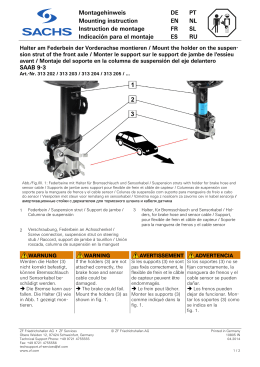
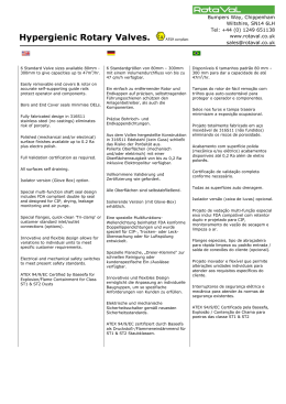
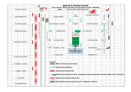
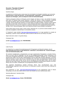
AS - 080/01
Beschleunigungs-Sensor / Acceleration Sensor /
Sensor de aceleração
2 Pin Stecker
2 pin connector
conector de 2 pinos
50,23
66,55
Sechskant
hexagonal
sextavado
SW 24
1/4" - 28 UNF
Montageöffnung
mounting hole
furo de montagem
25,4
Abb. 1
Beschleunigungs-Sensor
Fig. 1
AS080-1 (050822)
Acceleration Sensor
Imagem 1
Sensor de aceleração
Anwendung
Application
Aplicação
Der Sensor AS-080/01 wird vorzugsweise zur Messung der Schwingbeschleunigung in erhöhten Temperaturbereichen (max. 150 °C) eingesetzt.
The AS-080/01 acceleration sensor is
mainly used to measure acceleration
in high temperature applications
(max. 150 °C).
O sensor AS-080/01 é preferencialmente utilizado para medir a aceleração oscilatória em temperaturas
mais elevadas (max. 150 °C).
Messprinzip
Measuring Principle
Princípio de medição
Beschleunigungs-Sensoren arbeiten
nach dem piezo-elektrischen
Kompressionsprinzip. Im Sensor bilden
die Piezo-Keramikscheibe und eine
interne Sensormasse ein FederMasse-Dämpfungssystem.
Acceleration sensors operate in
accordance with the piezoelectric
compression principle. Inside the
sensor, a spring/mass damping
system is formed by a piezoceramic
element and an internal sensor mass.
Sensores de aceleração funcionam
segundo o princípio de compressão
piezo-eléctrico. O disco de cerâmica
piezo e uma massa sensora interna
formam, no interior do sensor, um
sistema de amortização de massa e
mola.
Werden in dieses System
Schwingungen eingeleitet, übt die
Masse eine Wechselkraft auf die
Keramikscheibe aus, wodurch infolge
des Piezo-Effektes elektrische
Ladungen entstehen, die proportional
zur Beschleunigung sind.
When introducing vibrations to this
system, the mass exerts an alternating
force on the ceramic element and, due
to the piezoelectric effect, induces an
electric charge that is proportional to
the vibration acceleration.
Quando oscilações são introduzidas
no sistema, a massa executa um força
recíproca sobre o disco de cerâmica,
originando cargas eléctricas, proporcionais à aceleração, através do efeito
piezo.
Ein integrierter Verstärker wandelt das An integrated amplifier converts this
Ladungssignal in ein nutzbares
charge signal into a usable voltage
Spannungssignal um.
signal.
Um amplificador integrado transforma
o sinal de carga num sinal de tensão
utilizável.
Brüel & Kjaer Vibro
Leydheckerstraße 10
D-64293 Darmstadt
© AS080/001DEPT 26.04.2010
C 102 800.009
Seite/Page 1 von/of/de 7
Tel. : +49 (0)6151 428-1400
Fax : +49 (0) 6151 428-1401
E-Mail : [email protected]
AS - 080/01
Technische Daten
Technical Data
Dados técnicos
Typ
Type
Tipo
piezo-elektrischer BeschleunigungsSensor mit integriertem Ladungsverstärker
Piezo-electric acceleration sensor with Sensor de aceleração piezo-eléctrico
integrated charge amplifier
com amplificador de carga integrado
Übertragungsfaktor
Transmission factor
100 mV/g
±5%
100 mV/g
Factor de transmissão
±5%
100 mV/g
±5%
3
Deviation, dB
2
1
0
-1
-2
-3
1
10
100
1000
10000
Frequency, Hz
Abb. 2
Typischer Frequenzgang
Max. Vibrationsbelastung
Fig. 2
Typical frequency response Imagem 2
Vibration limit
500 g peak
Max. Schockbelastung
5000 g peak
Arbeitstemperaturbereich
- 50 °C ... + 150 °C
Lagerungstemperaturbereich
- 50 °C ... + 150 °C
Beschleunigungsbereich
50 g peak
Linearitätsfehler Amplitude
1%
Seite/Page 2 von/of/de 7
Carga de vibrações max.
500 g peak
Shock limit
Curva de frequência
característica
500 g peak
Carga de choque max.
5000 g peak
Operating temperature range
5000 g peak
Temperatura de serviço
- 50 °C ... + 150 °C
Storage temperature range
- 50 °C ... + 150 °C
Temperatura de armazenagem
- 50 °C ... + 150 °C
Acceleration range
50 g peak
Amplitude non-linearity
1%
- 50 °C ... + 150 °C
Aceleração
50 g peak
Amplitude de erro linear
1%
© AS080/001DEPT 26.04.2010
AS - 080/01
Frequenzgang
Frequency response
± 5 % 4 ... 4000 Hz
± 10 % 3 ... 6000 Hz
(±3 dB) 1 ... 10000 Hz
Resonanzfrequenz, montiert, norm
Passagem de frequência
± 5 % 4 ... 4000 Hz
± 10 % 3 ... 6000 Hz
(±3 dB) 1 ... 10000 Hz
Resonance frequency
20 kHz
± 5 % 4 ... 4000 Hz
± 10 % 3 ... 6000 Hz
(±3 dB) 1 ... 10000 Hz
Frequência de ressonância,
montado, normalizada
20 kHz
max. Querempfindlichkeit
20 kHz
max. transverse sensitivity
5 % vom axialen
Messwert
Sensibilidade transversal max.
5 % of axial measured
value
5 % do valor de medição
axial
Rauschpegel, norm.
Electrical noise
Nível de ruído, normalizado
Breitbandrauschen
2,5 Hz bis 25 kHz
Broadband 2.5 Hz to 25 kHz
Ruído de banda larga
2,5 Hz a 25 kHz
0,3 mg
0.3 mg
Spektralrauschen bei
25 °C
0,3 mg
Spectral at
150°C
10 Hz
Ruído espectral a
25 °C
150°C
10 Hz
10 µg/√Hz
30 µg/√Hz
100 Hz
10 µg/√Hz
1000 Hz
10 µg/√Hz
30 µg/√Hz
6 µg/√Hz
Konstant-Stromversorgung IB
4 mA (2 mA ... 4 mA)
Versorgungsspannung UB
+ 24 V DC
(+ 18 V DC ...+ 30 V DC)
Ausgangsimpedanz, max.
3 µg/√Hz
bei 25 °C
bei 150 °C
10 µg/√Hz
6 µg/√Hz
Constant current supply IB
4 mA (2 mA ... 4 mA)
voltage supply UB
+ 24 V DC
(+ 18 V DC ...+ 30 V DC)
Output impedance, max
at 25 °C
at 150 °C
Dichtigkeit
12 V DC
11 V DC
15 µg/gauss
Base strain sensitivity
< 0,0005 g/(µm/m)
< 0.0005 g/(µm/m)
Sealing
hermetisch dicht
Temperaturverhalten
siehe Abbildung 3
© AS080/001DEPT 26.04.2010
2 µg/√Hz
6 µg/√Hz
Alimentação de corrente constante
IB
4 mA (2 mA ... 4 mA)
+ 24 V DC
(+ 18 V DC ...+ 30 V DC)
Impedância de saída max.
Potencial em repouso,
normalizado
Electromagnetic sensitivity
15 µg/Gauss
Dehnungsempfindlichkeit
10 µg/√Hz
100 Ω
Bias output voltage
Elektromagnetische
Empfindlichkeit
3 µg/√Hz
Tensão de alimentação max. UB
100 Ω
12 V DC
11 V DC
30 µg/√Hz
1000 Hz
2 µg/√Hz
100 Ω
Ruhepotential norm.
10 µg/√Hz
100 Hz
1000 Hz
2 µg/√Hz
150°C
10 Hz
100 Hz
3 µg/√Hz
25 °C
a 25 °C12 V DC
a 150 °C11 V DC
Sensibilidade electro-magnética
15 µg/Gauss
Sensibilidade elástica
< 0,0005 g/(µm/m)
Estanquicidade
Hermetic
Temperature response
see Figure 3
Totalmente estanque
Comportamento térmico
ver imagem 3
Seite/Page 3 von/of/de 7
AS - 080/01
Deviation, %
20
10
0
-10
-50
-25
0
25
50
75
100
125
150
Tem perature, °C
Abb. 3
TypischerTemperaturgang
Gehäuse
Fig. 3
Typical temperature
response
Imagem 3
Housing
316 L Edelstahl
Carcaça
316 L stainless steel
Masse
Weight
140 g
316 L Aço INOX
Peso
135 g
Befestigung
135 g
Mounting
Zentralbefestigung mittels
Gewindestift:
1/4" -28 UNF
Innengewinde
Steckanschluss
Montagem
Central hole mounting by
means of 1/4" -28 stud
Output connector
MIL-C-5015, 2-polig
PIN A
Ficha de conexão
PIN A
PIN B
Montagem centrada com
veio roscado:
Rosca interior 1/4" -28
2 pin, MIL-C-5015 style
Signal, Betriebsspannung
MIL-C-5015, 2 pinos
PINO A
power signal
Sinal, tensão de serviço
PIN B
Common
Comportamento
térmico característico
PINO B
common
Comum
AS-080/01
4mA
Q
U
WH
SIG
BK
COM/0V
SE
AS080-5 (020125)
Hinweis:
Advice:
Falls SE nicht vorhanden an PE
anschließen.
If SE is not available connect to PE. Em caso de não existir SE, usar PE
para a ligação.
Seite/Page 4 von/of/de 7
Atencão:
© AS080/001DEPT 26.04.2010
AS - 080/01
EMV
EMC
CEM
Störfestigkeit
Immunity to interference
Resistência ao ruído
nach DIN EN 61000-6-2
Störaussendung
as per DIN EN 61000-6-2
Emission
nach DIN EN 50081-1
WEEE-Reg.-Nr. DE 69572330
conforme DIN EN 61000-6-2
Emissão
as per DIN EN 50081-1
conforme DIN EN 50081-1
WEEE-Reg.-No. DE 69572330 WEEE-Reg.-N°. DE 69572330
Produktkategorie /
Anwendungsbereich: 9
product category /
application area: 9
catégorie de produits /
domaine d'application: 9
Zubehör
Accessories
Acessórios
AC-439 Anschlussleitung
AC-439 connecting cable
AC-439 Cabo de ligação
10 m, individuell zu kürzen
eine Seite mit Stecker
MIL C 5015, eine Seite offen
10 m, adjustable by customer
one side with connector
MIL-C-5015 one side open
10 m, para cortar à medida
um lado com ficha MIL C 5015,
um lado livre
Montage
Mounting
Montagem
Ankopplung
Coupling
Acoplagem
Grundsätzlich gilt:
General rule:
Regra geral:
Das Gewicht des BeschleunigungsSensors sollte wenigstens zehnmal
kleiner sein als das schwingungstechnisch relevante Gewicht des Messobjektes, an das er montiert ist.
The weight of the acceleration sensor
should be at least ten times lower than
the technically vibrating weight of the
object being measured and to which
the sensor is attached.
O peso do sensor de aceleracão
deveria ser, no mínimo, 10 vezes
inferior ao peso relevante para a
vibração do objecto de medição no
qual é montado.
Begründung
Basis:
Justificação
Der Beschleunigungs-Sensor ist eine
Zusatzmasse, welche das Messobjekt
belastet und dessen Schwingverhalten
ändert.
The acceleration sensor is an
additional parasitic mass which loads
the object being measured and
changes the vibration behaviour.
O sensor de aceleração significa
massa adicional para o objecto de
medição, tendo influência no
comportamento vibratório deste.
Montage
Steckverbinder
Mounting of plug
connector
Montagem Conector
Hinweis
Note
Aviso:
Bei der Montage des Steckverbinders
der Anschlussleitung AC-439 ist auf
folgendes zu achten:
When connecting the plug of the
AC-439 note the following:
Na montagem do cabo AC-439 voce
deve verificar as conecçoes e as
roscas se estao sem residuos para
nao haver problema de travamentos
por parte do conector.
Das Gewinde und die Dichtfläche
des Sensors einfetten bevor der
Steckverbinder aufgeschraubt wird,
sonst besteht die Gefahr, dass
Steckverbinder und Sensor
verkleben.
Before screwing the plug on to the
sensor connection socket, add a
little grease to the thread and the
sealing surface otherwise there is
the danger that the plug and sensor
will adhere to one another.
Sera necessario colocar entre a
rosca do conector e sua base uma
quantidade de graxa suficiente para
evitar o travamento da mesma
quando da sua remoçao.
© AS080/001DEPT 26.04.2010
Seite/Page 5 von/of/de 7
AS - 080/01
•
Beschleunigungs-Sensor
montieren
Mounting of acceleration
sensor
Montagem do sensor de
aceleração
Hinweis:
Note:
Aviso:
Der Beschleunigungs-Sensor benötigt
eine kraftschlüssige, kontaktresonanzfreie und steife Befestigung am
Messobjekt, insbesondere für
Messungen bei hohen Frequenzen.
The acceleration sensor requires a
friction-locked, contact resonance-free
and rigid mounting to the measuring
object, especially for measurement of
high frequencies.
O sensor de aceleração requer uma
fixação firme, livre de ressonâncias e
rígida no objecto de medição,
especialmente quando se destina a
medir frequências muito elevadas.
Der AS-080/01 ist mit dem
beigefügten Gewindestift zu
montieren.
Wahlweise:
•
AS-080/01 is to be mounted with
the threaded stud supplied.
Selectable:
• Gewindestift 1/4"-28 UNF
Die Einbaulage ist beliebig
•
Montar o sensor AS-080/01 com o
veio roscado juntamente fornecido.
Alternativas:
• Stud 1/4’’ -28 UNF
• Veio roscado 1/4"-28 UNF
The sensor can be mounted in any
position.
A posição de montagem é de livre
escolha
Beschleunigungs-Sensor
Acceleration Sensor
Sensor de aceleração
AS-080/01
90°
max. Einschraubtiefe
max. reach of screw
Profundidade de inserção max.
5
12
15
*0,8
Montagefläche
Mounting surface
Superfície de montagem
Gewindestift mit LOCTITE gesichert
Threaded stud secured with LOCTITE
Veio roscado egurado com LOCTITE
1/4"
28 UNF
> ø28
Abb. 4
Montage
Seite/Page 6 von/of/de 7
Fig. 4
Mounting
AS080-3 (050822)
Imagem 4
Montagem
© AS080/001DEPT 26.04.2010
AS - 080/01
•
Die Montagefläche muss im
Bereich des AS-080/01 plan und
bearbeitet sein
•
The mounting surface in the area
of AS-080/01 must be flat and
machined.
•
A superfície de montagem deve
ser nivelada e preparada na área
do sensor AS-080/01.
•
Montagefläche mit Gewindebohrung 1/4“ -28, 12 mm tief
versehen
•
Prepare the mounting surface with
an 1/4" -28 threaded hole 12 mm
deep.
•
Executar furo com rosca 1/4" 28,
profundidade 12 mm, na superfície
de montagem.
•
Dünne Schicht Silikonfett auf die
Montagefläche auftragen, um
Kontaktresonanz zu verringern.
•
Apply a thin film of silicone grease
to the mounting surface to prevent
contact resonance.
•
Aplicar uma camada fina de
gordura de silicone na superfície
de montagem, para evitar
ressonâncias de contacto.
•
Gewindestift 1/4" -28 gemäß Abb.
4 in Montagefläche einschrauben
und sichern z.B. LOCTITE 243
mittelfest, LOCTITE 270 hochfest
•
Screw the stud into the mounting
surface in accordance with fig. 4
and secure it
(e.g. with LOCTITE 243 mediumbond, LOCTITE 270 heavy-duty
bond).
•
Atarraxar o veio roscado 1/4" -28
na superfície de montagem (ver
imagem 4). Segurar o veio, por
exemplo, com LOCTITE 243,
contacto médio, ou LOCTITE 270,
contacto forte.
•
Max. Einschraubtiefe ≤ 5 mm für
Beschleunigungs-Sensor einhalten
•
Max. protrudance of the stud
≤ 5 mm for acceleration sensors
must be observed.
•
Respeitar a profundidade de
inserção max. do veio, ≤ 5 mm,
para poder montar o sensor de
aceleração.
•
AS-080/01 auf Gewindestift
•
aufschrauben
Max. Anzugsmoment entsprechend
Gewindestift beachten.
Screw AS-080/01 onto the stud.
Observe max. tightening torque in
accordance with the stud.
•
Atarraxar o sensor AS-080/01 no
veio roscado. Respeitar o
momento de aperto máximo do
veio roscado.
© AS080/001DEPT 26.04.2010
Seite/Page 7 von/of/de 7
Baixar