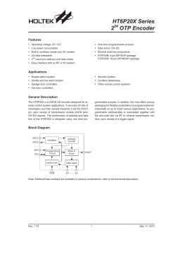
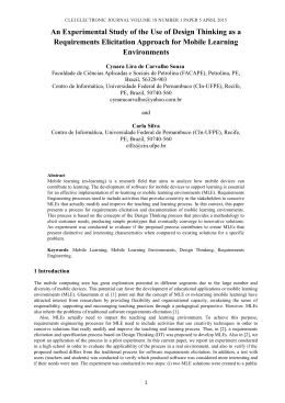
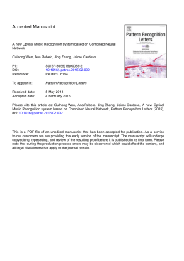
Using the Language Extended Lexicon to Support
Non-Functional Requirements Elicitation
Luiz Marcio Cysneiros, Julio César Sampaio do Prado Leite
Dep. of Computer Science-University of Toronto, Dep. de Informática PUC- Rio
[email protected], [email protected]
Abstract. Although Non-Functional Requirements (NFR) have been present
in many software development methods, they have been faced as a second or
even third class type of requirement, frequently hided inside notes and therefore
frequently neglected or forgotten. Surprisingly, despite the fact that nonfunctional requirements (NFR) are among the most expensive and difficult to
deal with [5] [12] [3][10], even today there are only a few works that focus on
NFR as first class requirements (e.g. [7][8] [10]. Not so surprisingly,
stakeholders’ demand for NFR has been continuously increasing. During 2001
edition of ICSE Mantis Chen from ACD System presented the 3 most important
aspects for a software in the stakeholders’ point of view and the 3 most
important one in the developers’ point of view. All the 6 were non-functional
requirements. This work intends to show how we used the Language Extended
Lexicon as a way of supporting initial NFR elicitation.
Keywords: Non-Functional Requirements, Language Extended Lexicon
1. Introduction
Recent research has pointed out that conceptual models need to model goals, in
order to capture the intentions which underlie complex situations within an
organisational context [11] [27] [25]. One important type of goal, namely nonfunctional requirement, is focused on how the software must do something instead of
on what the software must do.
Besides that, the more the software complexity grows, the more the stakeholders
demands new features in the software. They are not any more satisfied if the software
can meet the functional requirements. The strongly enforces NFR to be accomplished
by the software.as: cost, reliability, security, maintainability, portability, and accuracy
among others. These NFR should be dealt with since the early stages of the software
development process [7][8] [9], throughout the whole life cycle.
Some software development methods have been mentioning NFRs, among other
ways, as constraints or quality attributes of software. However, they tackle NFRs,
when they do, very superficially, frequently hiding them somewhere in the software
specification as comments. Consequently NFRs are frequently neglected or even
forgotten leading to changes in software that will take place after the software was
deployed and therefore to a very expensive and time-consuming effort [7][10].
Not eliciting NFR or doing it inefficiently has led to a series of histories reporting
failures in software development [3][18], including the very well known case of the
139
London Ambulance System [14] where the deactivation of the system right after its
deployment was strongly influenced by NFR non-compliance. Studies point out these
requirements as being among the most expensive and difficult to correct [5] [12] [9].
In spite of its importance, NFR have surprisingly received little attention in the
literature and are much poorly understood than other less critical aspects of the
software development [8]. The majority of the works on NFR use a product-oriented
approach, which is concerned only with how much a software is in accordance with
the set of NFR that it should satisfy [16] [1] [13] [23] [22].
Although these works have added an important amount of knowledge on how to
deal with NFR they added almost nothing to the aspect of how to elicit NFR. In this
paper we introduce the concept of using the Language Extended Lexicon (LEL) [19]
as tool for supporting the initial NFR elicitation. The use of the lexicon is part of a
larger approach on dealing with NFR [10] that due to the lack of space will be only
introduced here.
Section 2 will sketch the overall strategy to deal with NFR while Section 4 will
focus on the use of the LEL in the early stages of NFR elicitation. Section 4 will
conclude and show some future work.
2. An Overview of the Strategy to Deal with NFR
This section overviews the complete strategy that we propose to deal with NFR.
Although we are showing here the entire strategy, due to the lack of space we will
cover in this paper just the part of the strategy related to how to bring NFR into use
cases diagrams and scenario models.
As previously mentioned, we consider the software development process
comprising two independent evolutionary cycles that may be dealt with separately,
since we propose to establish convergence points between both cycles. Through the
use of these convergence points we can express in the functional view all the actions
and data that will be necessary to satisfice the NFR tackled in the non-functional
view.
Figure 1 shows the idea of these two views as well as its convergence points.
The so-called functional view includes some of the artifacts commonly used in the
software development process, while the non-functional view uses the NFR
Framework [8] to represent the NFR found.
We will not focus on any particular approach to build the conceptual models of the
functional view. We understand that our strategy may fit to any approach one decides
to use.
As portrait in figure 1, we propose to build both the functional and the nonfunctional views anchored in the Language Extended Lexicon (LEL) [19]. This will
lead to a smooth integration between both views. Therefore, building the Lexicon will
be the first thing to be carried out in this strategy.
The objective of the LEL is to register the vocabulary of a given UofD1. It is based
upon the following simple idea: understand the problem’s language without worrying
1
“Universe of Discourse is the general context where the software should be developed and operated. The
UofD includes all the sources of information and all known people related to the software. These people
are also known as the actors in this UofD.”
140
about understanding the problem [19]. The main objective of the LEL is to register
signs (words or phrases) peculiar to a specific field of application.
Building the non-functional view departs from the use of an existing LEL. In order
to aid on this process we have extended the LEL to help NFR elicitation. The LEL is
now structured to express that one or more NFR is needed by a symbol. It is also
structured to handle dependency links between one NFR and all the notions and
behavioral responses that are necessary to satisfice this NFR. Section 3 will detail
Sequence
Diagram
Functional View
Class
Diagram
Use
UseCases
Cases
Collaboration
Diagram
Scenarios
New
Actors
and New
Use Cases
LEL
New Episodes,
Resources and
Actors
New Classes,
Operations and
Attributes
New Classes
and Messages
NFR and its
Impacts (Positives
and Negatives)
NFR
Graph
Non-Functional View
that.
Figure 1 – An Overview of the Strategy to Deal With NFR
The first step on building the non-functional view will be to enhance the existing
LEL with the NFR that are desired by the stakeholders. To do that, we will run
through all the LEL symbols using the knowledge base on NFR present in the
OORNF tools to ask ourselves and the stakeholder (whenever possible) if any of the
NFR present in this knowledge base may be necessary to each of the LEL symbols.
Each NFR found may be represented in the symbol.
After representing the need for an NFR the software engineer has to ask himself
and the stakeholders what should be necessary to do to satisfice this NFR. Again, the
knowledge base in the OORNF tool may be used. All the information that arises from
this questioning may be represented in the LEL either in the same symbol or in
another symbol if necessary.
Although the LEL can now handle some representation of the NFR and its
impacts, it is not the best tool to deal with them in a more complete way, so one can
reason about their interdependencies and conduct the necessary tradeoffs that arises
during this process. To fully represent and reason with NFR we propose to use the
NFR Framework proposed by Chung [6] with some slights adaptations.
141
The NFR Framework [24][6][8] faces NFR as softgoals that might conflict among
each other and must be represented as softgoals to be satisficed. Each softgoal will be
decomposed into sub-goals represented by a graph structure inspired by the and/or
trees used in problem solving. This process continues until the requirements engineer
considers the softgoal satisficed (operationalized) [8], so these satisficing goals can be
faced as operationalizations of the NFR.
Another way of understanding
operationalizations is that they are, in fact, functional requirements that have arisen
from the need to satisfice NFR.
An NFR has a type that refers to a particular NFR as for example security or
accuracy. It also has a subject matter or topic, for example room showed in figure 2,
which portrays an NFR graph that specifies a light control software extracted from
one of our case studies.
The NFR framework was extended to represent the operationalizations in two
different ways. The first one we called dynamic operationalizations. This type of
operationalizations can be faced as those that ask for abstract concepts and usually
calls for some action to be carried out. The second one we called static
operationalizations and usually expresses the need for some data to be used in the
design of the software to store information that is necessary for satisficing the NFR
[10]. Figure 2 shows an example of an NFR graph where we can see these two types
of operationalizations.
S
S
S
Safety
[Room]
Safety
[Room.
Light scene.
Current light scene >=
Safe Illumination]
Safety
[Room.
Light Scene.
Safe Illumination=14 lux]
S
Safety
[Room.
Malfunction.
Ols]
S
Safety
[Room.
Malfunction]
S
Safety
[Room..
Malfunction of OLS.
All CLG set on]
S
S
Safety
[Room.
Malfunction.
Motion Detector]
Safety
[Room.
Malfunction.
User.
Get informed]v
S
S
Safety
[Room.
Malfunction.
FM
Get informed]
Safety
[Room.
Malfunction.
Motion Detector.
Set room as occupied]
Figure 2. An Example of a NFR Graph
On the top of the figure 2 we can see the node that represents the root of this graph
represented as Safety[Room], meaning that room is a place that has to be safe
regarding illumination aspects. One of the operationalizations that represent part of
this NFR satisficing can be seen on the left side of the figure represented by a bold
circle denoting a static operationalization. Here, we can see the need of some
information in the system that represents the minimum illumination in lux that can be
used in a room. Some dotted circles appear on the bottom of the figure representing
dynamic operationalizations. One of them, Safety[Room.Malfunction.User get
142
informed], represents that the user may be informed of any malfunction that occurs in
the room. The letter S inside each node represents that this sub-goal is Satisficed. The
letter P can also be used for those ones that are Partially satisfied or D for those ones
that are Denied. Further details can be seen in [10].
It is important to call attention for the fact that the identifier that appears close to
the NFR on the root of the graph (NFR Topic) has necessarily to be a symbol of the
LEL. In figure 2 we see that the root node is represented by Safety[Room], so room
has to be a symbol of the LEL. If one cannot find the word or sentence intended to be
used as a topic for an NFR either one symbol represented in the LEL has an alias not
defined or the LEL is incomplete and may therefore be updated.
To build the NFR model we will search every entry of the LEL looking for
notions that express the need for an NFR. For each NFR found, we must create an
NFR graph expressing all the operationalizations that are necessary to satisfice this
NFR. At the end of this process we will therefore have a set of NFR graphs that will
represent the non-functional aspects of the system.
Once we have this set of NFR ready, we have to look for possible
interdependencies, positive or negative, among NFRs. It is important to stick out that
all the effort on NFR tradeoffs due to positive and negative interdependencies will
take place in the non-functional view, i.e., using the NFR framework. What will be
integrated into the functional view will be the result that one gets after all the
necessary reasoning on NFR interdependencies and its consequences.
Further details on constructing the non-functional view can be seen in [11] and
partially in [10].
To integrate the functional and non-functional views we propose a process to drive
the operationalizations that are represented in the set of NFR graphs in the nonfunctional view to the functional view. The integration process can take place either
in the early phases, integrating the NFR into the use case or scenario models, or later,
integrating NFR into class, sequence and collaboration diagrams.
Notice that we do not propose to deal with NFR in any of these models. NFR’s
satisficing usually requires a very detailed reasoning to reach its operationalizations.
Also, one NFR frequently presents many interdependencies with other NFRs. Dealing
with these particular aspects of NFRs can be quite difficult to be accomplished
directly in use cases, scenarios or even class diagrams. Thus, we propose to deal with
NFR in the NFR view using the approach we described to build the non-functional
view, and then to integrate the operationalizations found into the models used in the
functional view. We also propose a traceability mechanism to make it easier to
navigate between models.
Due to the lack of space, this work will detail only the integration process that
drives NFR to the use cases and scenario models. Further details on integrating the
NFR into the class, state and collaboration diagrams can be seen in [11] and partially
in [10].
3. Using the LEL to support NFR elicitation on earlier phases
The LEL is based on a code system composed of symbols where each symbol is
an entry expressed in terms of notions and behavioral responses. The notions must try
to elicit the meaning of the symbol and its fundamental relations with other entries.
143
The behavioral response must specify the connotation of the symbol in UofD. Each
symbol may also be represented by one or more aliases.
The construction of the LEL must be oriented by the minimum vocabulary and the
circularity principles. The circularity principle prescribes the maximization of the
usage of LEL symbols when describing LEL entries while the minimal vocabulary
principle prescribes the minimization of the usage of symbols exterior to the LEL
when describing LEL entries. Because of the circularity principle, the LEL has a
hypertext form. Figure 4 shows an example of an entry in the LEL.
It is important to make it clear that the LEL is not restricted to holding information
related to functional requirements. Its idea is to register the entire vocabulary in the
UofD and therefore it might also include the non-functional aspects of the domain.
Although the LEL can handle non-functional aspects of the domain, at least the
very first version of the LEL is usually mainly composed of symbols related to
functional requirements. This is due to the very abstract nature of non-functional
requirements and because quality aspects, in spite of its importance, are usually
hidden in everyone’s mind. However, it does not mean that the software engineer
cannot register information about non-functional requirements. A well-defined set of
symbols representing the vocabulary of the UofD is a key point to the strategy.
Building the non-functional view, depicted in figure 3, departs from the use of an
existing LEL. In order to aid on this process we have extended the LEL to help NFR
elicitation. The LEL is now structured to express that one or more NFR is needed by a
symbol. It is also structured to handle dependency links between one NFR and all the
notions and behavioral responses that are necessary to satisfice this NFR. Figure 3
shows these new features of the LEL.
Client
Changes due to Conflict
Resolution
Knowledge on
the Problem
Introduce NFRs
in the LEL
New Notions
New Behavioral Responses
New Symbols
Positive and Negative Influences
Conflicts
Design Decisions
NFR
Graph
LEL with
NFRs
1
LEL
Symbol
LAL
LEL
Identify and
Solve
Conflicts
Represent
NFR
2
3
Primary NFR
Knowledge
Base on
NFRs
Interdependencies
Figure 3. Building the Non-Functional view
We have extended the LEL to help NFR elicitation. The LEL is now structured to
express that one or more NFR is needed by a symbol. It is also structured to handle
dependency links between one NFR and all the notions and behavioral responses that
are necessary to satisfice this NFR. Figure 4 shows these new features of the LEL.
We have extended the OORNF tool [26] to support these extensions. This tool was
originally developed to support the requirements baseline proposed by Leite [20] with
144
some NFR support.
The tool has also a knowledge base on NFR that can and must be constantly
updated. This knowledge base stores a variety of NFR and some common way to
decompose them. The tool brings along with the definition of these NFR a set of
possible conflicting NFR as well as a set of NFR that may be positively impacted by
this NFR.
The OORNF tool still supports for entering the LEL, scenarios and CRC cards
together with a support to create the scenarios from the LEL entries [15] and the CRC
cards from the LEL entries and the elicited scenarios [21].
As we can see in figure 3, the first step on building the non-functional view will
be to enhance the existing LEL with the NFR that are desired by the stakeholders. To
do that, we will run through all the LEL symbols using the knowledge base on NFR
present in the OORNF tools to ask ourselves and the stakeholder (whenever possible)
if any of the NFR present in this knowledge base may be necessary to each of the
LEL symbols. Each NFR found may be represented in the symbol.
Picking up an example drawn from a case study performed within a clinical
analysis laboratory, we would go through all the symbols represented in the LEL
asking ourselves and the stakeholders whenever possible, what possible NFR would
have to be achieved so we that symbol can be completely represented. In this process,
we will use the knowledge base in the OORNF tool to help us on this questioning.
Figure 4 shows the symbol Sample belonging to a Clinical Analysis Laboratory
information system. The figure shows the notions and behavioral responses to this
symbol before we carried out an analysis for eventual NFR that might be necessary to
this symbol.
Figure 4. One Entry of a Symbol Before Analyzing it for NFR
145
Once we got to this symbol we used the NFR knowledge base of the OORNF tool
to ask ourselves and the stakeholders, if NFR would apply to this symbol. Figure 5
illustrates the use of this knowledge base. Figure 6 shows the resultant symbol after
we came up to the conclusion that traceability was essential to that symbol, once the
can not afford to loose a sample. In this figure it is possible to see in its notions the
need for the traceability NFR.
Figure 5. Using the Knowledge Base to Help Eliciting
146
Figure 6. Symbol After One NFR was Picked up
Now that we came up with the need for traceability to Samples we have to reason
about how this might be achieved. One way of doing that could be to use the
knowledge base on the OORNF tool where one can find some of the decompositions
methods mentioned in [8], or we can simply ask ourselves and the stakeholders how
could we guarantee this traceability to work. One of the answers was that every time a
sample is aliquoted (draw from one recipient to another) this procedure has to be
documented in the software so one can know which sample was originated from
another sample. We represented this answer as an entry in the behavioral responses of
the symbol Aliquote sample and then established a dependency link between this
behavioral response and the NFR traceability stated in the notions of the symbol
Sample. The other answer we got was that one should be able to know where a
sample is at any time is needed. We can see these two answers represented in figure 7,
respectively as a behavioral response in the Aliquote sample symbol and in the
Sample symbol itself.
Better thinking about the behavioral response we placed in the symbol Sample we
can see that this answer is not sufficient to achieve the traceability NFR cause we do
not specify how one can know where a sample is at any time is needed. Again we ask
ourselves how to solve this problem and we decide that in order to know the exact
position of a sample at a time it is necessary to scan this sample every time it is
transported from one place to another. To represent that need we created a new
symbol called Scan Sample that can be seen in figure 8.
Symbol
Symbol
Notions
Notions
Behavioral Responses
Behavioral Responses
Figure 7. Consequences of Satisfying the NFR of the Symbol Sample.
147
Figure 8. A Symbol Created to Satisfice a NFR From Another Symbol
This process is repeated for all the symbols presented in the LEL. Once we have
finished it, all the NFR represented in the LEL will have to be represented using the
NFR graphs as in the NFR Framework [7], as exemplified in figure 2. We do that
because although the LEL plays an important role on finding NFR its is suitable to
fully deal with them. Dealing with NFR calls for a very complex process of
negotiation once they are often conflicting among them. Therefore representing and
reasoning about all the interdependencies of NFR are left for a further step now using
the NFR graphs.
The LEL will yet play an important role helping to build these NFR Graphs.
To build the NFR graphs, one should search every entry of the LEL looking for
notions that express the need for an NFR. For each NFR found one must create an
NFR graph where this NFR will be the root of the graph. This graph must be further
decompose so it expresses all the operationalizations that are necessary to satisfice
this NFR
Lets take the symbol Room belonging to a Light Control System. One NFR we
would find in the notions of this symbol would be Safety once the system must assure
that it will behave always in a safe way regarding the amount of illumination in a
room. Figure 9 shows the entry for this symbol and illustrates how a NFR graph
would be originated from there, while figure 10 shows the use of NFR navigation
from the OORNF tool where we can see the notions and behavioral responses that
were add to satisfice the NFR showed in figure 9. In this case there were only
behavioral responses.
After we represent the NFR graph root we have find out its operationalizations.
We can do it by either using the decomposition methods proposed by Chung [8] or
148
using the OORNF tool to exam what notions and behavioral responses were add to
the LEL to satisfice NFR. These notions and behavioral responses will be candidates
to operationalizations of this NFR. These two approaches are not conflicting; actually
they are more likely to be used together.
Safety [Room]
Figure 9. Creating an NFR graph
Figure 10. Navigating a NFR to Find its Operationalizations
Using the behavioral responses showed in figure 10 we would them represent the
operationalizations of the Safety NFR regarding room as can be seen in figure 11.
Once we have done that, we must now try to see what possible sub-goals, if any,
would represent an intermediary step between the graph root and its
operationaliazations.
We may proceed in two different ways:
149
1) Decomposing the root in a top-down approach. For example, we could
decided that to achieve the operationalizations that states that the safe
illumination is equal to 14 lux, we should first decompose the NFR Safety
[Room] into a sub-goal Safety [Room.Light Scene] representing that to a room
be safe we have to assure that any possible light scene will be safe. We should
also decompose it again representing that to satisfice it we have to assure that
the Current Light Scene will always be equal or greater then the safe
illumination.
2) We can proceed the evaluation in a bottom-up approach. For example, take
both the operationalization that states that in the case of a malfunction of an
outside light sensor (OLS) all the ceiling light groups (CLG) must be turned
on and the operationalization that states that the user of the room must be
informed of a malfunction. We can visualize that these two operationalizations
points out to an intermediary sub-goal that decomposes the Safety [Room]
NFR in a sub-goal regarding any malfunctions Safety [Room. Malfunction].
Figure 3 shows the final version of this graph.
Safety
[Room]
S
S
Safety
[Room.
Light Scene.
Safe Illumination=14lux]
S
Safety
[Malfunction of OLS.
All CLG set on]
S
Safety
[Malfunction.
User.
Get informed]
S
Safety
[Located Near the Door]
Figure 11. A First Approach to Decomposing an NFR
After we have carried out this process for each of the LEL symbols, we will have
a set of NFR graphs that will compose the non-functional view.
4. Conclusion
Companies are now facing an environment that calls for more complex business
strategies and flexible structures in order to be adaptable to a changing world. This
has to be supported by software that becomes each day more complex and hence
much more difficult to specify. To deal with such complex conceptual models we
have to be able, among other things, to deal with NFR [25].
It has been shown that NFR must be dealt with since the early stages of software
development [7][8][10] and that errors due to not dealing with NFRs are among the
most expensive and difficult to deal with [5][12][9][10].
We introduced in this paper a strategy to deal with NFRs and detailed the use of
the LEL as a tool on helping the NFR elicitation, which is still a very opened subject
in requirements elicitation, since most of the work on NFR are more focused on
dealing and representing NFR then on how to search for them [8][2] [17].
150
We have used this process as part of three case studies we have carried out and in
all of them its use was very helpful on finding NFR and its operationalizations. It is
important to emphasize that one of these cases studies was a real case one where we
had the opportunity to interact with real stakeholder.
This case study was conducted together with a software house specialized in
building software for clinical analysis laboratories. They were responsible for
developing a new information system to a laboratory. They built a conceptual model,
which expressed the software requirements in their point of view. One of the authors
of this paper acted as the second team in this case study and built the non-functional
view by making use of structured interviews with some of the stakeholders and by
using some available documentation as ISO 9000 quality manuals. Once the nonfunctional view was ready, we used the integration process briefly described in
Section 2 to eventually find out new classes, operations and attributes that have arisen
from this integration.
Although we have not measured the overhead of the use of the LEL alone, we
have measured the overhead of the introduction of the strategy as a whole. In order to
measure the overhead of using the proposed strategy, we first measured the time spent
by software house team from the Case Study III from the initial phases of the software
development to the end of the conceptual model. They consumed a total of 1728
hrs/man of work. On the other hand, we measured the time we took to build the nonfunctional view and integrate it to the conceptual models. We consumed 121 hrs/man
to do that. Therefore, we state that the estimated overhead is 7%. This number is also
coherent with the overhead found (10%) in the case studies of [10]. The difference
can be result from either the lack of accuracy in the measurement or to improvements
introduced to the strategy.
The use of the LEL inside the scope of the OORNF tool was very well accepted
and understood by the stakeholders. As these stakeholders were business managers
and high level employees from the health care domain we believe that being able to
use the LEL and the with them clearly suggest that its use can be suitable to carried
out in many other domains.
Future work will enclose the investigation of possible ways of automating the
NFR graphs generation direct from the OORNF tool as well as which possible
artificial intelligence techniques could be applied to enhance interdependencies
detection among the NFR using the causal links among symbols.
5 – Bibliography
[1] Boehm, B. “Characteristics of Software Quality” North Holland Press, 1978.
[2] Boehm, Barry e In, Hoh. “Identifying Quality-Requirement Conflicts”. IEEE
Software, March 1996, pp. 25-35.
[3] Breitman,Karin Koogan, Leite J.C.S.P. e Finkelstein Anthony. The World's Stage: A
Survey on Requirements Engineering Using a Real-Life Case Study. Journal of the
Brazilian Computer Society No 1 Vol. 6 Jul. 1999 pp:13:37.
[4] Breitman, K.K. "Evolução de Cenários" Tese de Doutorado submetida na PUCRio em Maio de 2000.
[5] Brooks Jr.,F.P."No Silver Bullet: Essences and Accidents of Software
Engineering" IEEE Computer Apr 1987, No 4 pp:10-19, 1987.
151
[6] Chung L., “Representing and Using Non-Functional Requirements: A Process
Oriented Approach” Ph.D. Thesis, Dept. of Comp.. Science. University of
Toronto, June 1993. Also tech. Rep. DKBS-TR-91-1.
[7] Chung, L., Nixon, B. “Dealing with Non-Functional Requirements: Three
Experimental Studies of a Process-Oriented Approach” Proc. 17th Int. Con. on
Software Eng. Seatle, Washington, April pp: 24-28, 1995.
[8] Chung, L., Nixon, B., Yu, E. and Mylopoulos,J. “Non-Functional Requirements
in Software Engineering” Kluwer Academic Publishers 2000.
[9] Cysneiros, L.M. and Leite, J.C.S.P. “Integrating Non-Functional Requirements
into data model” 4th International Symposium on Requirements Engineering –
Ireland June 1999.
[10] Cysneiros,L.M., Leite, J.C.S.P. and Neto, J.S.M. “A Framework for Integrating
Non-Functional Requirements into Conceptual Models” Requirements
Engineering Journal – Vol 6 , Issue 2 Apr. 2001, pp:97-115.
[11] Cysneiros, L.M. “Requisitos Não Funcionais: Da elicitação ao Modelo
Conceitual” Ph.D. Thesis, Dept. de Informática PUC-Rio, feb 2001.
[12] Davis, A. "Software Requirements: Objects Functions and States" Prentice Hall,
1993.
[13] Fenton, N.E. and Pfleeger, S.L. "Software Metrics: A Rigorous and Practical
Approach" 2nd ed., International Thomson Computer Press, 1997.
[14] Finkelstein, A. and Dowell J. “A comedy of Errors: The London Ambulance
Service Case Study” Proceedings of the Eighth International Workshop on
Software Specification and Design, IEEE Computer Society Press pp 2-5 1996.
[15] Hadad, Graciela et. al. “Construcción de Escenarios a partir del Léxico
Extendido del Lenguage” JAIIO'97, Buenos Aires, 1997, pp. 65-77.
[16] Keller, S.E. et al “Specifying Software Quality Requirements with Metrics” in
Tutorial System and Software Requirements Engineering IEEE Computer
Society Press 1990 pp:145-163.
[17] Kirner T.G. , Davis A .M. , “Nonfunctional Requirements of Real-Time
Systems”, Advances in Computers, Vol 42 pp 1-37 1996.
[18] Lindstrom, D.R. “Five Ways to Destroy a Development Project” IEEE Software,
September 1993, pp. 55-58.
[19] Leite J.C.S.P. and Franco, A.P.M. “A Strategy for Conceptual Model
Acquisition ” in Proceedings of the First IEEE International Symposium on
Requirements Engineering, SanDiego, Ca, IEEE Computer Society Press, pp
243-246 1993.
[20] Leite J.C.S.P., Oliveira, A.P.A., “A Client Oriented Requirements Baseline",
Proc of the 2nd IEEE International Conference on Requirements Engineering,
Computer Society Press, 1995, pp. 108-115.
[21] Leonardi, Carmen. et. al. “Una Estrategia de Análisis Orientada a Objetos
basada en Escenarios” Actas II Jornadas de Ingeniaria de Software JIS97,
[22] Lyu, M.R. (ed.) "Handbook of Software Reliability Engineering" McGraw-Hill,
1996.
[23] Musa, J., Lannino, A. and Okumoto, K. "Software Reliability: Measurment,
Prediciton, Application" New York, McGraw-Hill, 1987.
152
[24] Mylopoulos,J. Chung, L., Yu, E. and Nixon, B., “Representing and Using Nonfunctional Requirements: A Process-Oriented Approach”, IEEE Trans. on
Software Eng, 18(6), pp:483-497, June 1992.
[25] Mylopoulos, J. “Capturing Intentions in Requirements engineering: A modeling
Perspective” Invited Talk at the IFIP WG 2.9 meeting, Bramshill, UK, March
1995.
[26] Neto, J.S.M. "Integrando Requisitos Não Funcionais ao Modelo de Objetos"
M.Sc. Dissertation Submitted to the Computer Science Department of PUCRio, Mar/2000.
[27] Yu, Eric “Towards Modelling and Reasoning Support for Early-Phase
Requirements Engineering” Proc. of the 3rd International. Symposium. on
Requirements Eng. Jan 1997 pp:226-235.
153
Baixar