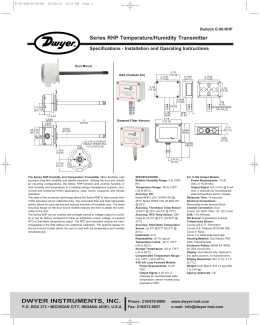
TERMOSTATO DIFERENCIAL
PARA AQUECIMENTO SOLAR
MICROSOL
VERSÃO 05
R
CONTROLS
Encontre os manuais de toda linha, via Internet, em:
www.fullgauge.com
[email protected]
GENUINAMENTE BRASILEIRA
Fone/Fax: (51) 475 3308
R
CONTROLS
O MICROSOL comanda uma bomba de circulação de água através do diferencial de
temperatura entre os coletores solares e o reservatório térmico, ou piscinas.
Por ser um instrumento dedicado o MICROSOL possui 14 funções protegidas por código de
acesso que garantem melhorar a captação de energia solar, evitar o congelamento nos tubos
durante o inverno e controlar o superaquecimento.
-Alimentação: 220VCA (direta, com transformador interno)
Outras disponíveis sob especificação: 127 VCA,12 VCA/CC
1
BRANCO
PRETO
PRETO
2. ESPECIFICAÇÕES TÉCNICAS
AMARELO
Dimensão do furo
para fixação do instrumento
Ø 60 mm
5. CONEXÕES ELÉTRICAS
1. DESCRIÇÃO
Fio Roxo
2
Sensor 1
-Temperatura de controle: -9.9 a 99.9°C
3
Sensor 2
BOMBA
Acima da corrente especificada
utilize contatora.
Sensor 3
-Resolução: 0.1°C
Alimentação
Elétrica
-Corrente máxima: 10 Amperes (carga resistiva)
-Dimensões: Diâmetro
60mm / Profundidade
40mm
-Temperatura de operação: 0 a 60 ºC
-Umidade de operação: 10 a 90% UR (sem condensação)
Nota: O comprimento do cabo do sensor é de 2,5 metros pode ser aumentado pelo
próprio usuário, até 200 metros.
Para o sensor 1 utilize cabo coaxial tipo microfone 2 x 0,14mm²
Para o sensor 2 e 3 utilize cabo coaxial tipo microfone 1 x 0,14mm²
Para imersão em água utilize poço termométrico.
Esquema de ligação de supressores
em contatoras
IMPORTANTE
A1
Supressor
Conforme capítulos da norma NBR 5410:
1: Instale protetores contra sobretensões na alimentação
2: Cabos de sensores e de sinais de computador podem estar juntos, porém não no
mesmo eletroduto por onde passam alimentação elétrica e acionamento de cargas
A1 e A2 são os bornes da
bobina da contatora.
Esquema de ligação de supressores
em cargas acionamento direto
Supressor
3: Instale supressores de transientes (filtro RC) em paralelo às cargas, como forma
de aumentar a vida útil dos relés.
Mais informações contate o nosso departamento de Eng. de Aplicação através do
e-mail eng-aplicacao@ fullgauge.com.br ou pelo telefone (51) 4753308.
A2
Carga
Para acionamento direto leve em
consideração a corrente máxima
especificada.
2
7
3. CONFIGURAÇÃO
IMPORTANTE: ( * ) O valor ajustado na função
deve ser, obrigatoriamente, maior que o
ajustado na função
. Assim sendo, o MICROSOL não permite que sejam feitos ajustes inválidos
afim de garantir o seu perfeito funcionamento.
EX.: Configuração atual
Primeiramente ajuste
{
10,0°C
Você deseja alterar para
5,0°C
para 2,0°C, e logo após ajuste
{
3.1 Para entrar no menu de funções:
4,0°C
a) Pressione a tecla
b) Ao aparecer
2,0°
, pressione
através das teclas
para 4,0°C.
c) Através das teclas
( ** ) Só podem ser visualizadas no menu, se o terceiro sensor estiver habilitado.
por 2 segundos até aparecer
SET
e
SET
(toque curto) e insira o código de acesso (123)
. Para confirmar pressione
e
, soltando em seguida.
SET
acesse as demais funções e proceda do mesmo modo
para ajusta-las.
d) Para sair do menu e retornar à operação normal, pressione
aparecer
SET
(toque longo) até
.
3.2 - Funções
TABELA do MICROSOL
Parâmetros de configuração protegidos por código de acesso (item 3.3 - "INSTRUÇÕES PARA CONFIGURAÇÃO").
4. SINALIZAÇÕES E MENSAGENS DE ERRO
T1
P sinaliza a bomba acionada.
T1 e T2 indicam qual das temperaturas
T2
Função
Indicação
está sendo visualizada no display.
Durante a programação dos parâmetros, T1 e T2 ficam piscando.
Caso um dos sensores estiver desconectado ou a temperatura fora da faixa especificada,
uma mensagem aparecerá no display indicando de qual dos sensores se trata.
Sensor 1 desconectado ou fora da faixa especificada
Sensor 2 desconectado ou fora da faixa especificada
Sensor 3 desconectado ou fora da faixa especificada
Se o instrumento apresentar no display a mensagem
significa que foi detectado algum
parâmetro com valor fora da faixa aceitável e que precisa ser corrigido.
6
É expressamente proibida a reprodução total ou parcial do conteúdo deste manual.
Sensor 1
Sensor 2
Diferencial S1-S2
Sensor 3
Descrição
Código de acesso 123 (cento e vinte e três)
Indicação preferencial
Diferencial (t1-t2) para ligar bomba ( * )
Diferencial (t1-t2) para desligar bomba ( * )
Temperatura de anti-congelamento (S1) para ligar a bomba (ver página 4)
Temperatura de superaquecimento (S1) p/ desligar a bomba (ver página 4)
Temperatura de superaquecimento (S2) p/ desligar a bomba (ver página 5)
Temperatura de superaquecimento (S3) p/ desligar a bomba (ver página 5)
Resfriamento (S3) ( ** )
Histerese da temperatura de superaquecimento do sensor S2
Histerese da temperatura de superaquecimento do sensor S3
Deslocamento de indicação do sensor S1
Deslocamento de indicação do sensor S2
Deslocamento de indicação do sensor S3 ( ** )
3
3.3 - Descrição das funções
Código de acesso (123)
É necessário digitá-lo quando se deseja alterar os parâmetros de configuração. Para somente
visualizar os parâmetros ajustados, não é necessária a inserção deste código.
Indicação preferencial (o que será mostrado no display)
Diferença entre sensores (S1 - S2)
Temperatura dos coletores (S1)
Temperatura do Reservatório Térmico ou Piscina (S2)
Temperatura de Superfície (S3) (só é visualizado se o terceiro sensor estiver habilitado).
A s demais temperaturas poderão ser consultadas pressionando-se
por alguns segundos, e depois, automaticamente, para a indicação configurada em
ou
, permanecendo
com preferencial.
Diferença de temperatura (T1-T2) para ligar a bomba
À medida que os coletores solares recebem energia, a temperatura no sensor S1 aumenta.
Quando esta temperatura estiver a um valor determinável acima da temperatura do sensor S2, a
bomba é ligada e circula para baixo a água aquecida, armazenando-a no reservatório, por exemplo.
Diferença de temperatura (T1-T2) para desligar a bomba
Com a bomba ligada, a água quente circula para baixo e a fria para cima. Logo, a diferença de
temperatura entre S1 e S2 tende a diminuir.
Quando esta diferença cai a um valor determinável, a bomba é desligada e cessa a circulação de
água.
Temperatura anti-congelamento (S1) para ligar a bomba
Quando a temperatura nos coletores (sensor S1) estiver muito baixa (Ex.: noites de inverno), a bomba
é ligada, de tempos em tempos, para impedir que a água congele nos canos e danifique os mesmos. A
histerese é fixa em 2°C.
Para desabilitar esta função desloque o ajuste para o mínimo até surgir a indicação
.
Temperatura de superaquecimento (S1) para desligar a bomba (anti-dano)
Quando a temperatura nos coletores (sensor S1) estiver acima de um valor determinável, a bomba é
desligada para impedir que a água superaquecida circule pelos canos e os danifique (caso canos de
PVC sejam usados). A histerese é fixa em 2°C.
4
Temperatura de superaquecimento (S2) para desligar a bomba
Quando a temperatura no sensor S2 atingir um valor determinável, a bomba é
desligada para evitar desconforto térmico. Esta função é usada em sistemas de
aquecimento para piscinas que não utilizam o terceiro sensor. A histerese pode ser
ajustada desde 0,1 até 5,0 °C. (Ver função
).
Temperatura de superaquecimento (S3) para desligar a bomba
Quando a temperatura no sensor S3 atingir um valor determinável, a bomba é desligada
para evitar desconforto térmico. Esta função é usada em sistemas de aquecimento de
piscinas que utilizam o terceiro sensor para medir a temperatura na superfície. A histerese
pode ser ajustada desde 0,1 até 5,0 °C. (Ver função
).
NOTA: Esta função serve também para desabilitar o sensor S3 (quando não utilizado),
bastando deslocar o ajuste para o máximo, até surgir a indicação
.
Resfriamento
Esta função só aparece se o sensor S3 estiver habilitado. Tem por finalidade resfriar a
piscina durante a noite sempre que a temperatura de superaquecimento deste sensor for
ultrapassada e a diferença de temperatura entre S1 e S2 atingir -4°C. A bomba então é
ligada, utilizando o coletor como radiador, para resfriar a água da piscina.
Quando a diferença (S1-S2) baixar a -2°C ou a temperatura no sensor S3 sair de
superaquecimento, a bomba é desligada.
Histerese da temperatura de superaquecimento dos sensores S2 e S3
Caso a bomba seja desligada por superaquecimento nos sensores S2 ou S3,
através destas funções pode-se definir um intervalo de temperatura dentro do qual a
bomba permanecerá desligada.
Deslocamento de indicação dos sensores (S1, S2, S3)
Permite compensar eventuais desvios na leitura dos sensores S1(coletores),
S2 (reservatório) e S3 (superfície), provenientes da troca do sensor ou da
alteração do comprimento do cabo. (Só pode ser visualizado se o terceiro sensor estiver habilitado)
OBS: Para desabilitar o terceiro sensor ver explicação na função
5
.
DIFFERENTIAL THERMOSTAT
FOR SOLAR HEATING
MICROSOL
Version 05
R
CONTROLS
Find manuals of all line on Web
www.fullgauge.com
[email protected]
BRAZILIAN PRODUCTS
Phone/Fax: (55 51) 475 3308
R
CONTROLS
MICROSOL monitors the temperature differential that exists between the solar collector panels
and the thermal reservoir or pool in solar heating systems.
MICROSOL has 14 functions protected by an access code that improve the absorption of solar
energy, prevent the freezing in the pipes during winter and control the overheating.
Dimension of the puncture
for locate of
the instrument
Ø 60 mm
5. ELECTRIC CONNECTIONS
1. DESCRIPTION
-Power Supply: 220VAC (direct, with internal transformer)
Other available under request: 127 VAC, 12 VAC/CC
1
WHITE
BLACK
YELLOW
BLACK
2. TECHNICAL SPECIFICATIONS
PURPLE
2
Sensor 1
-Temperature control: -9.9 a 99.9°C
3
Sensor 2
PUMP
Sensor 3
-Resolution: 0.1°C
Power
supply
-Load current: 10 Amperes (load resistive)
-Dimensions: Diameter
60mm / Depht
40mm
-Operation temperature: 0º to 60 ºC
Note: The sensor cable lenght can be increased by the user until 200 meters.
For the sensor 1 use coaxil cable type microphone 2 x 0,14mm².
For the sensor 2 and 3 use coaxil cable type microphone 1 x 0,14mm².
IMPORTANT
Wiring diagram of suppresors
in contactors
A1
A2
A1 and A2 are the contactor
coil.
Wiring diagram of supressors
directly
Supressor
As chapters of IEC 60 364 norm:
1: Install protectors against over voltage on power supply
2: Sensor cables and computer signals can be together, bowever not at
the same
place where power supply and load drive pass for
3: Install suppressor of transient in parallel to loads, as for to increase the
usefull life of the relays
For more information contact our Application Eng. Department throug e-mail
support@ fullgauge.com.br or dial (5551) 4753308.
Supressor
-Operation humidity: 10% to 90% RH (without condensation)
Load
For direct drive
remember of the load
current specified.
2
7
IMPORTANT: ( * ) The adjusted value in the function
must be bigger than the value adjusted
in the function
. Thus being, MICROSOL does not allow that invalid adjustments are made
similar to guarantee its perfect functioning.
{
EX.: Current configuration
First adjust
10,0°C
You want to change for
5,0°C
for 2,0°C, and after soon adjust
{
4,0°C
for 4,0°C.
( ** ) They just can be visualized if the third sensor will be qualified.
2,0°
3. CONFIGURATION
3.1 To access the function menu:
a) Press the key
b) When
the keys
SET
for 2 seconds until
appears, press
and
c) Through the keys
SET
(short touch) and insert the access code (123) through
. To confirm press
and
appears , release it after that.
SET
access the other functions and do the same to adjust
them.
d) To reset the menu and return normal operation, press
SET
(long touch) until
appears.
3.2 - Functions
4. LEDS AND WARNINGS
T1
P signal the pump status.
T1 and T2 indicate which temperature
T2
Indication
Sensor 1
Sensor 2
Differential S1-S2
Sensor 3
is being displayed.
While programming, parameters T1 and T2 keep blinking.
If the sensors are disconected or out of the specified range, a message will appear on the
display, , indicating the sensor..
Sensor 1 irregular
Sensor 2 irregular
Sensor 3 irregular
If the instrument shows in the display the message
, it means that was detected some
parameter value outside the acceptable range and it needs to be corrected..
6
PARAMETERS
Configuration parameters are protected by an access code (see par. 3.3 - "OPERATING INSTRUCTIONS").
Function
Description
Access code 123 (one hundred and twenty-three)
Preferential indication
Differential (t1-t2) to turn on the pump ( * )
Differential (t1-t2) to turn off the pump ( * )
Temperature of anti-freeze (S1) in the collectors to turn on the pump (see pg. 4)
Overheating temperature (S1) to turn off the pump (see pg. 4)
Overheating temperature (S2) to turn off the pump (see pg. 5)
Overheating temperature (S3) to turn off the pump (see pg. 5)
Cooling (S3) ( ** )
Overheating temperature hysteresis of S2 sensor
Overheating temperature hysteresis of S3 sensor
S1 Display offset
S2 Display offset
S3 Display offset ( ** )
3
3.3 - Descriptions of functions
Access code (123)
This code is required to change configuration parameters, while it is not required to display the
parameters.
Preferential indication (what will be displayed)
Sensors differential (S1 - S2)
Collector temperature (S1)
The thermal reservoir or pool (S2)
Surface temperature.
The other temperatures can be quickly checked by holding down
or
and then returning automaticly to the indication that was select in
as preferential.
keys for a few seconds
Differential of temperature (T1-T2) to turn on the pump
While the solar collectors receive energy, the sensor 1 temperature will increase.
When this temperature is higher then the sensor S2 temperature, the pump is turned on and circles
down the heated water, storing in the thermal reservoir, for example.
Differential of temperature (T1-T2) to turn off the pump
With the pump on, the hot water circles down and the cold water circle up. Then the diference between
S1 and S2 temperature tends to decrease.
When the temperature decreases to a determined value, the pump is turned off, stopping the water
circulation.
Temperature of anti-freeze (S1) in the collectors to turn off the pump
When the collectors temperature (sensor S1) is low (winter nights, ex.), the pump is turned on,
periodically, to avoid water from freezing in the hoses. The hysteresis is fixed in 2°C.
To incapacitate this function dislocate the adjustment to the minimum until appears
.
Overheating temperature (S1) to turn the pump off
When temperature in collectors (sensor S1) will be above of a determinable value, the pump is turned
off to hinder that the overheated water circulates for the pipes and it damages them (case PVC pipes are
used). The fixed hysteresis is in 2°C.
Overheating temperature (S2) to turn the pump off
When the temperature in sensor S2 reaches a determinable value, the pump is turned
off to prevent thermal discomfort . This function is used in heating systems for pools that
do not use the third sensor. The hysteresis can be adjusted from 0,1 to 5,0 °C. (See
function
).
Overheating temperature (S3) to turn the pump off
When the temperature in sensor S3 reaches a determinable value, the pump is turned
off to prevent the thermal discomfort. This function is used in heating systems for pools that
use the third sensor to measure temperature in surface. The hysteresis can be adjusted
).
from 0,1 to 5,0 °C. (See function
NOTE: This function also serves to incapacitate sensor S3 (when it is not used), being
enough to dislocate the adjustment for maximum until appearing the indication
Cooling
This function only appears if S3 sensor will be qualified. It has the purpose to cool the
pool during the night always that overheating temperature of this sensor will be exceeded
and the difference of temperature between S1 and S2 to reach -4°C. Then the pump is
turned on using the collector as radiator to coll the water of pool.
When the difference (S1-S2) lower or the temperature in the S3 sensor to reset
overheating, the pump is off.
Overheating temperature hysteresis
of S2 and S3 sensors
Case the pump will be off for overheating in sensors S2 or S3, through these
functions a time interval can be defined where the pump will keep off.
Indication locking of sensors (S1, S2, S3)
It allows to compensate eventual shunting lines in the
reading of sensors S1 (collectors), S2 (reservoir) and S3 (surface), proceeding
from the exchange of the sensor or alteration of cable lenght. (It only can be visualized if
third sensor will be qualified).
PS: To incapacitate the third sensor see explanation in the function
4
5
.
Baixar