IX Encontro de tecnologia em Acústica Submarina – IX ETAS
DOPPLER DOMAIN DECOMPOSITION OF THE UNDERWATER ACOUSTIC
CHANNEL ARRIVING PATHS FOR THE CALCOM'10 EXPERIMENT
Salman Ijaz Siddiqui, António João Silva, Sérgio M. Jesus
Institute for Systems and Robotics, University of Algarve, 8005-139 Faro, Portugal
{ssiddiqui,asilva,sjesus}@ualg.pt
ABSTRACT
Underwater communication offers great challenges for the researchers due to its time variable
channel. In recent literature many methods are proposed for tracking these time variable
channels, however robust algorithms are required since there are situations where the actual
ones fails without any obvious reason. In deep water the underwater communication channel
is characterized by a long multipath spread where each of the paths is affected by different
environmental variation. The Doppler spread function enables us to understand these changes
by analysing instantaneous time spectrum variability. To study the effects of environmental
variations an isolated path is analysed by computing its Doppler spread spectrum. By
inspecting the Doppler spread spectrum for different time windows an interesting behaviour
is observed which is expected to be due to surface waves. Surface waves affect the Doppler
by shortening and stretching the path between the transmitter and receiver. In this paper we
have processed CALCOMM’10 sea trial data which took place from 22nd to 24th of June at
the south coast of Portugal.
Keywords: Underwater Communication, Signal Processing, Doppler
I.
INTRODUCTION
Underwater communication is one of the most challenging areas of research in the field of
communication and signal processing. One of the most important factors that make
underwater communications a challenging task is the time variability of the underwater
channel that is due to: tides, currents, transmitter/receiver motion, surface motion and internal
waves, among others. Due to this factors it is very difficult to estimate the underwater
channel impulse response (IR) during data transmissions and adaptive receivers are required
to track channel variations and deconvolve the transmitted sequences [1-2]. Those adaptive
algorithms minimize the mean square error between the emitted signal and its estimation by
updating the taps of the equalizer. However they do not take into account explicitly the
variations due to channel’s environmental properties and sometimes without a known reason
fail to track the channel. With the objective of a future understanding of how the
environmental variability affects the underwater communications adaptive algorithms, this
paper presents a preliminary work where the channel environmental properties variability is
analysed using the Doppler spread function.
Instituto de Estudos do Mar Almirante Paulo Moreira
IX Encontro de tecnologia em Acústica Submarina – IX ETAS
The underwater channel can be modelled as double spread signal which means that the
received signal is dispersed both in time and frequency. In time-domain the channel multipath
causes a delay spread that can be estimated by pulse compressing the transmitted signal,
resulting in a channel impulse response estimate in a given instant of time that spreads along
a delay axis. In the frequency-domain the channel variability causes a Doppler spread that
can be estimated considering several IR estimates along time and computing the Fourier
transform of those channel-samples along the time axis. These dispersions/spreads mainly
depend on the operating frequency, propagation conditions and channel geometry. In current
literature the Doppler spread is used to estimate a number of underwater environment
parameters. In [3] the Doppler was used to estimate the sea surface by calculating the amount
of Doppler shift in the surface reflected signal. In [4] a Fourier-based Doppler estimator was
used to estimate the Doppler shift in the frequency of a pilot tone on each path of the
multipath channel and this information was further used to estimate the time-delay spread. In
this paper the Doppler spread of a single arriving path is analysed and it was found that it can
be composed of more than one Doppler shift due to combination of direct path and surface
reflected path.
The underwater channel is characterized by a long multipath spread where each of the paths
is affected by different environmental properties variations. For example: (i) the direct path
Doppler spread is mainly due to the receiver/transmitter motion or to the internal tides; while
(ii) the surface reflected path Doppler spread receives a strong contribution of the surface
motion. Due to the channel geometry it can happen that the direct and the surface reflected
paths arrive to the receiver simultaneously (i.e. with the same delay) contributing
destructively to the acoustic field due to their phase differences. Such phenomenon strongly
affects underwater communications since the data sequences transported by each path
contribute destructively at the receiver side (and poses a significant challenge to equalizers
since they track a receiving path that is in fact composed by two paths with different
dynamics). The existence of those simultaneous paths can be easily identified in simulations
with sound propagation models since they allow the direct computation of the delay and
phase of each path. Nevertheless with real data IR estimates the simultaneous arriving of the
two paths is not visible. However the Doppler spread of the two paths is different since they
are affected by different channel dynamics resulting that in the Doppler domain the two paths
can be tracked independently.
In this paper we have isolated each path and observed its Doppler spread. The attained
Doppler is then compared with the environmental variability. For this analysis we have used
the data from the CALCOMM’10 experiment which was conducted at Vilamoura, in the
south of Portugal from 22nd to 24th of June 2010. The paper is organized as follows; in
Section II we will present some theoretical and mathematical analysis of the problem. In
Section III the environment in which the data was collected and specification of the
transmitted signals are presented. Doppler spread results will be presented in Section IV and
Section V will conclude the paper with some conclusions and future work.
Instituto de Estudos do Mar Almirante Paulo Moreira
IX Encontro de tecnologia em Acústica Submarina – IX ETAS
II.
THEORETICAL BACKGROUND
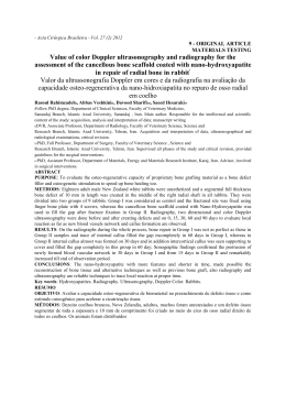
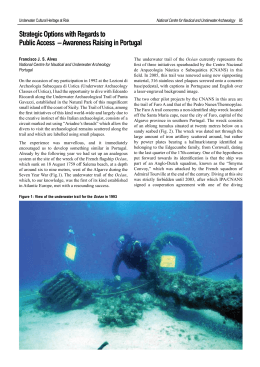
Figure 1 shows a ray trace drawing of an acoustic underwater propagation. Starting from the
left the source transmits an impulse
that will reach the hydrophone by a number of
paths (with different delays) which includes watercolumn refracted, bottom and surface
reflected paths. The watercolumn refracted paths are due to the sound speed profile C(z,r)
which is a function of depth and range. Due to number of paths, it results a complex IR
structure composed of paths with different delays and due to the channel environmental
properties variation each path is affected by a different amount of Doppler.
Figure 1. Underwater Environment with source transmitting impulses which reach the hydrophone array
through different paths
Doppler distortion is usually analysed as a compression/expansion of the received signal.
However it was shown that it can be analysed at the path level since [5]
where
is a single path, , propagating between the source and the hydrophone, ,
transmitted at an instant
and received at the hydrophone after a delay . Due to the
channel properties variability the length,
of the path changes with a velocity
. The ratio between such velocity and the sound speed, , induces a delay variation
in the
argument and a frequency shift given in (1) by the complex exponential. Such
frequency shift is responsible for the Doppler spread that also depends on the central
frequency, , of the narrowband transmitted signal.
Equation (1) represents a time variable IR for a single path which can be easily generalized to
p paths by
where
incorporates all the Doppler experienced by the
due to all arriving paths.
Instituto de Estudos do Mar Almirante Paulo Moreira
hydrophone of the array
IX Encontro de tecnologia em Acústica Submarina – IX ETAS
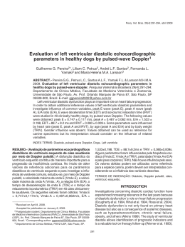
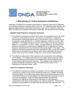
Figure 2 shows an example where a surface suspended array receives a signal transmitted by
a fixed source. For clarity only the direct path and a surface reflected path between the source
and the hydrophone are shown. Considering that the only environmental variability is due to
the surface motion it results that there will be a Doppler induced in both paths. In fact, the
direct path , will be affected by the up-down and range movement of the surface suspended
array that will result in a velocity, , of the path , . The surface reflected path , is
affected by the array motion and by the surface motion at the location where the surface
reflection occurs resulting in a velocity , , for path , . As it was mentioned before such
velocities are a function of the paths length variability and their sign is positive when the path
enlarges and negative if the path become shorter. When a signal is transmitted in such
channel the largeness / shortness of the path makes a corresponding expansion / compression
of the received signal that is given by [6]
where
is the expansion/compression factor given by
Putting the value of
from (4) in (3) it results
that relates the velocity with the corresponding Doppler spread
.
Figure 2.Two arrivals from transmitter to the receiver and their velocity projections
III.
EXPERIMENT DESCRIPTION
The data for analysis was collected during the CALCOMM’10 experiment, which took place
off the south coast of Portugal, about 12 nautical miles south east of Vilamoura, from 22nd to
24th of June 2010. The main objectives of the experiment are to collect field calibration data
for tomography purposes and transmit communication signals in different frequency bands to
analyse the performance of underwater communication systems.
Instituto de Estudos do Mar Almirante Paulo Moreira
IX Encontro de tecnologia em Acústica Submarina – IX ETAS
The acquisition system used for gathering the data comprises two acoustic oceanographic
buoys (AOBs), one with 8 hydrophones and the other with 16 hydrophones. There are two
sources of transmission for low and high frequency named AERU and PASU respectively
[7].
The data presented in this paper was taken on Day 2 of the experiment from the 16
hydrophone array in which all the hydrophones are equally spaced at 4 m. We will be
focussing mainly on the communication signals transmitted during the experiment. Some
details about the different transmitted signals during the experiment are shown in table 1.
Code
Type
Duration
(sec)
Baud
Rate
(bps)
Start-stop
freq.
(kHz)
LF_AERU1
MF_AERU1
MF_PASU1
HF_PASU1
LF_AERU2
MF_AERU2
MF_PASU2
HF_PASU2
LFM
LFM
LFM
LFM
QPSK
QPSK
QPSK
QPSK
0.1
0.1
0.1
0.1
30.2
30.2
30.2
30.2
500
1000
1000
2000
2.64-3.75
5.0-7.0
5.0-7.0
10-15
2.9-3.5
5.5-7.0
5.5-7.0
11.0-14.0
Silence Sampling
at the
Frequeend
ncy
(sec)
0.2
50000
0.2
50000
0.2
44100
0.2
44100
0.2
50000
0.2
50000
0.2
44100
0.2
44100
Table 1. Signal Specification for the CALCOMM'10 Experiment
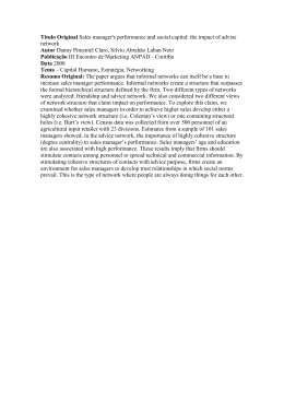
Figure 3a) shows a down refracting sound speed profile measured during the experiment.
Figure 3b) shows the source and receiver locations during data transmissions plotted over the
bathymetric map of the area where the experiment took place. During the data transmission
analysed in this paper the source array distance was around 850 m with a downslope
bathymetry, the source was located at about 12 m depth and the first hydrophone of the array
was located 6.3 m from the surface.
(a)
(b)
Figure 3: (a) Down reflecting sound speed profile during Day 2; (b) Day 2 bathymetry map of the work
area with GPS estimated locations of AOB21 (A1d) and AOB22 (A2d) deployments and their recovery
(A1r,A2r), ship/source track (dotted line) and ship track during field calibration events (green lines).
Instituto de Estudos do Mar Almirante Paulo Moreira
IX Encontro de tecnologia em Acústica Submarina – IX ETAS
IV.
DATA PROCESSING AND RESULTS
This paper address the low frequency chirps (LF-AERU1 code, see table 1) with the central
frequency band of 2.64 to 3.75 kHz, a duration of 0.1 sec and a repetition rate of 0.3 sec.
during 15 sec. The received chirps were first passed through a band pass filter to remove the
out of band noise, then the filtered signal was converted to baseband and finally the baseband
signal was pulse compressed with the transmitted chirps to get the channel IR estimate.
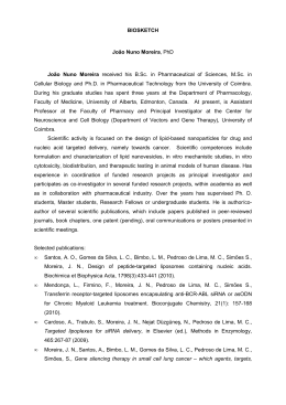
Figure 4 (a) shows the estimated arriving pattern that comprises all the IR estimates along the
array of hydrophones and (b) along the 15 seconds of transmissions for channel 3.
(a)
(b)
4
x 10
10
2
2
20
30
40
1
50
0.5
Time (sec)
1.5
Depth (m)
10000
4
8000
6
6000
8
10
4000
12
2000
60
14
0.11
0.12
0.13
0.14
Time (sec)
0.15
0.16
0.17
0.02 0.04 0.06 0.08 0.1
Delay (sec)
0.12 0.14 0.16
Figure 4: Impulse response estimates: (a) for 16 Hydrophone array and white lines showing the selected
arrival; (b) for channel 3 along the 15 seconds
The arriving pattern (see figure 4a) presents a first arrival followed by a second arrival with
much higher power. Observing the second wavefront, (with a stronger power) it is clear that
the signal arrives first to the bottom hydrophone and at last to the top hydrophone, since the
source is placed close to the surface (at 12 m depth) this reveals that this wave front should be
due the bottom reflecting paths. The first wavefront, with a smaller power than the second,
arrives first to the top hydrophone and at least to the bottom hydrophones suggesting that it
should travel in the top down direction which is only possible for the direct path and/or for
the surface reflecting path. Simulations with the Bellhop acoustic propagation model [8]
reveals that in such environment the first wavefront is due to a destructive interference of the
direct and surface reflecting wavefronts, that arrives to the array simultaneously, with the
same delay but with opposite phases [9]. The main objective of this paper is to identify the
presence of those two paths (direct and surface reflected) in the first wavefront without using
an acoustic propagation model but rather using a Doppler based method.
The proposed method assumes that each of the paths is affected by different dynamics of the
environment: the direct path is affected by the source and hydrophone motion while the
surface reflected path is also directly affected by the surface waves motion (see figure 2) at
the location where the surface reflection occurs. In order to identify the presence of those two
paths in the first arrival we start by isolating the first visible arrival applying a window as it
can be seen in figure 4a. After selecting the third hydrophone we have analysed the behaviour
Instituto de Estudos do Mar Almirante Paulo Moreira
IX Encontro de tecnologia em Acústica Submarina – IX ETAS
of the first arrival in time and Doppler for the IR estimates obtained by pulse compressing 50
chirps transmitted during 15 sec (see Figure 4b). Figure 5a shows the variability of the
selected path with time. Figure 5b shows the corresponding Doppler spread where it can be
observed that there are: (i) a main spot of Doppler at approximately 0.01Hz, and (ii) two side
spots at 0.16Hz and -0.1Hz. Those observations reveal that in the channel there are more than
one path. The main spot at 0.01Hz should correspond to a main path while the side spots can
correspond to two different paths or to a single path that is affected by two different Doppler
values as can be the case of a surface reflected path that when the wave goes down the length
of the path reduces and when the wave is going in the upper direction the length of the path
increases.
(a)
(b)
4
3000
2
9
-0.6
2500
8
4
-0.4
2000
6
1500
8
1000
10
12
500
14
Doppler (Hz)
Time (sec)
x 10
10
-0.8
7
-0.2
6
0
5
0.2
4
0.4
3
0.6
2
1
0.8
0.046
0.047
0.048
0.049
0.05
Delay (sec)
0.051
0.052
0.053
0.05
0.1
0.15
0.2
0.25
0.3
Delay (sec)
0.35
0.4
0.45
Figure 5. Doppler Spectrum for the selected arrival for 15 seconds
However if the side spots are due to a single surface reflecting path the two side spots should
not be visible simultaneously in a short time slot since the up and down movement of the
surface wave occurs at different times. Applying a time window of 4 sec to figure 5a the
corresponding Doppler spread was computed.
(a)
(b)
Figure 6. (a) Doppler computed only for 4 sec time window where we can see two Dopplers i) due to one
main arrival at -0.01Hz and ii) due to a surface reflected arrival at approximately 0.5 Hz (b) Doppler
summation over the delay axis
Instituto de Estudos do Mar Almirante Paulo Moreira
IX Encontro de tecnologia em Acústica Submarina – IX ETAS
(b)
(a)
Figure 7. (a) Doppler computed only for 4 sec time window where we can see three Dopplers i) due to one
main arrival at 0.1 Hz and ii) due to a top reflected arrival at ~ -0.4 Hz and at ~0.5 Hz, (b) Doppler
summation over the delay axis
(a)
(b)
Figure 8. (a) Doppler computed only for 4 sec time window where we can see two Dopplers i) due to one
main arrival at 0.1 Hz and ii) due to a top reflected arrival at ~ -0.4 Hz, (b) Doppler summation over the
delay axis
Figure 6, 7, 8 (a) show the Doppler spread computed with a window of 4 where the window
slides 0.5 sec from 6 to 7 and then 8. Figure 6, 7, 8 (b) show the corresponding Doppler
spread summation along the delay axis. These figures allow for the following observations:
(i) figure 6 (a) shows a main spot at -0.01 Hz and a relevant side spot at ~0.5Hz; (ii) figure 7
(a) shows a main spot at 0.1Hz and two side spots at approximately -0.4Hz and 0.5Hz; and
(iii) figure 8 (a) shows a main spot at 0.1Hz and a side spot at 0.4Hz. In all cases the main
spot is due to the direct path ( in figure 2) that due to the array motion presents different
Doppler values for the 3 different windows nevertheless with values around zero. The side
spots are due to surface motion that makes the surface reflected path ( in figure 2) larger
and shorter, in the following manner: in case (i) the Doppler value is positive revealing that
for that window the surface wave is moving up and the path is becoming larger; in case (iii)
the Doppler value is negative revealing that for that window the wave is moving down and
the path is becoming shorter; and for case (ii) there are two side spots one negative and the
other positive revealing that for that time window the surface wave is crossing a crest, where
before the crest the path is becomes larger and after the crest the path becomes shorter.
V.
CONCLUSION AND FUTURE WORK
In this paper a Doppler domain analysis of underwater acoustic channel time variability was
done. The Doppler analysis was applied to channel impulse response estimates obtained
during the CALCOMM’10 experiment. Isolating a single path from an IR estimate and
Instituto de Estudos do Mar Almirante Paulo Moreira
IX Encontro de tecnologia em Acústica Submarina – IX ETAS
computing its Doppler spread it was possible to identify that it comprises two paths (a direct
and a surface reflected) that at the receiver side add destructively. Moreover it was possible to
identify the environmental phenomenon that generates the time variability of the channel.
Future work will address the use of the Doppler spread function estimates in the development
of robust equalizers for underwater communications.
ACKNOWLEDGMENT
This work was partially supported by project PHITOM (PTDC/EEATEL/71263/2006),
funded by FCT, Portugal. The authors would like to thank chief scientist Dr. Paulo Felisberto
and ship crew for their support during CALCOMM’10.
REFERENCES
[1] BRAGARD, P.; JOURDAIN, G.; , "Adaptive equalization for underwater data
transmission," International Conference on Acoustics, Speech, and Signal Processing,
ICASSP-89., 1989 pp.1171-1174 vol.2, 23-26 May 1989
[2] DOHERTY, J.F.; "Decision feedback equalization of data with spectral nulls," Military
Communications Conference, 1990. MILCOM '90, Conference Record, A New Era. 1990
IEEE , vol., no., pp.76-80 vol.1, 30 Sep-3 Oct 1990
[3] RODERICK, W.I.; DEAVENPORT, R.L.; , "Doppler characteristics of sea surface
reflected and scattered acoustic signals induced by surface wave motion," OCEANS '93.
Engineering in Harmony with Ocean. Proceedings , vol., no., pp.I287-I292 vol.1, 18-21 Oct
1993.
[4] DHANOA, J.S.; ORMONDROYD, R.F.; HUGHES, E.J.; "An improved digital
communication system for doubly-spread underwater acoustic channels using evolutionary
algorithms," OCEANS 2003. Proceedings , vol.1, no., pp.109-114 Vol.1, 2003.
[5] SILVA. A.; RODRIGUEZ O.; ZABEL F.; HUILERY J.; JESUS S. M. “Underwater
acoustics simulations with time variable acoustics propagation model”, Proceeding of 10th
European Conference on Underwater Acoustics, vol. 2, pp. 989-996, 2010.
[6] GOMES J.; SILVA J.; JESUS S. M, “Adaptive spatial combining for passive timereversed communications”, J. Acoust. Soc. Am. 124, 1038 (2008),
[7] SILVA A.; ZABEL F.; MARTINS C., ``Acoustic Oceanographic Buoy: a telemetry
system that meets rapid environmental assessment requirements'', Sea Technology, Vol. 47,
No.9, pp.15 - 20, September 2006.
[8] PORTER M. B.; LIU Y. C. “Finite-Element Ray Tracing”. Theoretical and
Computational Acoustics, Vol. 2, World Scientific Publishing Co., 1994.
[9] FELISBERTO, P.; JESUS,S.;MARTINS,N. "Field Calibration a Tool for Acoustic Noise
Prediction: The CALCOM'10 data set", IX Encontro de Tecnologia Acustica Submarina IX ETAS, Arraial do Cabo (Brasil), November.
Instituto de Estudos do Mar Almirante Paulo Moreira
Download