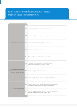
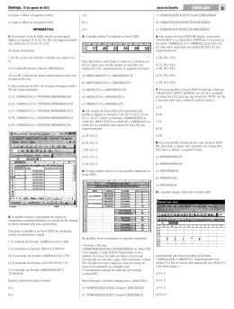
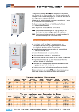
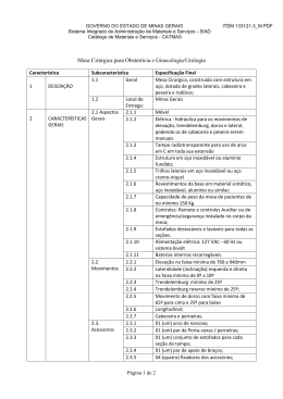
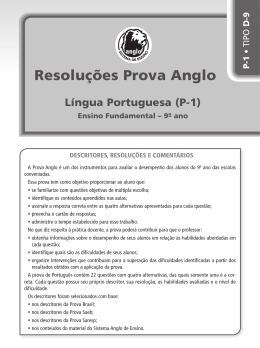
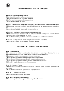
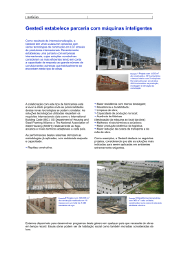
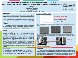
BOMBAS
MULTICELULARES
Multistage Pumps
Séries I Series
BMH/BMHT
BMV/BMVT
Horizontais e verticais
Horizontal and vertical
Todas as informações e especificações incluídas neste catálogo
podem ser alteradas pela EFAFLU sem aviso prévio.
Este catálogo inclui apenas alguns produtos mais correntes da
gama EFAFLU. Para outros produtos contacte os nossos Serviços
Técnicos comerciais na Póvoa de Varzim - [email protected],
Lisboa - [email protected] ou Exportação - [email protected]
All the information and specifications included in this catalogue
can be modified by EFAFLU without prior notice.
This catalogue lists only some of the more common products of
EFAFLU. For other products please contact our sales & technical
department in Póvoa de Varzim - [email protected],
Lisbon - [email protected] or Export - [email protected]
ÍNDICE
Características técnicas
04
Aplicações
Condições operacionais
Caracterização das bombas
Motor elétrico
Gama geral de desempenho
Ligações nas bombas
Definição dos modelos
Construção
05
06
Performance curves, Weights and Dimensions
07
08
10
INFORMAÇÕES GERAIS - BMV(T)
Definição dos modelos
Pressão máxima
NPSH e operação em paralelo
12
13
14
15
16
17
18
19
20
Performance
Product range
Construction
Pump sectional drawing and materials
BMV(T) 2; 3; 4
BMV(T) 8; 12; 16; 20
BMV(T) 32; 42; 65; 85
BMV(T) 120; 150; 200
Definition of models
Maximum pressure
NPSH and operation in parallel
Minimum suction pressure NPSH
NPSH and performance in parallel
21
INFORMAÇÕES TÉCNICAS - BMV(T)
Curve illustration
TECHNICAL DATA - BMV(T)
Curvas de desempenho, Peso e Dimensões
BMV(T) 2, 3
BMV(T) 4, 8
BMV(T) 12, 16
BMV(T) 20, 32
BMV(T) 42, 65
BMV(T) 85, 120
BMV(T) 150, 200
Technical features
Applications
Operating conditions
Pumps
Electric motor
Pressão mínima de aspiração NPSH
NPSH e operação em paralelo
Interpretação das curvas de desempenho
BMH(T) 2
BMH(T) 4, 8
BMH(T) 12, 16
GENERAL DATA - BMV(T)
Aplicações
Condições operacionais
Caracterização das bombas
Motor elétrico
Desenho da bomba em corte e materiais
BMV(T) 2; 3; 4
BMV(T) 8; 12; 16; 20
BMV(T) 32; 42; 65; 85
BMV(T) 120; 150; 200
Performance
Pump connections
Definition of models
Construction
TECHNICAL DATA - BMH(T)
Curvas de desempenho, Peso e Dimensões
Gama geral de desempenho
Gama de produto
Construção
Technical features
Pump sectional drawing and materials
INFORMAÇÕES TÉCNICAS - BMH(T)
Características técnicas
GENERAL DATA - BMH(T)
Applications
Operating conditions
Pumps characterization
Electric motor
Desenho da bomba em corte e materiais
BMH(T) 2
BMH(T) 4, 8
BMH(T) 12, 16
I N D E X
INFORMAÇÕES GERAIS - BMH(T)
página
page
Performance curves, Weights and Dimensions
22
24
26
28
30
32
34
BMV(T) 2, 3
BMV(T) 4, 8
BMV(T) 12, 16
BMV(T) 20, 32
BMV(T) 42, 65
BMV(T) 85, 120
BMV(T) 150, 200
www.efaflu.pt < 03
INFORMAÇÕES GERAIS I GENERAL DATA BMH(T)
BMH(T)
CARACTERÍSTICAS TÉCNICAS I Technical Features
Aplicações I Applications
As bombas do tipo BMH são usadas principalmente no campo industrial:
BMH pumps are mainly used in industrial area:
Sistemas de ar-condicionado
Air-conditioning system
Sistema de arrefecimento
Cooling system
Limpeza industrial
Industrial cleaning
Tratamento de Água (purificação de Água)
Water treatment (Water purification)
Aquacultura
Aquiculture
Fertilizantes /sistema de medição
Fertilizing/measurement system
Aplicações ambientais
Environment applications
Outras aplicações especiais
Other special applications
Condições operacionais I Operating conditions
Temperatura do líquido:
Temperatura normal: -150C~+700C
Água quente: +700C~+1100C (opcional)
Temperatura ambiente: até +400C
Pressão máx. de operação: 10 bar
Pressão máx. na admissão é limitada pela pressão máx. da operação
Liquid temperature:
Normal temperature: -150C~+700C
Hot water: +700C~+1100C (optional)
Room temperature: up to +400C
Max. operation pressure: 10 bar
Max. inlet pressure is limited by max. operation pressure
Caracterização das bombas I Pump’s characterization
As bombas BMH são do tipo centrífugo, multicelulares, horizontais, não
auto-ferrantes, acopladas a motor elétrico por veio longo.
A estrutura compacta torna a bomba de pequenas dimensões com aspiração axial e descarga radial.
The BMH type is an horizontal multistage, non-self priming, centrifugal
pump, coupled to a long shaft electric motor.
The compact structure turns the pump small sized with axial suction and
radial discharge.
Motor elétrico I Electric motor
Motor TEFC 2 pólos
TEFC 2-poles motor
Classe de proteção: IP55
Protection class: IP55
Classe de isolamento: F
Insulation class: F
Tensão standard, 50 Hz: 1 x 220 - 240 V
3 x 220 - 240 V/380 - 415 V
Standard frequency, 50 Hz: 1 x 220 - 240 V
3 x 220 - 240 V/ 380 - 415 V
Motor monofásico (máx): 2.4 kW
Single-phase motor (max.): 2.4 kW
04 > Bombas Multicelulares I Multistage Pumps
INFORMAÇÕES GERAIS I GENERAL DATA BMH(T)
BMH(T)
GAMA GERAL DE DESEMPENHO I Performance
BMH(T)
50Hz
60
50
40
BMH(T) 16
BMH(T) 12
20
BMH(T) 8
BMH(T) 2
BMH(T) 4
30
15
10
1
2
4
6
8
10
16
20
30
LIGAÇÕES NAS BOMBAS I PUMP CONNECTIONS
Ligações nas Bombas
Pump connections
BMH(T)
2
BMH(T)
4
BMH(T)
8
BMH(T)
12
BMH(T)
16
Entrada I Inlet
G1
G1 1/4
G1 1/2
G1 1/2
G2
Saída I Outlet
G1
G1
G1 1/4
G1 1/2
G2
DEFINIÇÃO DOS MODELOS I DEFINITION OF MODEL
Caudal nominal m3/h
Rated flow m3/h
Estágios x 10
Stages x 10
BMH T 8 - 20
Bomba multicelular horizontal
Horizontal multistage pump
Só aplicável quando todos os componentes em
contacto com líquido são em aço inoxidável AISI
304.*
Only applicable when all components in contact
with the liquid are in stainless steel AISI 304.*
www.efaflu.pt < 05
INFORMAÇÕES GERAIS I GENERAL DATA BMH(T)
BMH(T)
CONSTRUÇÃO I CONSTRUCTION
Desenho da bomba em corte I Pump Sectional drawing
BMH(T) / 50Hz
Materiais I Materials
COMPONENTE I COMPONENT
MATERIAL I MATERIAL
AISI/ASTM
AISI304
2
Difusor de descarga I Discharge diffuser
Aço inoxidável I Stainless steel
3
Rolamento I Bearing
Carboneto de tungsténio I Tungsten carbide
4
Impulsor I Impeller
Aço inoxidável I Stainless steel
AISI304
5
Veio I Shaft
Aço inoxidável I Stainless steel
AISI304
6
Descarga I Discharge diffuser
Aço inoxidável I Stainless steel
AISI304
8
Empanque mecânico I Mechanical seal
9
Tampo do veio do motor I Shaft cover of motor
Alumínio I Aluminum alloy
10
Base I Base plate
Ferro Fundido I Cast iron
ASTM25B
11
Tirante I Pull-rod
Aço inoxidável I Stainless steel
AISI304
12
Difusor I Diffuser
Aço inoxidável I Stainless steel
AISI304
13
Suporte do elemento difusor I Support diffuser
Aço inoxidável I Stainless steel
AISI304
14
Casquilho do impulsor I Impeller bushing
Aço inoxidável I Stainless steel
AISI304
1
Aspiração I Suction
Ferro Fundido I Cast iron
ASTM25B
7
Descarga I Discharge
Ferro Fundido I Cast iron
ASTM25B
BMH
BMHT
1
Aspiração I Suction
Aço inoxidável I Stainless steel
AISI304
7
Descarga I Discharge
Aço inoxidável I Stainless steel
AISI304
06 > Bombas Multicelulares I Multistage Pumps
INFORMAÇÕES TÉCNICAS I TECHNICAL DATA BMH(T)
BMH(T) 2
BMH(T) 2
50Hz
60
50
40
30
20
10
0
MODELO
MODEL
kW
L1
L2
L3
D
H
K
PESO
WEIGHT
(Kg)
DIMENSÕES I DIMENSIONS (mm)
BMH(T) 2-20
0.37
305
87
84
145
215/230
96
15
BMH(T) 2-30
0.55
323
105
102
145
215/230
96
15
BMH(T) 2-40
0.55
341
123
120
145
215/230
96
15
BMH(T) 2-50
0.55
359
141
138
145
215/230
96
15
BMH(T) 2-60
0.75
422
159
156
170
215/245
100
17
www.efaflu.pt < 07
INFORMAÇÕES TÉCNICAS I TECHNICAL DATA BMH(T)
BMH(T) 4
BMH(T) 4
50Hz
MODELO
MODEL
08 > Bombas Multicelulares I Multistage Pumps
kW
L1
L2
L3
D
H
K
PESO
WEIGHT
(Kg)
DIMENSÕES I DIMENSIONS (mm)
BMH(T) 4-20
0.55
329
105
102
145
215 / 230
96
15
BMH(T) 4-30
0.55
356
132
129
145
215 / 230
96
15
BMH(T) 4-40
0.75
416
162
156
170
225/ 245
100
17
BMH(T) 4-50
1.1
455
188
183
170
225/ 245
100
17
BMH(T) 4-60
1.1
482
213
210
170
225/ 245
100
17
INFORMAÇÕES TÉCNICAS I TECHNICAL DATA BMH(T)
BMH(T) 8
BMH(T) 8
50Hz
MODELO
MODEL
kW
L1
L2
L3
D
H
K
PESO
WEIGHT
(Kg)
DIMENSÕES I DIMENSIONS (mm)
BMH(T) 8-10
0.75
395
126
108
170
230/265
100
20
BMH(T) 8-20
0.75
395
126
108
170
230/265
100
20
BMH(T) 8-30
1.1
425
156
138
170
230/265
100
25
BMH(T) 8-40
1.5
490
186
168
180
240/270
100
28
BMH(T) 8-50
2.2
520
216
198
180
240/270
100
30
www.efaflu.pt < 09
INFORMAÇÕES TÉCNICAS I TECHNICAL DATA BMH(T)
BMH(T) 12
H
[m]
BMH(T) 12
50Hz
60
50
40
30
20
10
0
0
1
0.0
2
3
0.5
4
5
6
1.0
7
1.5
8
2.0
9
10
2.5
11
12
3.0
13
14
3.5
4.0
2.4
1.8
1.2
0.6
0.0
0
1
2
3
4
5
6
7
8
9
10
11
12
13
14
0
1
2
3
4
5
6
7
8
9
10
11
12
13
14
6
4
2
0
G112
MODELO
MODEL
E
N
K
PESO
WEIGHT
(Kg)
108 230 / 265 170
228
118
100
20
126
108 230 / 265 170
228
118
100
21
460
156
138 240 / 270 180
228
118
100
25
2.4
490
186
168 240 / 270 180
228
118
100
29
3
555
216
198
240
126
100
34
L1
L2
L3
BMH(T) 12-10 0.75 395
126
BMH(T) 12-20
1.2
395
BMH(T) 12-30
1.8
BMH(T) 12-40
BMH(T) 12-50
G112
10 > Bombas Multicelulares I Multistage Pumps
DIMENSÕES I DIMENSIONS (mm)
kW
H
270
D
195
INFORMAÇÕES TÉCNICAS I TECHNICAL DATA BMH(T)
BMH(T) 16
BMH(T) 16
50Hz
MODELO
MODEL
kW
DIMENSÕES I DIMENSIONS (mm)
L1 L2 L3
H
D
E
N
A
M
B
J
d
PESO
WEIGHT
K
(Kg)
BMH(T) 16-10
1.1
423 151 126 230/265 180 227 117 130 108 160 138 9 100
17.5
BMH(T) 16-20
2.2
455 151 126 240/270 180 228 118 130 108 160 138 9 100
27
BMH(T) 16-30
3
561 196 171
270
195 240 130 130 108 160 138 9 100
33
BMH(T) 16-40
4
621 340 216
270
220 230 120 230 190 170 140 12 100
41
www.efaflu.pt < 11
INFORMAÇÕES GERAIS I GENERAL DATA BMV(T)
BMV(T)
CARACTERÍSTICAS TÉCNICAS I TECHNICAL FEATURES
Aplicações I Applications
As bombas BMV e BMVT são utilizáveis numa ampla gama de aplicações
hidráulicas. Podem ser utilizadas na bombagem de água para consumo
público assim como para bombagem de fluidos industriais com diferentes temperaturas, caudais e pressões. A gama de bombas BMV é aplicável na bombagem de líquidos não corrosivos, enquanto a gama BMVT é
adequada para líquidos moderadamente corrosivos. Os principais campos de aplicação são:
Abastecimento de água: Bombagem de água potável e pressurização
em sistemas públicos de distribuição de água, bombagem em condutas principais e em edifícios altos.
Pressurização industrial: Sistemas de processamento de água, de
limpeza, de lavagem a alta pressão, de combate a incêndio.
Trasfega de fluidos: Sistemas fechados de refrigeração e de ar condicionado, enchimento de caldeiras e bombagem de condensados,
trasfega de ácidos e bases.
Tratamento de água: Sistemas de ultra filtração, osmose inversa, destilação, recirculação de água em tanques e piscinas.
BMV and BMVT pumps are used on a large range of hydraulic applications. They can be used in pumping water for public consumption as well
as for pumping of industrial fluids with different temperatures, flow rates
and pressures. The range of BMV pumps is applicable in non-corrosive
liquid pumping, while BMVT range is suitable for moderately corrosive
fluids. The main fields of application are:
Water supply: Pumping potable water and pressurization in public
systems of water distribution, pumping mains and high buildings.
Industrial boosting: Process flow water systems, cleaning systems,
high-pressure washing systems, fire fighting systems.
Liquid racking: Closed cooling and air-conditioning systems, fulfilling
boilers and condensate pumping, acids and bases.
Water treatment: Ultra filtration systems, reverse osmosis, distillation,
recirculation of water in tanks and swimming pools.
Irrigation: General irrigation, sprinkler, dripping.
Rega: Rega em geral, por aspersão, por gotejamento
Condições operacionais I Operating conditions
Fluidos no estado líquido, limpos, não inflamáveis e não explosivos,
isentos de sólidos.
Fluid in the liquid state, clean, non-flammable and non-explosive,
solids-free.
Temperaturas permitidas do líquido:
Versão normal: -150C ~ +700C
Versão para água quente: até ~ +1200C (opcional)
Allowed temperatures in the liquid:
Normal version: -150C to ~ +700C
Hot water version: up to ~ +1200C (optional)
Temperatura ambiente: até +400C
Room temperature: up to +400C
Altitude: até 1000m
Height: up to 1000m
Caracterização das bombas I Pumps characterization
As bombas BMV e BMVT são do tipo centrífugo, multicelular, vertical,
não auto-ferrantes, acionadas por motores elétricos normalizados. O
acoplamento motor à bomba é feito através dos veios por uma união
de acoplamento rígida. A camisa exterior da bomba e os componentes
através dos quais circula o fluido são fixos rigidamente entre o suporte
adaptador superior, e o corpo inferior da bomba, através das guias de
fixação. As ligações de entrada e saída da bomba estão montadas em
linha e encontram-se localizadas no corpo de aspiração e descarga da
bomba. Recomenda-se que este tipo de bomba seja equipado com sistemas contra a falta de água, ausência de fase e sobrecargas.
The BMV and BMVT pumps are centrifugal, multistage, vertical, not selfpriming type, driven by standard electric motors. The motor coupling to
pump is done through the pump shaft by a rigid union coupling. The external jacket of the pump and components through which the fluid flows
are fixed rigidly between the upper adapter bracket and the lower body
of the pump, through the mounting tabs. The inlet and outlet connections of the pump are mounted in line and are located in the body of
suction and discharge of the pump. It is recommended that this type of
pump is equipped with systems from water shortages, lack of phase and
overloads.
Motor elétrico I Electric motor
Motor normalizado blindado de dois pólos (2900 rpm)
Full-enclosed air-blast two-pole standard motor (2900 rpm)
Classe de proteção: IP55
Protection class: IP55
Classe de isolamento: F
Insulation class: F
Frequência: 50 Hz
Frequency: 50 Hz
Tensão: monofásica 1x230 V ou trifásica 3x400 V
Voltage: single-phase 1x230 V or three-phase 3x400 V
12 > Bombas Multicelulares I Multistage Pumps
INFORMAÇÕES GERAIS I GENERAL DATA BMV(T)
BMV(T)
GAMA GERAL DE DESEMPENHO I Performance
H
[m]
300
BMV(T)
50Hz
200
120
100
BMV(T) 150
BMV(T) 200
BMV(T) 120
BMV(T) 85
BMV(T) 65
BMV(T) 42
BMV(T) 32
BMV(T) 20
BMV(T) 16
BMV(T) 12
40
BMV(T) 4
BMV(T) 2
BMV(T) 3
60
BMV(T) 8
80
20
10
0.8 1 1.2 1.6 2
2.8
4
5
6
8 10 12 1416 20 25 30
40 50 60 70 80
110 140 180 240 Q [m3/h]
BMV(T)
GAMA DE PRODUTO I PRODUCT RANGE
DESCRIÇÃO I DESCRIPTION
Caudal nominal I Rated flow (m3/h)
BMV(T) BMV(T) BMV(T) BMV(T) BMV(T) BMV(T) BMV(T) BMV(T) BMV(T) BMV(T) BMV(T) BMV(T)
2
3
4
8
12
16
20
32
42
65
85
120
2
3
4
8
12
16
20
32
42
65
85
120
BMV(T)
150
BMV(T)
200
150
200
Caudal nominal I Rated flow (l/s)
0.56
0.83
1.1
2.2
3.3
4.4
5.6
8.9
11.7
18
24
33
41.6
55.6
Gama de caudais I Flow range (m3/h)
1-3.5
1.2-4
1.5-7
5-12
7-16
8-22
10-28
16-40
25-55
30-80
50-110
60-150
80-180
100-240
1.9-4.4
2.2-6.1
2.8-7.8
22-50
27.8-66.7
Gama de caudais I Flow range (l/s)
Pressão máxima
Maximum pressure (bar)
Potência dos motores I Motor power (kW)
0.28-0.97 0.33-1.1 0.42-1.9 1.4-3.3
23
22
21
21
22
22
23
26
30
22
17
16
16
16
0.37-3
0.37-3
0.37-4
0.75-7.5
1.5-11
2.2-15
1.1-18.5
1.5-30
3.0-45
4.0-45
5.5-45
11-75
11-75
18.5-110
Gama de temperaturas do líquido
Liquid temperature range (0C)
Máxima eficiência I Max. efficiency (%)
4.4-11.1 6.9-15.3 8.3-22.2 13.8-30.5 16.7-41.7
-15 ~+120 ( detalhes na página 12 I details on page 12 )
46
54
57
62
63
66
69
73
75
76
77
74
73
79
TIPO I TYPE
BMV
a
BMVT
a
a
a
a
a
a
a
a
a
a
a
a
a
a
a
a
a
a
a
a
a
a
a
a
a
a
a
DN125
DN125
DN150
-
-
-
ligações nas bombas I PIPE CONNECTIONS bmv
Flange DIN I DIN Flange
Flange oval I Oval Flange
DN25
G1
DN25
DN32
DN40
DN50
DN50
DN50
DN65
DN80
G1
G11/4
G11/2
-
-
-
-
-
DN100 DN100
-
-
ligações nas bombas I PIPE CONNECTIONS bmvt
Flange DIN I DIN Flange
DN25
DN25
DN32
DN40
DN50
DN50
DN50
DN65
DN80
DN125
DN125
DN150
Vitaulica I Cutting ferrule joint
DN32
DN32
DN32
DN50
DN50
DN50
DN50
-
-
DN100 DN100
-
-
-
-
-
Roscada I Pipe thread
ZG11/4
ZG11/4
ZG11/4
ZG2
ZG2
ZG2
ZG2
-
-
-
-
-
-
-
www.efaflu.pt < 13
INFORMAÇÕES GERAIS I GENERAL DATA BMV(T)
CONSTRUÇÃO I CONSTRUCTION
BMV(T) 2; 3; 4
Desenho da bomba em corte I Pump Sectional drawing
Materiais I Materials
COMPONENTE I COMPONENT
1
Motor elétrico I Electric motor
2
Suporte adaptador I Adaptor bracket
4
Empanque mecânico I Mechanical seal
5
Elemento difusor de descarga I Top diffuser
MATERIAL I MATERIAL
AISI/ASTM
Ferro fundido I Cast iron
ASTM25B
Aço inoxidável I Stainless steel
AISI304
6
Elemento difusor I Diffuser
Aço inoxidável I Stainless steel
AISI304
7
Suporte do elemento difusor I Support diffuser
Aço inoxidável I Stainless steel
AISI304
AISI304
8
Elemento guia I Inducer
Aço inoxidável I Stainless steel
11
Chumaceira I Bearing bracket
Carboneto de tungsténio I Tungston carbide
12
Impulsor I Impeller
Aço inoxidável I Stainless steel
AISI304
13
Veio I Shaft
Aço inoxidável I Stainless steel
AISI304
14
Espaçador I Spacer
Aço inoxidável I Stainless steel
AISI304
15
Camisa I Sleeve
Aço inoxidável I Stainless steel
AISI304
16
União de acoplamento I Coupling
Aço carbono I Carbon steel
BMV
9
Corpo de aspiração e descarga I Suction and
discharge body
Ferro fundido I Cast iron
ASTM25B
BMVT
14 > Bombas Multicelulares I Multistage Pumps
3
Tampa do corpo I Body cover
Aço inoxidável I Stainless steel
AISI304
9
Corpo de aspiração e descarga I Suction and
discharge body
Aço inoxidável I Stainless steel
AISI304
10
Base I Base plate
Ferro fundido I Cast iron
ASTM25B
INFORMAÇÕES GERAIS I GENERAL DATA BMV(T)
CONSTRUÇÃO I CONSTRUCTION
BMV(T) 8; 12; 16; 20
Desenho da bomba em corte I Pump Section drawing
Materiais I Materials
COMPONENTE I COMPONENT
1
Motor elétrico I Electric motor
2
Suporte adaptador I Adaptor bracket
4
Empanque mecânico I Mechanical seal
5
Elemento difusor de descarga I Top diffuser
MATERIAL I MATERIAL
AISI/ASTM
Ferro fundido I Cast iron
ASTM25B
Aço inoxidável I Stainless steel
AISI304
6
Elemento difusor I Diffuser
Aço inoxidável I Stainless steel
AISI304
7
Suporte do elemento difusor I Support diffuser
Aço inoxidável I Stainless steel
AISI304
AISI304
8
Elemento guia I Inducer
Aço inoxidável I Stainless steel
11
Chumaceira I Bearing bracket
Carboneto de tungsténio I Tungston carbide
12
Impulsor I Impeller
Aço inoxidável I Stainless steel
AISI304
13
Veio I Shaft
Aço inoxidável I Stainless steel
AISI304
14
Espaçador I Spacer
Aço inoxidável I Stainless steel
AISI304
15
Camisa I Sleeve
Aço inoxidável I Stainless steel
AISI304
16
União de acoplamento I Coupling
Aço carbono I Carbon steel
BMV
9
Corpo de aspiração e descarga I Suction and
discharge body
3
Tampa do corpo I Body cover
Aço inoxidável I Stainless steel
AISI304
9
Corpo de aspiração e descarga I Suction and
discharge body
Aço inoxidável I Stainless steel
AISI304
10
Base I Base plate
Ferro fundido I Cast iron
ASTM25B
Ferro fundido I Cast iron
ASTM25B
BMVT
www.efaflu.pt < 15
INFORMAÇÕES GERAIS I GENERAL DATA BMV(T)
BMV(T) 32;42;65;85
CONSTRUÇÃO I CONSTRUCTION
Desenho da bomba em corte I Pump Section drawing
Materiais I Materials
1
COMPONENTE I COMPONENT
MATERIAL I MATERIAL
AISI / ASTM
Adaptador I Lantern
Ferro fundido I Cast iron
ASTM25B
3
Empanque mecânico I Mechanical seal
4
Elemento difusor de descarga I Top diffuser
Aço inoxidável I Stainless steel
AISI304
5
Suporte do elemento difusor I Support diffuser
Aço inoxidável I Stainless steel
AISI304
6
Elemento difusor I Diffuser
Aço inoxidável I Stainless steel
AISI304
7
Elemento guia I Inducer
Aço inoxidável I Stainless steel
AISI304
9
Base I Base plate
Aço inoxidável I Stainless steel
ASTM25B
10
Chumaceira inferior I Bottom bearing bracket
Carboneto de tungsténio I Tungston carbide
11
Impulsor I Impeller
Aço inoxidável I Stainless steel
AISI304
12
Veio I Shaft
Aço inoxidável I Stainless steel
AISI316L
AISI304
AISI431
13
Camisa intermédia do veio I Intermediate bearing
Carboneto de tungsténio I Tungston carbide
14
Camisa I Sleeve
Aço inoxidável I Stainless steel
15
União de acoplamento I Coupling
Aço carbono I Carbon steel
Peças de borracha I Rubber parts
AISI304
EPDM
BMV
2
Suporte adaptador I Pump head
Ferro fundido I Cast iron
ASTM25B
8
Corpo de aspiração e descarga I Suction and
discharge body
Ferro fundido I Cast iron
ASTM25B
2
Suporte adaptador I Lantern support
Aço inoxidável I Stainless steel
AISI304
8
Corpo de aspiração e descarga I Suction and
discharge body
Aço inoxidável I Stainless steel
AISI304
BMVT
16 > Bombas Multicelulares I Multistage Pumps
INFORMAÇÕES GERAIS I GENERAL DATA BMV(T)
CONSTRUÇÃO I CONSTRUCTION
BMV(T) 120; 150; 200
Desenho da bomba em corte I Pump Section drawing
Materiais I Materials
COMPONENTE I COMPONENT
MATERIAL I MATERIAL
AISI/ASTM
1
Adaptador I Lantern
Ferro fundido I Cast iron
ASTM25B
3
Empanque mecânico I Mechanical seal
4
Descarga I Discharge
Aço inoxidável I Stainless steel
AISI304
5
Suporte do elemento difusor I Support diffuser
Aço inoxidável I Stainless steel
AISI304
6
Elemento difusor I Diffuser
Aço inoxidável I Stainless steel
AISI304
7
Elemento guia I Inducer
Aço inoxidável I Stainless steel
AISI304
9
Base I Base plate
Aço inoxidável I Stainless steel
ASTM 80-55-06
11
Impulsor I Impeller
Aço inoxidável I Stainless steel
AISI304
12
Veio I Shaft
Aço inoxidável I Stainless steel
AISI304
13
Chumaceira I Bearing bracket
Carboneto de tungsténio I Tungston carbide
14
Camisa I Sleeve
Aço inoxidável I Stainless steel
15
União de acoplamento I Coupling
Aço carbono I Carbon steel
Peças de borracha I Rubber parts
AISI304
EPDM
BMV
2
Suporte adaptador I Lantern support
Ferro fundido I Cast iron
ASTM 80-55-06
8
Corpo de aspiração e descarga I Suction and
discharge body
Ferro fundido I Cast iron
ASTM 80-55-06
BMVT
2
Suporte adaptador I Lantern support
Aço inoxidável I Stainless steel
AISI304
8
Corpo de aspiração e descarga I Suction and
discharge body
Aço inoxidável I Stainless steel
AISI304
www.efaflu.pt < 17
INFORMAÇÕES GERAIS I GENERAL DATA BMV(T)
BMV(T)
DEFINIÇÃO DOS MODELOS I DEFINITION OF MODEL
BMV/BMVT 2, 3, 4, 8, 12, 16, 20
Caudal nominal m3/h
Rated flow m3/ h
Estágios
Stages
Número de impulsores de
diâmetro reduzido
Number of small impellers
BMV T 8 - 2 / 1
Bomba multicelular vertical
Vertical multistage pump
Só aplicável quando todos os componentes em
contacto com líquido são em aço inoxidável AISI
304.*
Only applicable when all flow passage components
are of stainless steel AISI 304.*
BMV/BMVT 32, 42, 65, 85, 120, 150
Caudal nominal m3/h
Rated flow m3/ h
Estágios x 10
Stages x 10
Número de impulsores de
diâmetro reduzido
Number of small impellers
BMV T 32 - 30 - 1
Bomba multicelular vertical
Vertical multistage pump
Só aplicável quando todos os componentes em
contacto com líquido são em aço inoxidável AISI
304.*
Only applicable when all flow passage components
are of stainless steel AISI 304.*
* Sob pedido as bombas BMV podem ser integralmente fabricadas em AISI 316
Upon request BMV pumps can be completely produced in AISI 316
18 > Bombas Multicelulares I Multistage Pumps
INFORMAÇÕES GERAIS I GENERAL DATA BMV(T)
BMV(T)
DEFINIÇÃO DOS MODELOS I DEFINITION OF MODEL
BMV/BMVT 200
Caudal nominal m3/h
Rated flow m3/h
Estágios x10
Stages x10
Número de impulsores de
diâmetro reduzido A
Number of small
impellers A
BMV T 200 - 30 - 2A - B
Bomba multicelular vertical
Vertical multistage pump
Só aplicável quando todos os componentes em
contacto com líquido são em aço inoxidável AISI
304.*
Only applicable when all flow passage components
are of stainless steel AISI 304.*
Impulsor de diâmetro reduzido B
Small impeller B
PRESSÃO MÁXIMA I MAXIMUM PRESSURE
Pressão máx. de aspiração
Maximum suction pressure
As pressões máximas de aspiração são indicadas no quadro abaixo. A soma da pressão efetiva na aspiração com a pressão da bomba com a válvula fechada deve ser inferior à pressão máxima de trabalho.
The maximum suction pressures are indicated in the table below. The sum of the effective pressure in
suction with the pump pressure with closed valve must be lower than the maximum working pressure.
Pressão máx. de trabalho
Maximum working pressure
The table and chart below indicate the number of the curve from maximum pressure of working and
temperature that must be respected in each pump model.
1000
5
28
2
BMV 2, 3, 4 Flange oval I Oval flange
1
BMVT 2, 3, 4
2
BMV 8, 12, 16, 20 Flange I Flange
3
BMV 8 Flange oval I Oval flange
1
BMVT 8, 12, 16, 20
3
2250
32-10-1~32-70
1
32-80-2~32-120
4
32-130~32-140
5
BMV(T) 42
42-10-1~42-60
1
42-70-2~42-90
4
42-100-2~42-130-2
5
BMV(T) 65
3500 m
P2[%]
4
3
2
6
1
24
Nº CURVE
BMV 2, 3, 4 Flange I Flange
BMV(T) 32
O quadro e o diagrama abaixo indicam o número da curva dos limites de utilização de pressão máxima
de trabalho e de temperatura que devem ser respeitados em cada modelo de bomba.
P[bar]
Nº CURVA
MODELO
MODEL
65-10-1~65-50
1
65-60-2~65-80-1
4
BMV(T) 85
100
85-10-1~85-50-2
1
90
85-50~85-60
4
12
80
BMV(T) 120, 150, 200
6
8
70
4
60
20
16
0
-40
0
40
80
120
t[0C]
50
20
25
30
35
40
45
50
55
60
65
70
75
80 t[0C]
www.efaflu.pt < 19
INFORMAÇÕES GERAIS I GENERAL DATA BMV(T)
BMV(T)
NPSH E OPERAÇÃO EM PARALELO I NPSH AND OPERATION IN PARALLEL
Pressão mínima de aspiração NPSH I Minimum suction pressure NPSH
Para evitar que o líquido vaporize no interior da bomba, e por isso
venha a cavitar, é necessário garantir uma pressão mínima na aspiração da bomba.
To prevent the liquid to vaporize inside the pump, and so will cavitate,
it is necessary to ensure a minimum pressure in the pump suction:
H > 10,2 x Pb - NPSHr - Hf - Hv - Hs
H é a pressão absoluta na aspiração da bomba, em metros.
Pb é a pressão atmosférica absoluta, em bar.
Num sistema aberto pode ser definido 1 bar, num sistema fechado
Pb correspondente à pressão do sistema.
NPSHr “Net Positive Suction Head required” mede a capacidade de
aspiração da bomba para um determinado caudal, em metros.
Hf são as perdas de carga, elevação e atrito, na conduta de aspiração, em metros.
Hv é a pressão do vapor do líquido à temperatura de bombagem,
em metros.
Hs é a margem de segurança mínima de 0.5 metros.
H is the absolute pressure at pump suction, in meters.
Pb is the absolute atmospheric pressure, in bar.
In a open system can be defined 1 bar, in a closed system PB corresponds to the pressure of the system.
NPSHr “Net Positive Suction Head required” measures the capacity
of the pump suction for a given flow, in meters..
Hf are the load losses, elevation and friction, in the suction, in meters.
Hv is the vapor pressure of the liquid at a temperature of pumping,
in meters
Hs is the minimum safety margin of 0.5 meters.
Se H não respeitar estas condições então é imperioso aplicar uma
das soluções:
If H does not meet these conditions then it is imperative to apply
one of the solutions:
Escolher uma outra bomba com um
NPSH menor
Choosing another pump with a lower
NPSH level
Reduzir o Hf, colocando a bomba mais
próxima do líquido ou aumentando o
diâmetro da conduta de aspiração e de
todos os acessórios.
Reduce Hf, placing the pump closer to
the liquid or increasing the diameter of
the suction and all accessories.
Applying both solutions on same time
Realizar em simultâneo as duas anteriores soluções
Verifique e assegure-se que a bomba não opera em cavitação.
Verify and ensure that pump doesn´t operate in cavitation.
Operação em paralelo I Operating in parallel
A montagem de várias bombas em paralelo é mais favorável do que
uma só bomba grande:
Assembling several pumps in parallel will be an higher benefit than
a single large pump:
Aplicável a diferentes sistemas de pressurização que requeiram caudal variável.
Applicable to different pressure systems
that required variable flow.
Aumenta a possibilidade de continuidade do
abastecimento de água quando uma ou mais
bombas falham. Nestas eventuais condições
de haver bombas que falhem, somente parte do caudal do sistema é afetado.
Increases the possibility of continuity of
water supply when one or more pumps fail.
Under these conditions of any pumps to
fail, only part of the flow system is affected.
Sempre que necessário podem ser montadas em paralelo duas ou mais
bombas. O gráfico mostra as curvas de três bombas montadas em paralelo
e a curva do sistema que estas abastecem.
When necessary they can be mounted two or more pumps in parallel. The
chart shows the curves of three pumps mounted in parallel and the curve of
the system they supply.
20 > Bombas Multicelulares I Multistage Pumps
INFORMAÇÕES GERAIS I GENERAL DATA BMV(T)
INTERPRETAÇÃO DAS CURVAS I CURVE ILLUSTRATION
BMV(T)
Primeiro número:
nº de estágio x10 (BMV/BMVT 32)
Segundo número:
número de impulsores de diâmetro
reduzido
First number:
nº of stage x10 (BMV/BMVT 32)
Modelo da bomba e frequência
Pump model and frequency
Second number:
Number of small impellers
A curva de potência representa a
potência consumida por cada estágio, a qual deverá ser corrigida
dividindo por (1/1) no caso dos
impulsores normais e por (2/3) nos
impulsores de diâmetro reduzido.
The power curve presents the input
power of each stage, which is divided into integrate impeller type
(1/1) and the type with small impellers (2/3)
Curva Q/H da bomba, sendo indicado a traço mais espesso a zona
recomendada de funcionamento.
Pump Q/H curve, the thickness line
presents recommended performance area
Esta curva representa a eficiência
da bomba. Para as bombas equipadas com impulsores de diâmetro
reduzido, a sua eficiência será 2%
inferior do que a indicada na curva.
This curve presents efficiency or the
pump. For the pump equipped with
small impellers, its efficiency will be
2% lower than that shown by the
curve.
Representa o valor do NPSH de
todas as curvas desta gama de
bombas. Sempre que seja efetuada uma seleção deverá ser considerada uma margem de segurança
de 0,5 metros.
As curvas Q/H de cada estágio representam os estágios com impulsores
normais (1/1) e com impulsores de diâmetro reduzido (2/3).
The Q/H curve of each stage, presenting integrate impeller type (1/1) and
the type with small impeller (2/3).
This one expresses the NPSH value
of all curves of this series. A safety margin of 0.5m shall be taken
into consideration when making
selection.
Todas as curvas de desempenho são determinadas com valores
do motor a rodar à velocidade constante de 2900 rpm.
All performance curves are built with motor values rotating at
constant speed of 2900 rpm.
A tolerância das curvas está em conformidade com a norma ISO
9906, anexo A.
Curves tolerance is in conformity with standard ISO9906, annex A.
As mediações são processadas com água isenta de ar a 200C e à
viscosidade de 1mm2/seg.
A operação da bomba deve ter lugar na zona indicada do traço
mais espesso, para evitar sobreaquecimento, devido a caudal
reduzido, ou sobrecarga de motor, devido a caudal excessivo.
The measurements are done with water air-free at 200C and at viscosity of 1mm2/sec.
Pump operation must take place in indicated area of thicker dash
in order to avoid overheating due to low flow, or motor overload
due to excessive flow.
www.efaflu.pt < 21
INFORMAÇÕES TÉCNICAS I TECHNICAL DATA BMV(T)
BMV(T) 2
BMV(T) 2
50Hz
QH (2900rpm 1/1)
22 > Bombas Multicelulares I Multistage Pumps
DIMENSÕES I DIMENSIONS (mm)
PESO
WEIGHT
(Kg)
MODELO
MODEL
kW
BMV(T) 2-2
0.37
258
210
468
148
117
20
BMV(T) 2-3
0.37
276
210
486
148
117
20
BMV(T) 2-4
0.55
294
210
504
148
117
22
BMV(T) 2-5
0.55
312
210
522
148
117
23
BMV(T) 2-6
0.75
340
245
585
170
142
26
BMV(T) 2-7
0.75
358
245
603
170
142
26
BMV(T) 2-9
1.1
394
245
639
170
142
28
BMV(T) 2-11
1.1
430
245
675
170
142
29
BMV(T) 2-13
1.5
476
290
766
190
155
35
BMV(T) 2-15
1.5
512
290
802
190
155
36
BMV(T) 2-18
2.2
566
290
856
190
155
41
BMV(T) 2-22
2.2
638
290
928
190
155
42
BMV(T) 2-26
3.0
720
315
1035
197
165
52
INFORMAÇÕES TÉCNICAS I TECHNICAL DATA BMV(T)
BMV(T) 3
BMV(T) 3
50Hz
QH (2900rpm 1/1)
MODELO
MODEL
BMV(T) 3-2
BMV(T) 3-3
BMV(T) 3-4
BMV(T) 3-5
BMV(T) 3-6
BMV(T) 3-7
BMV(T) 3-8
BMV(T) 3-9
BMV(T) 3-10
BMV(T) 3-11
BMV(T) 3-12
BMV(T) 3-13
BMV(T) 3-15
BMV(T) 3-17
BMV(T) 3-19
BMV(T) 3-21
BMV(T) 3-23
BMV(T) 3-25
BMV(T) 3-27
BMV(T) 3-29
BMV(T) 3-31
BMV(T) 3-33
BMV(T) 3-36
kW
DIMENSÕES I DIMENSIONS (mm)
PESO
WEIGHT
(Kg)
0.37
258
210
468
148
117
20
0.37
276
210
486
148
117
20
0.37
294
210
504
148
117
21
0.37
312
210
522
148
117
21
0.55
330
210
540
148
117
23
0.55
348
210
558
148
117
24
0.75
376
245
621
170
142
27
0.75
394
245
639
170
142
28
0.75
412
245
657
170
142
28
1.1
430
245
675
170
142
29
1.1
448
245
693
170
142
30
1.1
466
245
711
170
142
31
1.1
502
245
747
170
142
32
1.5
548
290
838
190
155
38
1.5
584
290
874
190
155
39
2.2
620
290
910
190
155
42
2.2
656
290
946
190
155
43
2.2
692
290
982
190
155
44
2.2
728
290
1018
190
155
45
2.2
764
290
1054
190
155
46
3.0
810
315
1125
197
165
54
3.0
846
315
1161
197
165
55
3.0
900
315
1215
197
165
57
www.efaflu.pt < 23
INFORMAÇÕES TÉCNICAS I TECHNICAL DATA BMV(T)
BMV(T) 4
H
[m]
BMV(T) 4
50Hz
220
200
180
160
140
120
100
80
60
40
20
0
0.0
0.5
0
1.0
1.5
0.25
2.0
0.50
2.5
3.0
3.5
0.75
4.0
1.00
4.5
5.0
1.25
5.5
6.0
1.50
6.5
1.75
7.0
2.00
Q [m3/h]
Q [ l/s ]
P2
[ kW ]
0.24
0.20
0.16
0.12
0.08
0.04
0.00
0.0
H
[ m]
10
0.5
1.0
1.5
2.0
2.5
3.0
3.5
4.0
4.5
5.0
5.5
6.0
6.5
7.0
Q [m3/h]
2.0
2.5
3.0
3.5
4.0
4.5
5.0
5.5
6.0
6.5
7.0
Q [m3/h]
QH (2900rpm 1/1)
8
6
4
2
0
24 > Bombas Multicelulares I Multistage Pumps
0.0
0.5
1.0
1.5
DIMENSÕES I DIMENSIONS (mm)
PESO
WEIGHT
(Kg)
MODELO
MODEL
kW
BMV(T) 4-2
0.37
276
210
486
148
117
21
BMV(T) 4-3
0.55
303
210
513
148
117
22
BMV(T) 4-4
0.75
340
245
585
170
142
25
BMV(T) 4-5
1.1
367
245
612
170
142
27
BMV(T) 4-6
1.1
394
245
639
170
142
27
BMV(T) 4-7
1.5
431
290
721
190
155
33
BMV(T) 4-8
1.5
458
290
748
190
155
33
BMV(T) 4-10
2.2
512
290
802
190
155
37
BMV(T) 4-12
2.2
566
290
856
190
155
38
BMV(T) 4-14
3.0
630
315
945
197
165
46
BMV(T) 4-16
3.0
684
315
999
197
165
48
BMV(T) 4-19
4.0
765
335
1100
230
188
57
BMV(T) 4-22
4.0
846
335
1181
230
188
59
INFORMAÇÕES TÉCNICAS I TECHNICAL DATA BMV(T)
BMV(T) 8
BMV(T) 8
50Hz
QH (2900rpm 1/1)
DIMENSÕES I DIMENSIONS (mm)
PESO
WEIGHT
(Kg)
MODELO
MODEL
kW
BMV(T) 8-2/1
0.75
347
245
592
170
142
32
BMV(T) 8-2
0.75
347
245
592
170
142
32
BMV(T) 8-3
1.1
377
245
622
170
142
34
BMV(T) 8-4
1.5
417
290
707
190
155
40
BMV(T) 8-5
2.2
447
290
737
190
155
44
BMV(T) 8-6
2.2
477
290
767
190
155
45
BMV(T) 8-8
3.0
547
315
862
197
165
53
BMV(T) 8-10
4.0
607
335
942
230
188
64
BMV(T) 8-12
4.0
667
335
1002
230
188
66
BMV(T) 8-14
5.5
747
430
1177
260
208
81
BMV(T) 8-16
5.5
807
430
1237
260
208
84
BMV(T) 8-18
7.5
867
430
1297
260
208
93
BMV(T) 8-20
7.5
927
430
1357
260
208
94
www.efaflu.pt < 25
INFORMAÇÕES TÉCNICAS I TECHNICAL DATA BMV(T)
BMV(T) 12
BMV(T) 12
50Hz
0
0.5
1.0
1.5
2.0
2.5
3.0
3.5
4.0
Q [ l/s]
QH (2900rpm 1/1)
26 > Bombas Multicelulares I Multistage Pumps
DIMENSÕES I DIMENSIONS (mm)
PESO
WEIGHT
(Kg)
MODELO
MODEL
kW
BMV(T) 12-2
1.5
367
290
657
190
155
39
BMV(T) 12-3
2.2
397
290
687
190
155
43
BMV(T) 12-4
3
437
315
752
197
165
51
BMV(T) 12-5
3
467
315
782
197
165
53
BMV(T) 12-6
4
497
335
832
230
188
61
BMV(T) 12-7
5.5
547
430
977
260
208
73
BMV(T) 12-8
5.5
577
430
1007
260
208
74
BMV(T) 12-9
5.5
607
430
1037
260
208
76
BMV(T) 12-10
7.5
637
430
1067
260
208
83
BMV(T) 12-12
7.5
697
430
1127
260
208
87
BMV(T) 12-14
11
845
490
1335
330
255
157
BMV(T) 12-16
11
905
490
1395
330
255
161
BMV(T) 12-18
11
965
490
1455
330
255
164
INFORMAÇÕES TÉCNICAS I TECHNICAL DATA BMV(T)
BMV(T) 16
BMV(T) 16
50Hz
QH (2900rpm 1/1)
DIMENSÕES I DIMENSIONS (mm)
PESO
WEIGHT
(Kg)
MODELO
MODEL
kW
BMV(T) 16-2
2.2
397
290
687
190
155
42
BMV(T) 16-3
3.0
452
315
767
197
165
50
BMV(T) 16-4
4.0
497
335
832
230
188
59
BMV(T) 16-5
5.5
562
430
992
260
208
76
BMV(T) 16-6
5.5
607
430
1037
260
208
77
BMV(T) 16-7
7.5
652
430
1082
260
208
84
BMV(T) 16-8
7.5
697
430
1127
260
208
86
BMV(T) 16-10
11
875
490
1365
330
255
158
BMV(T) 16-12
11
965
490
1455
330
255
161
BMV(T) 16-14
15
1055
490
1545
330
255
174
BMV(T) 16-16
15
1145
490
1635
330
255
178
www.efaflu.pt < 27
INFORMAÇÕES TÉCNICAS I TECHNICAL DATA BMV(T)
BMV(T) 20
H
[m]
BMV(T) 20
50Hz
220
200
180
160
140
120
100
80
60
40
20
0
0
2
0
4
6
1
8
10
2
12
14
3
16
4
18
20
5
22
24
6
26
28 Q [m3/h]
7
8 Q [l/s]
Eta
[%]
P2
[kW]
1.6
80
1.2
60
0.8
40
0.4
20
0.0
0
2
4
6
8
10
12
14
16
18
20
22
24
26
28
NPSH
[m]
H
[m]
16
8
QH (2900 rpm 1/1)
12
6
8
4
4
0
28 > Bombas Multicelulares I Multistage Pumps
0
Q [m3/h]
2
NPSH
0
2
4
6
8
10
12
14
16
18
20
22
24
26
28
Q [m3/h]
DIMENSÕES I DIMENSIONS (mm)
0
PESO
WEIGHT
(Kg)
MODELO
MODEL
kW
BMV(T) 20-1
1.1
387
245
632
170
142
33
BMV(T) 20-2
2.2
397
290
687
190
155
42
BMV(T) 20-3
4.0
452
335
787
230
188
58
BMV(T) 20-4
5.5
517
430
947
260
208
74
BMV(T) 20-5
5.5
562
430
992
260
208
76
BMV(T) 20-6
7.5
607
430
1037
260
208
82
BMV(T) 20-7
7.5
652
430
1082
260
208
84
BMV(T) 20-8
11
785
490
1275
330
255
153
BMV(T) 20-10
11
875
490
1365
330
255
157
BMV(T) 20-12
15
965
490
1455
330
255
170
BMV(T) 20-14
15
1055
490
1545
330
255
172
BMV(T) 20-17
18.5
1190
550
1740
330
255
195
INFORMAÇÕES TÉCNICAS I INFORMATIONS TECHNIQUES BMv(T)
BMV(T) 32
BMV(T) 32
50Hz
MODELO
MODEL
kW
BMV(T) 32-10-1
BMV(T) 32-10
BMV(T) 32-20-2
BMV(T) 32-20
BMV(T) 32-30-2
BMV(T) 32-30
BMV(T) 32-40-2
BMV(T) 32-40
BMV(T) 32-50-2
BMV(T) 32-50
BMV(T) 32-60-2
BMV(T) 32-60
BMV(T) 32-70-2
BMV(T) 32-70
BMV(T) 32-80-2
BMV(T) 32-80
BMV(T) 32-90-2
BMV(T) 32-90
BMV(T) 32-100-2
BMV(T) 32-100
BMV(T) 32-110-2
BMV(T) 32-110
BMV(T) 32-120-2
BMV(T) 32-120
BMV(T) 32-130-2
BMV(T) 32-130
BMV(T) 32-140-2
BMV(T) 32-140
1.5
2.2
3.0
4.0
5.5
5.5
7.5
7.5
11
11
11
11
15
15
15
15
18.5
18.5
18.5
18.5
22
22
22
22
30
30
30
30
DIMENSÕES I DIMENSIONS (mm)
PESO
WEIGHT
(Kg)
505
290
795
190
155
575
315
335
890
910
197
230
165
180
64
68
77
85
645
430
1075
260
208
100
715
430
1145
260
208
109
890
490
1380
330
255
181
960
490
1450
330
255
185
1030
490
1520
330
255
199
1100
490
1590
330
255
203
1170
550
1720
330
255
222
1240
550
1790
330
255
227
1310
590
1900
360
285
272
1380
590
1970
360
285
276
1450
660
2110
400
310
337
1520
660
2180
400
310
341
www.efaflu.pt < 29
INFORMAÇÕES TÉCNICAS I TECHNICAL DATA BMV(T)
BMV(T) 42
BMV(T) 42
50Hz
MODELO
MODEL
kW
BMV(T) 42-10-1
3.0
BMV(T) 42-10
4.0
BMV(T) 42-20-2
5.5
BMV(T) 42-20
7.5
BMV(T) 42-30-2
11
BMV(T) 42-30
11
BMV(T) 42-40-2
15
BMV(T) 42-40
PN25-40/DN80
30 > Bombas Multicelulares I Multistage Pumps
15
BMV(T) 42-50-2
18.5
BMV(T) 42-50
18.5
BMV(T) 42-60-2
22
BMV(T) 42-60
22
BMV(T) 42-70-2
30
BMV(T) 42-70
30
BMV(T) 42-80-2
30
BMV(T) 42-80
30
BMV(T) 42-90-2
30
BMV(T) 42-90
37
BMV(T) 42-100-2
37
BMV(T) 42-100
37
BMV(T) 42-110-2
45
BMV(T) 42-110
45
BMV(T) 42-120-2
45
BMV(T) 42-120
45
BMV(T) 42-130-2
45
DIMENSÕES I DIMENSIONS (mm)
561
315
876
197
165
335
896
230
188
PESO
WEIGHT
(Kg)
83
90
105
641
430
1071
260
208
826
490
1316
330
255
183
906
490
1396
330
255
197
986
550
1536
330
255
221
1066
590
1656
360
285
261
1146
660
1806
400
310
320
1226
660
1886
400
310
324
1306
660
1966
400
310
1386
660
2046
400
310
355
1466
700
2166
450
345
426
1546
700
2246
450
345
432
1626
700
2326
450
345
438
110
328
352
INFORMAÇÕES TÉCNICAS I TECHNICAL DATA BMV(T)
BMV(T) 65
H
[m]
BMV(T) 65
50Hz
240
-80-1
-80-2
-70
-70-1
-70-2
220
200
180
-60
-60-1
-60-2
160
-50
-50-1
-50-2
140
120
-40
-40-1
-40-2
100
-30
-30-1
-30-2
80
-20
-20-1
-20-2
60
40
-10
-10-1
20
0
0
10
20
0
30
5
40
50
10
60
70
15
80
Q [m3/h]
20
Q [l/s]
P2
[kW]
Eta
[%]
10
100
8
80
Eta
6
P2 1/1
4
P2 2/3
2
40
20
0
H
[m]
0
10
20
30
40
50
60
70
80
Q [m3/h]
40
0
NPSH
[m]
10
32
QH (2900rpm 1/1)
8
24
16
NPSH
QH (2900rpm 2/3)
8
0
60
6
4
2
0
10
20
30
40
50
60
DIMENSÕES I DIMENSIONS (mm)
70
80
Q [m3/h]
0
PESO
WEIGHT
(Kg)
MODELO
MODEL
kW
BMV(T) 65-10-1
4.0
561
335
896
230
188
93
BMV(T) 65-10
5.5
561
430
991
260
208
105
BMV(T) 65-20-2
7.5
644
430
1074
260
208
110
BMV(T) 65-20-1
11
754
490
1244
330
255
182
BMV(T) 65-20
11
754
490
1244
330
255
182
BMV(T) 65-30-2
15
836
490
1326
330
255
196
BMV(T) 65-30-1
15
836
490
1326
330
255
197
BMV(T) 65-30
18.5
836
550
1386
330
255
221
BMV(T) 65-40-2
18.5
919
550
1469
330
255
225
BMV(T) 65-40-1
22
919
590
1509
360
285
258
BMV(T) 65-40
22
919
590
1509
360
285
258
BMV(T) 65-50-2
30
1001
660
1661
400
310
319
BMV(T) 65-50-1
30
1001
660
1661
400
310
319
BMV(T) 65-50
30
1001
660
1661
400
310
320
BMV(T) 65-60-2
30
1084
660
1744
400
310
325
BMV(T) 65-60-1
37
1084
660
1744
400
310
349
BMV(T) 65-60
37
1084
660
1744
400
310
349
BMV(T) 65-70-2
37
1166
660
1826
400
310
353
BMV(T) 65-70-1
37
1166
660
1826
400
310
353
BMV(T) 65-70
45
1166
700
1866
460
340
420
BMV(T) 65-80-2
45
1248
700
1948
460
340
424
BMV(T) 65-80-1
45
1248
700
1948
460
340
424
www.efaflu.pt < 31
INFORMAÇÕES TÉCNICAS I TECHNICAL DATA BMV(T)
BMV(T) 85
BMV(T) 85
50Hz
QH (2900rpm 1/1)
QH (2900rpm 2/3)
PESO
WEIGHT
(Kg)
kW
BMV(T) 85-10-1
5.5
571
430
1001
260
208
105
BMV(T) 85-10
7.5
571
430
1001
260
208
110
BMV(T) 85-20-2
11
773
490
1263
330
255
181
BMV(T) 85-20
15
773
490
1263
330
255
192
18.5
865
550
1415
330
255
215
BMV(T) 85-30
22
865
590
1455
360
285
252
BMV(T) 85-40-2
30
957
660
1617
400
310
312
BMV(T) 85-40
30
957
660
1617
400
310
312
BMV(T) 85-50-2
37
1049
660
1709
400
310
336
BMV(T) 85-50
37
1049
660
1709
400
310
336
BMV(T) 85-60-2
45
1141
700
1841
460
340
407
BMV(T) 85-60
45
1141
700
1841
460
340
407
BMV(T) 85-30-2
32 > Bombas Multicelulares I Multistage Pumps
DIMENSÕES I DIMENSIONS (mm)
MODELO
MODEL
INFORMAÇÕES TÉCNICAS I TECHNICAL DATA BMV(T)
BMV(T) 120
BMV(T) 120
50Hz
PESO
WEIGHT
(Kg)
BMV(T) 120-10
11
840
490
1330
330
255
230
BMV(T) 120-20-2
15
1000
490
1490
330
255
245
BMV(T) 120-20-1
18.5
1000
550
1550
330
255
250
BMV(T) 120-20
22
1000
590
1590
360
285
285
BMV(T) 120-30-2
30
1160
660
1820
400
310
360
BMV(T) 120-30-1
30
1160
660
1820
400
310
360
BMV(T) 120-30
30
1160
660
1820
400
310
360
BMV(T) 120-40-2
37
1320
660
1980
400
310
400
BMV(T) 120-40-1
37
1320
660
1980
400
310
400
BMV(T) 120-40
45
1320
700
2020
460
340
460
BMV(T) 120-50-2
45
1480
700
2180
460
340
470
BMV(T) 120-50-1
45
1480
700
2180
460
340
470
BMV(T) 120-50
55
1510
770
2280
540
370
575
BMV(T) 120-60-2
55
1670
770
2440
540
370
585
BMV(T) 120-60-1
55
1670
770
2440
540
370
585
BMV(T) 120-60
75
1670
845
2515
580
410
705
BMV(T) 120-70-2
75
1830
845
2675
580
410
715
BMV(T) 120-70-1
75
1830
845
2675
580
410
715
BMV(T) 120-70
75
1830
845
2675
580
410
715
PN25-40/DN125
28
175
220
270
DIMENSÕES I DIMENSIONS (mm)
40
kW
180
MODELO
MODEL
275
340
380
125
380
472
www.efaflu.pt < 33
INFORMAÇÕES TÉCNICAS I TECHNICAL DATA BMV(T)
BMV(T) 150
BMV(T) 150
50Hz
MODELO
MODEL
PN25-40/DN125
175
220
270
40
180
28
275
340
380
125
380
472
34 > Bombas Multicelulares I Multistage Pumps
kW
DIMENSÕES I DIMENSIONS (mm)
PESO
WEIGHT
(Kg)
BMV(T) 150-10-1
11
840
490
1330
330
255
230
BMV(T) 150-10
15
840
490
1330
330
255
235
BMV(T) 150-20-2
18.5
1000
550
1550
330
255
250
BMV(T) 150-20-1
22
1000
590
1590
360
285
295
BMV(T) 150-20
30
1000
660
1660
400
310
350
BMV(T) 150-30-2
30
1160
660
1820
400
310
360
BMV(T) 150-30-1
37
1160
660
1820
400
310
360
BMV(T) 150-30
37
1160
660
1820
400
310
385
BMV(T) 150-40-2
45
1320
700
2020
460
340
460
BMV(T) 150-40-1
45
1320
700
2020
460
340
460
BMV(T) 150-40
55
1350
770
2120
540
370
560
BMV(T) 150-50-2
55
1510
770
2280
540
370
570
BMV(T) 150-50-1
75
1510
845
2355
580
410
690
BMV(T) 150-50
75
1510
845
2355
580
410
690
BMV(T) 150-60-2
75
1670
845
2515
580
410
700
BMV(T) 150-60-1
75
1670
845
2515
580
410
700
BMV(T) 150-60
75
1670
845
2515
580
410
700
INFORMAÇÕES TÉCNICAS I TECHNICAL DATA BMV(T)
BMV(T) 200
H
[m]
BMV(T) 200
50Hz
-40
160
-40-A
-40-2A
-40-2B
140
-30
120
-30-A -30-B
-30-2A
-30-A-B
100
-30-2B
-20
80
-20-A
-20-2A
-20-2B
60
-10
40
-10-A
-10-B
20
0
0
20
0
5
40
10
60
15
80
20
100
25
120
30
35
140
40
160
180
200
45
50
55
P2
[kW]
40
220
60
Q [m3/h]
65
Q [l/s]
Eta
[%]
80
Eta
P2 1/1
30
P2 A
20
P2 B
10
0
60
40
20
0
0
20
40
60
80
100
120
140
160
180
200
220
Q [m3/h]
NPSH
[m]
8
6
4
NPSH
2
120
140
160
DIMENSÕES I DIMENSIONS (mm)
180
200
220
Q [m3/h]
0
D2
PESO
WEIGHT
(Kg)
MODELO
MODEL
kW
BMV(T) 200-10-B
18.5
907
550
1457
330
255
311
BMV(T) 200-10-A
22
907
590
1497
360
285
347
BMV(T) 200-10
30
907
660
1567
400
310
403
BMV(T) 200-20-2B
37
1101
660
1761
400
310
447
BMV(T) 200-20-2A
45
1101
700
1801
460
340
504
BMV(T) 200-20-A
55
1131
770
1901
540
370
595
BMV(T) 200-20
55
1131
770
1901
540
370
595
BMV(T) 200-30-2B
75
1325
845
2170
580
410
748
BMV(T) 200-30-A-B
75
1325
845
2170
580
410
748
BMV(T) 200-30-2A
75
1325
845
2170
580
410
748
BMV(T) 200-30-B
75
1325
845
2170
580
410
748
BMV(T) 200-30-A
75
1325
845
2170
580
410
748
BMV(T) 200-30
90
1325
895
2220
580
410
817
BMV(T) 200-40-2B
90
1519
895
2414
580
410
830
BMV(T) 200-40-2A
110
1519
1140
2659
645
550
1180
BMV(T) 200-40-A
110
1519
1140
2659
645
550
1180
BMV(T) 200-40
110
1519
1140
2659
645
550
1180
D1
G1/2
PN25-40/DN150
8x 28
G1/2
G1/2
385
460
490
150
300
100
203
80
250
60
40
40
B2
20
B1
0
4x 20
500
600
www.efaflu.pt < 35
EMPRESA
A EFAFLU é uma empresa nacional, com mais de 60 anos
de experiência, integralmente vocacionada para o desenvolvimento, produção, comercialização, apoio técnico e
serviços pós-venda de bombas, sistemas de bombagem e
ventiladores. Os nossos produtos são distribuídos em todo
COMPANY
EFAFLU is a Portuguese company with more than 60 years
of experience, entirely dedicated to development, manufacture, marketing, technical support as well as after-sales
service of pumps, pumping systems and fans. Our products
are distributed throughout Portugal and abroad by specialized and qualified partners.
SEDE/FÁBRICA
HEAD OFFICE/FACTORY
Póvoa de Varzim - Portugal
Tel: [+351] 252 298 700
Fax: [+351] 252 615 480
[email protected],
[email protected]
DELEGAÇÃO SUL:
LISBON OFFICE:
Miraflores (Algés) - Portugal
Tel: [+351] 214 134 700
Fax: [+351] 214 134 709
[email protected]
www.efaflu.pt
EFAFLU Bombas e Ventiladores, S.A.
03/2012
e qualificados.
CPI033/1
o país e no estrangeiro através de parceiros especializados
Baixar