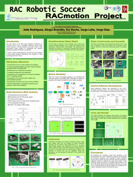
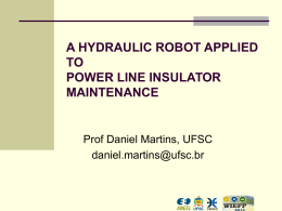
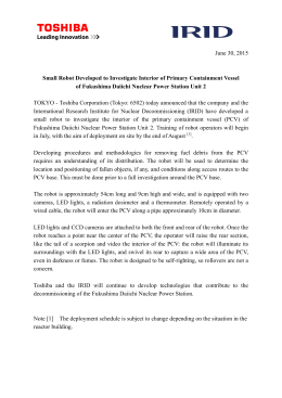
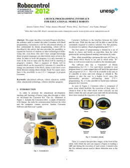
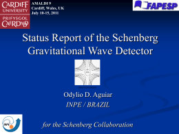
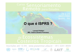
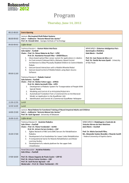
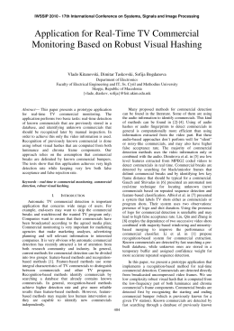
V SBAI - Autores file:///media/disk/T rabalho/Tese_Eduardo_Freire/artigos/E... V Simpósio Brasileiro de Automação Inteligente Lista de Autores A. A. Susin 1148 A. C. Zanin 1145 A. Zanini 1111 A. R. Nogueira 1111 Adão de Souza Jr. 1080 Adelardo Adelino Dantas de Medeiros 1102 1153 Adilson S. Engelmann 1129 Adolfo Bauchspiess 1045 Adriano G. A. Siqueira 1146 1147 Aldayr Dantas de Araújo 1037 Alderico R. de Paula Jr. 1032 Alessandra Bussador 1025 Alessandro L. Rangel 1101 Alexandre Augusto Angelo de Souza 1078 Alexandre Evsukoff 1158 Alexandre I. Gervini 1039 Alexandre Sanfelice Bazanella 1061 1064 Alexandre Scaico 1083 Alexandre da Silva Simões 1033 Alfons Crespo 1156 Allan Aminadab André Freire Soares 1102 Allan Kardec D. Barros 1055 Aluizio F. R. Araújo 1024 Amit Bhaya 1115 Ana Luísa Nóberga Distéfano 1139 Ana Maria F. Fileti 1125 Anderson Vinícius de Medeiros 1116 André Laurindo Maitelli 1114 1116 Angelo Perkusich 1083 1139 Anna Helena Reali Costa 1033 Antonio A. R. Coelho 1105 Antonio C. G. é 1117 Antonio Luiz S. Ferreira 1057 Antonio Marcus Nogueira Lima 1031 1062 1106 1107 1124 1 de 8 18-10-2008 20:19 V SBAI - Autores file:///media/disk/T rabalho/Tese_Eduardo_Freire/artigos/E... Eduardo Marques 1092 Eduardo O. Freire 1086 1122 Elaine Yassue Nagai 1118 Elder M. Hemerly 1040 Eliete M. de O. CaldeiraA 1110 Emerson A. D'Aquino 1158 Esmeraldo dos Santos Filho 1055 Eugenio Silva 1117 Evangivaldo A. Lima 1089 F. Gomide 1030 F. P. Coelho de Souza 1148 Fábio Meneghetti Ugulino de Araújo 1004 1135 Fátima N. S. Medeiros 1048 Fabrizio Leonardi 1047 Fernando D. Penha 1162 Fernando J. Von Zuben 1059 1076 1103 Flávia Oliveira Santos de Sá Lisboa 1027 Flávio Neves Jr. 1018 1019 1100 Flavio Cesar Faria Fernandes 1152 Flavio Tonidandel 1138 Florival R. Carvalho 1125 1166 Flávio Neves Junior 1074 1077 1078 1094 Francisco Yastami Nakamoto 1136 Francisco das Chagas Mota 1037 Fávio C. Malinowski 1074 George A. B. de Araújo 1047 Geraldo Cezar Correa 1028 Geraldo F. Silveira 1067 1065 Germano L. Torres 1129 Gernot Richter 1023 Ginalber Luiz de Oliveira Serra 1134 Gladstone B. Alves 1063 Guilherme Augusto Silva Pereira 1029 1052 Guilherme de A. Barreto 1024 Gustavo A. Neumann 1157 Gustavo E.A.P.A. Batista 1091 Gustavo Henrique da Costa Oliveira 1128 3 de 8 18-10-2008 20:19 DEVELOPMENT OF A MOBILE ROBOT WITH MULTIPLE SENSING LEVELS AND BEHAVIOR-BASED CONTROL SYSTEM EDUARDO O. FREIRE1, RAQUEL F. VASSALLO, TEODIANO F. BASTOS-FILHO, MÁRIO SARCINELLI-FILHO Department of Electrical Engineering, Federal University of Espirito Santo Av. Fernando Ferrari, S/N, 29060-900,Vitoria-ES, Brazil E-mail: [email protected] Abstract This work reports the development and prototyping of an autonomous wheeled mobile robot. It is equipped with six types of sensors, which are shaft encoders, ultrasonic transducers, infrared proximity sensors, contact sensors, temperature sensor and monocular vision. These sensors interact among themselves to get accurate information about the surrounding environment in order to allow the robot to navigate safely and autonomously. As an experiment to demonstrate some capabilities of the prototype robot, a behavior called Exploration is here described, which is designed to be part of the control layers of the behaviorbased control system implemented. As exemplified in the paper, this behavior assures that the robot is able to navigate avoiding any obstacle in its path. Another behavior, called Object_Recognition, is also available, which gives the robot the ability of recognizing some obstacles in order to improve its navigation. Thus, the user has the additional flexibility of programming the robot to do some specific tasks associated to specific objects, like to cross an opened door. Keywords: Mobile Robotics; Sensing Systems; Agents; Behavior-Based Control System; Object Recognition. 1 Introduction The Robotics research group of the Department of Electrical Engineering of the Federal University of Espírito Santo, Brazil, has built a differential-drive mobile robot prototype called Brutus, which is shown in Figure 1. It is assembled as a five round platforms, thus resembling to a cylinder. The bottom face of the bottom platform has two independent DCdriven wheels mounted in a diametrical line, which are responsible for driving the robot. It also has two free wheels that are mounted in a diameter perpendicular to the line of the driven wheels, which are used for guaranteeing the robot balance. Although been designed to navigate autonomously, a minimal additional setup is also included in the prototype in order to allow teleoperating it. The computational setup onboard the robot comprises a main Pentium MMX 233 MHz-based motherboard and two secondary Motorola MC68HC11-based processing boards. One of the secondary processing-boards is responsible for controlling the speed of the two DC motors while the other processes the information coming from the sensing system installed onboard the robot. The main onboard computer communicates with the two secondary processing boards, as well as with a frame grabber and a CCD camera. It is responsible for some image-processing procedures designed to allow the robot to recognize some objects present in its working environment and for the management of the whole control system. The whole control system of this robot is a behavior-based one (Brooks, 1986; Arkin, 1998). One of the behaviors designed to the robot is to avoid collisions when moving. For allowing obstacle avoidance, the robot is equipped with a ring of sixteen ultrasonic transducers distributed along the outer circle of one of the robot platforms, a set of proximity infrared sensors and some contact sensors. It is also equipped with a single CCD camera (see Figure 1) located at the center of the upper platform, which is intended to allow Brutus to recognize obstacles in its path. More specifically, the robot is able to recognize an obstacle out of a small group of obstacles previously defined, whenever it detects this obstacle in its path. This mixed sensing system is designed as a distributed system, which ensures its proper insertion in the whole behavior-based control system (Freire, 1997; Xavier and Schneebeli, 1998; Bastos-Filho et al., 1999). In the sequence of this paper, the sensing system implemented onboard Brutus is described, as well as the control system that manages the information coming from it. Finally, an experiment where the robot Brutus navigates in a corridor where some obstacles are present is reported, whose goal is to show that the sensing system installed onboard the robot assures its safe navigation. Grants from CAPES and CNPq, all from Brazil, supported this work. 1 CCFT/Tiradentes University Av. Murilo Dantas, 300, 49030-270, Aracaju-SE, Brazil Figure 1. The mobile robot Brutus. 2 The Sensing System of Brutus Brutus has four sensing levels. The first one is composed by two shaft-encoders coupled to the driven wheels. They allow determining the robot speed and displacement, thus providing the necessary feedback when controlling the robot position and some odometry. The second sensing level includes two independent subsystems. The first one is a ring of 16 Polaroid 6500 series electrostatic transducers (see Fig. 2), which are responsible for sensing the environment to detect obstacles in the robot path. The use of ultrasonic transducers is due to their low cost, but they are also very sensitive to the obstacle orientation and its effective reflection area1, thus generating some misinformation. Besides, those used in Brutus are also unable to determine the distance to the obstacles in a dead zone of 15 cm (Bastos-Filho, 1994). The second subsystem included in the second sensing level of Brutus is a set of four SHARP GP2D02 infrared proximity sensors (Fig. 2), whose goal is to prevent any accident caused by the problems associated to the ultrasonic transducers used. This sensing subsystem is able to detect the presence of an obstacle in the dead zone of the ultrasonic sensing subsystem. Thus, if an obstacle is not detected by the ultrasonic sensing subsystem, it can be detected by the infrared sensing subsystem, thus increasing the robot safety. The third sensing level is designed to prevent any damage to the robot in case of a collision. It is composed by four micro-switches installed in a bumper added to the bottom platform of Brutus, in the same angular positions of the infrared proximity sensors. If a collision happens, at least one microswitch is activated. Then, the robot is commanded to stop, to go back for a while and then to turn itself in opposition to the direction of the activated microswitch. Thus, this sensing level is complimentary to the previous one, and its goal is to increase the robustness of the whole sensing system. The processing board responsible for controlling U ltraso n ic T ran sd uce rs (1 6) Figure 2. The sensing subsystems of Brutus (the four microswitches in the bumper and the camera are not shown). 1 The object orientation should be perpendicular to the ultrasonic transducer emission axis. If the object orientation differs by more than 17o from the optimal one, the object will not be detected. the DC-motors speed also processes data from the infrared proximity sensors and the micro-switches. By its turn, the ultrasonic sensing subsystem is controlled by the other secondary processing board. These three sensing levels are responsible for the robot safety, or the low-level navigation system. 3 The Ultrasonic Sensing Subsystem Instead of being fired all at once, the 16 ultrasonic transducers of Brutus are fired one at each time, with a period defined by a priority function associated to each transducer in each moment. Then it is possible to observe more frequently the directions where the probability of a collision is greater, thus allowing a safer navigation. The priority value pk(t) assigned to the k-th ultrasonic transducer depends on its angular position around the robot platform, as well as the distance from the robot to the object reflecting the ultrasonic signal in the instant t. The empiric function pk ( t ) = (d inf − d new ) + (d old − d new ) + vetcte(k ) + pk ( t − 1) (1) is used to calculate this priority, where dinf is the maximal distance measurable (about 5 m), dnew is the newest measure and dold is the previous measure provided by the k-th transducer. By its turn, vetcte is a vector containing the sixteen minimum priority values assigned to the ultrasonic transducer, which depends only on the position of the corresponding transducer in the ring. The first term of (1) depends on the distance between the ultrasonic transducer and the object. The second one depends on how fast the robot approaches the object and the third one depends on the position of the ultrasonic transducer around the robot platform. Then, (1) shows that the priority pk is initialized with a constant value depending only on the position of the k-th transducer around the robot platform and is integrated along the time. Whenever an obstacle is detected, (1) is calculated for each one of the 16 ultrasonic transducers. However, the term that depends on how fast the robot approaches the object is considered just for the ultrasonic transducer that was fired, because at that moment only it measures a new distance value. As the priority calculation is finished, the transducer with the highest priority is selected as the next to be fired. Then, its two neighbors (Tk-1 and Tk+1) are chosen as the next to be fired. The reason for this is to cover a larger angle, thus reducing the probability of not detecting bad oriented objects. After firing these three ultrasonic transducers, another selection takes place. Every time an ultrasonic transducer is fired, its priority is made equal to zero, in order to put it in the end of the queue, unless it has detected an obstacle at a distance smaller than 65 cm. In this case, it will receive the maximum priority to guarantee that it will keep fired until the object is no longer detected. Tests with the robot at an environment with none object closer than 1 m to it showed that the frontal transducer T0 (the most important one) was fired 20 times more than the back transducer T8 (the least important one). This result demonstrates the efficiency of the term dependent of the position of the transducer around the robot platform in (1). 4 The Monocular Visual System Vision corresponds to the fourth sensing level of Brutus. A monocular system is installed to allow the robot to recognize some objects in its working environment. This increased the level of autonomy of Brutus, for allowing it to make decisions on which task to perform when finding a certain obstacle. (a) Original image 4.1 The Image-Processing Task The image-processing task implemented is able to allow the robot to identify obstacles like walls, corners or edges, table legs and doorframes (open or closed doors). A first descriptor for identifying images containing these obstacles is the number N of vertical lines in the image. For instance, a wall does not have vertical lines, a table leg corresponds to two vertical lines (as well as doorframes) and an edge or a corner corresponds to just one vertical line. Thus, the first step is to segment the image in order to select the meaningful vertical lines, here considered as the vertical lines spanning over 60% of the image height (640x480 pixels bitmaps in a 8 bit grayscale). The reason for considering only meaningful vertical lines is to deal only with objects in the first plane of the image. In addition to the vertical lines spanning, vertical lines too close are also considered as a single vertical line (the minimum distance, here, is 26 pixels). Besides, for distinguishing objects like doorframes and table legs, one needs to consider the distance D in pixels between two adjacent vertical lines. It is possible to use this distance as a valuable descriptor because the images are got from approximately the same distance, thus characterizing a 2½-D system. Fig. 3 shows an image acquired when the robot approached an open door. The original image, the binary image obtained after selecting the vertical lines and the binary image resulting from the selection of the meaningful vertical lines are presented in Fig. 3. In this case, the obstacle was correctly identified as an open door. The number of meaningful vertical lines and the distance between them allowed determining that the obstacle was a doorframe. In order to distinguish the open door from a closed door, a third image descriptor is also used: the average gray level in both sides of the outer vertical lines. These values are calculated considering a horizontal line about the middle of the image height. The gray levels of each pixel on this line in each image region are then considered, resulting in the average values T1 and T2. For the example in Fig. 3 one can notice that the average gray level in the right side and in the left side (b) Binary image showing the vertical lines detected. (c) Final image showing only the meaningful vertical lines. Figure 3: Example of object recognition. of the image are not so different. In the case of a closed door, however, they would be much different, once the door is much darker than the background in the left side of Fig. 3a. 4.2 The Object-Recognition Step After having determined the descriptors associated to an image, the robot should determine which object it is facing. The basic variable used to implement the recognition system engine is the number of meaningful vertical lines detected (N). In addition, the distance between two different vertical lines (D) and the average gray-levels in the two regions of the original image outer the meaningful vertical lines (T1 and T2) are also used. The last descriptor used the difference between these two average gray-levels (DT). The way these variables are used is illustrated in Table 1, and is based on the previous knowledge of which objects the robot should be able to identify and their main characteristics (relative widths, gray levels, etc.) as well. This resulted in the "rule base" depicted in the table, where the "rules" were defined after analyzing a set of about twenty photos of different Table 1: The "rule base" used in the recognition engine. Characteristics of the descriptors N=0 100 ≤ DT ≤ 140 DT > 140 N=1 or T1 and T2 < 150 Otherwise 100 ≤ DT ≤ 140 44 ≤ D < 77 Otherwise DT < 100 N = 2 77≤ D <154 100 ≤ DT ≤ 140 Otherwise 154 ≤ D N≥3 Object Wall Opened Door 9 ! 9 < < Closed Door " ! Edge or Corner Opened Door Closed Door Table Leg Opened Door Closed Door Edge or Corner Unknown " 7 = ' > 42 & ) 3 ' * " 3 O b ject_ R e co gn ition objects in different condition regarding environmental illumination, ground pattern, background objects, etc. A remarkable note is that for a different environment one should "recalibrate" the recognition engine depicted in Table 1. The same should be done regarding the threshold value applied to each pixel to generate the binary images, the minimum relative height of the meaningful vertical lines and the minimum distance between two meaningful vertical lines. 5 $ ! The Behavior-Based Control System The control system implemented onboard Brutus is shown in Fig. 4, and includes the low-level navigation control system responsible for avoiding any obstacle in the robot path and the monocular vision subsystem that recognizes the obstacles. It is derived using the framework proposed by Xavier and Schneebeli (1998). The whole control architecture is a behavior-based one and uses continuous response codification, through the two DC-driven wheel speeds, and a priority-based arbitration scheme as the method of behavior coordination (Arkin, 1998). The behaviors are implemented through agents (sensor agents, behavior agents and actuator agents) as elementary building blocks (Xavier and Schneebeli, 1998). This control system includes 26 primitive sensor agents (S0 to S15, corresponding to the 16 ultrasonic transducers, I0 to I3, corresponding to the four infrared sensors, B0 to B3, corresponding to the four contact sensors, and Encoder1 and Encoder2, corresponding to the two shaft encoders). It also includes two virtual sensor agents (Ultrasonic_Sensor and Camera_Sensor), four virtual actuator agents (Go_Ahead, Rotate, Activate_Motor and Cam_Motor) and one primitive actuator agent (PI). At the behavior level, it has two behavior agents (Collision_avoidance and Recognize) that are responsible for the robot navigation avoiding obstacles and for the obstacle recognition. All these agents are connected in order to implement three control levels: Motor_Control, Exploration and Object_Recognition (see Fig. 4). Following, it is described how the be- 1 2 2 ' 3 ' * %( ' ) 7 & ) & CHAN NE L " # 1 ) 5, ) * " 3 8,9:,1 2 ; 8,9:,1 2 ; . * %/ ) E x p lora tio n % & ' ( ) & *+, & 1 ) 5,* +6 & CHAN NE L - 0 M o to r_C o ntrol Figure 4. The agent-based control system already implemented onboard Brutus. havior-based control system operates in order to implement the control levels Motor_Control and Exploration. The virtual sensor agent Ultrasonic_Sensor receives information from the 16 ultrasonic transducers (primitive sensor agents S0 to S15), executes the range measurements and verifies which is the lowest distance measured and which transducer measured it. The information on the lowest distance obtained is sent to the virtual actuator agents Go_Ahead and Rotate, through the behavior agent Collision_Avoidance. These agents will define the robot speed, which will be informed to the virtual actuator agent Activate_Motor. The primitive actuator agent PI is who sends the PWM signals (corresponding to the setpoints received) to the motor drivers. While no obstacles are detected closer than 1 m to Brutus, it keeps moving at 80% of its maximum speed (which is about 0.5 m/s). This speed limit is a constraint used to increase the robot safety. If an obstacle is detected closer than 1 m to the robot, its speed is reduced as this distance gets lower, following the sequence given in Table 2. During this approaching, the virtual actuator agent Go_Ahead is the only one responsible for controlling the virtual actuator agent Activate_Motor. Whenever an obstacle is detected at a distance smaller than 65 cm, the behavior agent Collision_Avoidance receives a message from the agent Ultrasonic_Sensor informing what transducer has detected an obstacle at such a distance. Then, the agent Collision_Avoidance will activate the agent Rotate, at the same time that deactivates the agent Go_Ahead, in order to allow the robot to escape from the detected obstacle. This agent will send the setpoints of speed to the agent Activate_Motor, thus driving the robot to escape from the obstacle. During one second, the robot will turn itself (controlled by the agent Rotate) in the direction opposite to the detected obstacle, in order to avoid it. After this, the Rotate agent is deactivated and the control of the Activate_Motor agent returns to the Go_Ahead agent. If the turn around movement were not enough to avoid the obstacle, another ultrasonic transducer would detect the same obstacle. Then, the turn around movement would be repeated until the obstacle is no more detected. If one of the ultrasonic transducers located at the front semicircle of the robot (T0 to T4 or T12 to T15) detects an obstacle, a speed reduction or a turn around takes place, according to the distance. Obstacles detected by one of the transducers T0 to T4 causes a turn around to the left side if the distance is smaller than 65 cm. On the other hand, if the obstacle is detected by one of the transducers T12 to T15, at the same distance range, the turn around will be to the right side. For any of these transducers, however, only a speed reduction is executed if the distance is in the range of 75 cm to 1 m. For distances greater than 1 m, no special action is taken, and the robot keeps going ahead (see Table 2). The transducers located at the back semicircle of the robot, by their turn, are not allowed to cause any turn around, but just speed reduction, because any movement to the rear correspond to evasive maneuvers. If the transducer T0 detects the object, the agent Activate_Motor will receive a message informing it to turn around its own central axis. During this spin movement, which spends 2.5 s, the agent Activate_Motor will not accept any new setpoint. However, if an obstacle is detected at a distance in the range of 65 cm to 75 cm from the robot, the action taken is completely different. The Ultrasonic_Sensor agent activates the Camera_Sensor agent, and not the Collision_Avoidance agent. This agent activates the Cam_Motor agent in order to rotate the camera towards the ultrasonic transducer that detected the obstacle. This rotation is an open-loop task performed by a PIC 16F84 microcontroller that drives a stepping motor, over which the camera is mounted. This open-loop task of camera rotation spends some time, in which the agent Camera_Sensor keeps paused. Then, the Camera_Sensor agent gets a frontal image of the obstacle and sends it and an activation message to the Recognize agent, which will perform the task of object recognition, like characterized in Section 4. During this time, the agent Collision_Avoidance is activated only for stopping the robot completely (the robot keeps stopped during three seconds, in order to allow getting and processing an image). Once the obstacle in front of the robot has been identified, the user can de- fine which behavior should be activated, from a list of available behaviors. For the example reported in the next section, however, the robot simply continues moving ahead, after the pause to get an image and process it. In the example shown, it keeps moving ahead with 60% of its maximum linear speed during one second, in order to assure that the distance to the obstacle keeps lower than 65 cm. This is necessary to guarantee that the robot will not stay getting an image of the same obstacle more than once. In summary, when the robot approaches an obstacle, the whole sequence of Table 2 is followed. If a micro-switch in the bumper is activated (primitive sensor agents B0 to B3), it means that the robot collided to an obstacle. By its turn, if an infrared proximity sensor detects an obstacle (primitive sensor agents I0 to I3), it means that the robot is about colliding. In both cases, the action will be the same, because something must be done quickly. The primitive sensor agent that is activated sends a message to the behavior agent Collision_Avoidance, which immediately sends a message to the virtual actuator agent Go_Ahead informing it to stop the robot. After stopping the robot, the Collision_Avoidance agent will check which primitive sensor agent (B or I) detected the obstacle, in order to determinate the direction in which the obstacle is. After this, it will send a message to the Go_Ahead agent to move the robot back for a while. In the sequence, it will activate the agent Rotate in order to turn the robot around its own central axis in opposition to the direction of the detected obstacle. This sequence of actions allows the robot to escape from the obstacle it has collided to or is about colliding to. Then, the agent Go_Ahead resumes the control, and the robot starts going ahead again. 6 An Illustrative Example In order to illustrate the performance of this control system, the robot is tested in a corridor containing some obstacles. Fig. 5 shows the layout of the corridor and the position of the obstacles, as well as the trajectory the robot followed (recovered through the odometry introduced by the shaft encoders). The actions performed by the robot are described in the sequence. Firstly, it keeps moving ahead until m Table 2. Actual Linear Speed of the Robot (in % of the Maximum Value) as a Function of the Distance Robot-Obstacle Lowest Distance Measured Dmin > 100 cm 100 cm > Dmin ≥ 90 cm 90 cm > Dmin ≥ 75 cm 75 cm ≥ Dmin ≥ 65 cm 65 cm > Dmin Linear Speed 80% 70% 60% STOP TO ACQUIRE AND PROCESS AN IMAGE. RESTART MOVING IN 3 S TURN Figure 5. Navigation of Brutus in a corridor with obstacles (units are meters). an ultrasonic sensor detects the obstacle in the form of an edge, causing Brutus to deviate from its original path. Following, Brutus continues moving ahead until the frontal ultrasonic transducer detects the obstacle corresponding to the black square. Then, it turns around its central axis to the left side for a while, thus going out of the obstacle. In the sequence, Brutus continues moving ahead, in the direction of another wall in the corridor. Then, the frontal ultrasonic sensor detects the presence of this obstacle and Brutus makes another turn around movement to the left side, and continues moving ahead, now to the left side of the corridor. As it can be seen in the figure, during this part of its navigation a side ultrasonic sensor detects the presence of the wall and causes Brutus to deviate from it, to the left side. The line about the middle of the corridor, which represents the path the robot followed, registers this sequence of events. 7 Other Features Added to Brutus Besides being able to navigate autonomously, through the control system embedded on it, teleoperation is also available (Fig. 6 and Fig. 7). This is possible because of some specific hardware pieces installed on the topper platform. The first of these pieces is a TV transmitter board, used to transmit the images acquired by the onboard camera to the remote user. The second feature is a radio link responsible for transferring to Brutus commands that are decoded by the same PIC microcontroller responsible for rotating the camera during the autonomous navigation. Based on these specific hardware pieces, the robot can now be teleoperated from a local PC, a remote one (through the INTERNET), as well as by using a voice command box or a joystick (Freire et al., 2000). 8 Conclusion The development and prototyping of a wheeled mobile robot is here described. The sensing system onboard it guarantees that the robot is able to navigate without colliding to any obstacle in its path, as well as to recognize some obstacles detected, so that tasks more complex than just to survive can be accomplished. Currently, the prototype is only able to navigate avoiding obstacles, as exemplified in the paper. Mobile Robot Brutus Remote PC Local PC RF Modem Joystick Internet Recognition of Voice Commands Figure 6. Teleoperation scheme. Figure 7. Hardware used to teleoperate the robot Brutus. In addition, a monocular vision system is being incorporated to its behavior-based control and sensing system in order to allow accomplishing more complex tasks which will be based on the recognition of the obstacles. References Arkin, R. C (1998). Behavior-Based Robotics, The MIT Press. Bastos-Filho, T. F. (1994). Seam Tracking and Analysis of Automatic Arc-Welding Environments through Ultrasonic Sensors, Ph.D. Thesis, Complutense University of Madrid, Spain (written in Spanish). Bastos-Filho, T. F., Sarcinelli-Filho M. and Freitas, R. A. C. (1999). A Multi- Sensorial Integration Scheme to Help Mobile Robot Navigation through Obstacle Recognition, Proceedings of the 7th IEEE International Conference on Emerging Technologies and Factory Automation, Vol. 1, Barcelona, Spain, pp. 549-558. Brooks, R. A. (1986). Achieving Artificial Intelligence through Building Robots, AI Memo 899, Massachusetts, MIT, USA. Freire, E. O. (1997). Development of an Ultrasonic Sensing System for Agent-Based Controlled Mobile Robot, M. Sc. Thesis, Federal University of Espírito Santo, Vitoria, Brazil, 1997 (written in Portuguese). Freire, E. O., Vassalo, R. F., Alves, R. L. and BastosFilho, T. F. (2000). Teleoperation of a Mobile Robot through the Internet, Proceedings of the 43rd Midwest Symposium on Circuits and Systems, Lansing, MI, USA. Xavier, J. E. M. and Schneebeli, H. A. (1998). A Framework Based on Concurrent ObjectOriented Programming for Building BehaviorBased Control Systems for Mobile Robots, Journal of the Brazilian Computer Society 4(3): 27-34.
Download