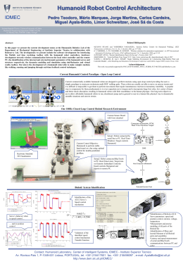
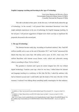
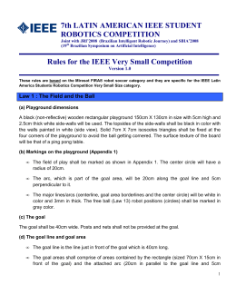
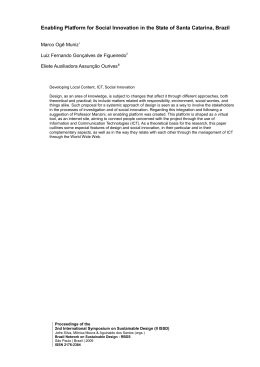
A HYDRAULIC ROBOT APPLIED TO POWER LINE INSULATOR MAINTENANCE Prof Daniel Martins, UFSC [email protected] Authors Martins, Daniel, [email protected] De Negri, Victor Juliano, [email protected] Simas, Henrique, [email protected] Pieri, Edson Roberto De, [email protected] Stemmer, Marcelo, [email protected] Universidade Federal de Santa Catarina Departamento de Automação e Sistemas Departamento de Engenharia Mecânica Florianópolis-SC Introduction Robot requirements Kinematics conception Operational mode Software 1. INTRODUCTION Most robots are developed for industrial automation and used in processes such as welding, assembling and transporting. Another class of robots are developed for special operations, such as recovery of the surface of turbine blades; drilling of the fuselage of aircrafts among others. In Brazil, many power transmission lines are located in coastal regions and therefore have a strong process of degradation due to the weather. The main problem is concentrated in the loss of dielectric strength of insulators due to the accumulation of salt. 1. INTRODUCTION Usually, the service is performed by means of a hydraulic crane and an improvised mechanism for washing, with two operating modes: a) manual, where a crane aerial bucket is used to drive the operator close to the insulators and from there, an operator run the service through a water jet; and, b) remote, where the operator remotely controls the direction of the water jet, with the assistance of a two degrees of freedom device installed at the end of the crane. . 1. INTRODUCTION This research is concerned to the automation of the task of washing insulators of distribution power line networks, through the design and construction of a service manipulator remotely operated that aims to: a) increase the efficiency of washing, b) facilitate the operation by performing the motion control in the Cartesian space and, c) allow the inspection and the control motion with the aid of two cameras. 1. INTRODUCTION The methodology of study and the kinematic conception are presented and discussed according to the arrangements of wires and poles within a specified workspace. Results of task washing simulations are presented in a virtual ambient and, at the end, the resulting service manipulator developed, already mounted on a truck, is shown 2. ROBOT KINEMATICS REQUIREMENTS AND THE WORKSPACE Improve the system security and isolation of the truck; Improve the quality of the washing of insulators; Reduce cleaning time per post; Build a cleaning-head to direct the water jet composed with two servo-motors; Develop routines for automatic trajectories. 2. ROBOT KINEMATICS REQUIREMENTS AND THE WORKSPACE The robot will be used in 13.8kV distribution power lines The most complex post structure that the robot will operate is called N1N1N3 CEMAR structure The truck will stop on the roads side-by-side with the post in a such way the washing head must be able to reach, with its water jet, both sides of any insulator fixed in the posts (in the manual operation this is not achieved). The robot must be user friendly to control. N1N1N3 CEMAR post structure 2. ROBOT KINEMATICS REQUIREMENTS AND THE WORKSPACE 3. KINEMATICS CONCEPTION 3. KINEMATICS CONCEPTION 3. KINEMATICS CONCEPTION 3. KINEMATICS CONCEPTION 3. KINEMATICS CONCEPTION The dimensions of the commercial crane model specified to be acquired (3.5m high, 5.5m in the first link and 6.35 for the second link) The inclusion of a third link with a length of 2m (to conduct the nozzle) In agreement with resolution number 12/CONTRAN (Brazilian Counsel of Transit) of 06/02/1998, published in 07/02/1998, the maximum dimensions for this special motor vehicle should be: maximum width: 2.60m and maximum height: 4.40m; Inclusion of a “V” format in the second link. 3. KINEMATICS CONCEPTION 3. KINEMATICS CONCEPTION - CAD MODEL 3. KINEMATICS CONCEPTION - CAD SIMULATION 3. OPERATIONAL MODE Joint-to-joint movements - where the operator controls one joint each time; Pre-washing - where the operator acts leading the end-effector in the Cartesian space. This operational mode keeps the last three joints operating on joint-tojoint control strategy. The end-effector orientations are kept fixed in relation to the base. Washing - in this operational mode the latter two joints are responsible for guiding the water nozzle. The joints act together to increase the area of operation of the washing. 4. SOFTWARE AND KINEMATIC CONTROL SYSTEM The control system design was implemented starting from a Channel/Instanced Petri net (C/I net) 4. SOFTWARE AND KINEMATIC CONTROL SYSTEM The system architecture was modeled through API’s (Application Programming Interface) that incorporate the structural and procedural aspects. The computational model is based on an Open System for Robot. This computational model allows the development and implementation of the computer program to control the system, and also to develop alternative control strategies. 4. WHMI – Wireless Human-Machine Interface View - Shows the visualization of the tools from the camera mounted on the end-effector; Jet - Turns on or off the water jet tool; Increment - Increments the robot Cartesian position; Decrement - Decrements the robot Cartesian position; Stop - to immediately stop the robot. 4. CONTROLLER The controller manages the tasks of the robot using the computer system and the servo-amplifier. The controller was modeled logically accordingly in agree with the following software components: GUI (Graphical User Interface): It models the graphical user interface that will be available in the HMI. Tool: It models the tools and jet inspector that will be used by the robot. Robot: It models the robot manipulator. TG (Trajectory Generator): It models the trajectory generator to be used by the robot. The controller will operate in an Industrial PC (model 1036 from National Instruments®) with bus PXI (PCI eXtensions for Instrumentation) card with central processor 8106 and control movements card 7344, all from National Instruments. 4. CONTROLLER 4. DIRECT AND INVERSE KINEMATICS ALGORITHM The functionality of the TG system depends on the functions of direct and inverse kinematics of the robot. Except the last two joints (joints responsible for the direction of the water jet), the others rotating joints are driven by hydraulic cylinders. Therefore, procedures have been developed for calculating the angular positions and velocities of the joints as a function of the positions and velocities in linear hydraulic cylinder according to each mechanical assembly. Similarly, the reverse procedure was also developed, that is, the conversion of positions and linear velocities of the cylinders into the angular positions and velocities of the joints. Additional procedures implement the geometric Jacobian and the analytical inverse kinematics. All these procedures work together with the TG system which in turn is integrated into the control system of the robot. 5. CURRENT STAGE OF CONSTRUCTION OF THE ROBOT Conclusion This work presented a systematic approach and the kinematic design of an electro-hydraulic robot designed to clean, by washing with a water jet, insulators of 13.8kV distribution network poles. The kinematic conception was developed with the aid of small-scaled models that were computationally validated through several simulation softwares. We presented the main aspects of control system, such as diagrams C/I net and layout of Human-Machine interface. The main specification treated in this project was the security of operator, robot and power line distribution networks. A HYDRAULIC ROBOT APPLIED TO POWER LINE INSULATOR MAINTENANCE D e p a r ta m e n t o d e A u to m a ç ã o e S is te m a s - D A S D e p a r ta m e n t o d e E n g e n h a r ia M e c â n ic a - E M C D ir e to r ia d e E n g e n h a r ia - C E M A R G e r ê n c ia d e P la n e ja m e n to d o S is te m a E lé tr ic o - C E M A R [email protected]
Download