UNIVERSIDADE TÉCNICA DE LISBOA
INSTITUTO SUPERIOR TÉCNICO
Mechanical Design of an Anthropomorphic Robot Head
Ricardo Beira
(Licenciado)
Dissertação para obtenção do Grau de Mestre
em Engenharia de Concepção
Orientador: Doutor José Alberto Rosado dos Santos Victor
Júri
Presidente: Doutor José Alberto Rosado dos Santos Victor
Vogais: Doutor Hélder de Jesus Araújo
Doutor Alexandre José Malheiro Bernardino
Doutor Arlindo José de Pinho Figueiredo e Silva
Janeiro 2008
Título: Projecto Mecânico de uma Cabeça Antropomórfica Robótica
Nome: Ricardo Daniel Rita Beira
Curso de Mestrado em: Engenharia de Concepção
Orientador: Professor José Santos Victor
Resumo
Esta tese tem como principal objectivo o uso de ferramentas computacionais e de
cálculo para o projecto mecânico de um sistema robótico, composto por um
pescoço e uma cabeça antropomórfica de um robot humanóide.
O trabalho foi desenvolvido no âmbito do Projecto Europeu RobotCub, que consiste
num dos maiores esforços no sentido de desenvolver as capacidades de percepção
e raciocínio dos robots, integrando equipas de engenharia bem como equipas de
psicologia, medicina e neurociência, visando criar robots que desenvolvam as suas
capacidades perceptuais, motoras e cognitivas ao longo do tempo, de forma
semelhante ao desenvolvimento de crianças ou recém-nascidos, permitindo assim,
testar os princípios subjacentes a esses mecanismos biológicos. A plataforma final,
o iCub, terá aproximadamente 90 cm de altura, 23 kg de peso e um total de 53
graus de liberdade.
Para que esta cabeça robótica seja dotada de propriedades similares à de uma
criança de dois anos, foi feito um levantamento, não só das várias especificações
que o sistema biológico possui, do ponto de vista anatómico e comportamental,
mas também das soluções utilizadas noutros robots já existentes.
No final, foi produzido um modelo funcional da plataforma, sendo testadas e
optimizadas as suas performances mecânicas.
Palavras-chave: Robots Humanóides; Projecto Mecânico; Análises Dinâmicas;
Selecção de Actuadores; Mecanismos Robóticos; Coordenação Visuomotora
I
Title: Mechanical Design of an Anthropomorphic Robot Head
Abstract
This Thesis’s main objective was to develop an anthropomorphic robot head,
composed by a neck and a vision system, using computational and analytical tools
for its mechanical design.
The work was developed in the framework of the European Project RobotCub which
is one of the biggest efforts to develop the capacities of perception and reasoning of
robots. It integrates research groups of engineers as well as teams of psychology,
medicine and neuroscience aiming to create robots can be able to develop their
own perceptual, motor and cognitive capacities along the time, similar to the
development of children or rear-born, thus allowing to test the underlying principles
of these biological mechanisms. The final platform, the iCUB, is approximately 90
cm tall, with 23 kg and with a total number of 53 degrees of freedom.
So, as this robot head was designed to have similar properties of a two-year-old
child’s head, some specifications were based, not only on the other different
solutions, used in several humanoid robots, but also on the biological system
anatomical and behavioral data.
In the end, a platform prototype was produced, tested and optimized, in order to
increase its mechanical performances.
Keywords: Humanoid Robots; Biologically Inspired Robots; Mechanical Design;
Dynamic
Analysis;
Actuators
Selection;
Robotic
Mechanisms;
Visual-motor
coordination
II
Acknowledgements
I would like to express my great admiration for Professor José Santos-Victor and
appreciation for all the help he patiently gave, not only during the thesis project but
through out all the MSc. period.
His general knowledge, expertise, methodology and humour greatly surpass the
context of this thesis and it will certainly be invaluable to me through out my
career.
Very special thanks to Miguel Praça, for the endless efforts in providing me with all
the technical support to come through with this project. His initiative and work
methodology has served me has an important source of inspiration.
I would like to thank also to my colleagues Manel, Vargas, Alex, Rui Santos,
Rodrigo and Ricardo Nunes, for their dedication and friendship during this period.
III
IV
Index
Resumo ....................................................................................................... I
Abstract ..................................................................................................... II
Acknowledgements .................................................................................. III
Index .......................................................................................................... 1
1. Introduction ........................................................................................... 3
1.1. Research Context..................................................................................................................... 3
1.2. Benchmarking ........................................................................................................................... 6
1.3. Our Approach ............................................................................................................................ 8
1.4
Thesis Organization ......................................................................................................... 11
2. Head Specifications .............................................................................. 13
2.1. Anatomical Data ..................................................................................................................... 13
2.2. Robot Head Specifications .................................................................................................. 18
3. Model Development .............................................................................. 23
3.1. Neck Mechanism .................................................................................................................... 24
3.1.1. Flexible Neck Solution ........................................................................................................................................... 25
3.1.2. Parallel Mechanism Solution ............................................................................................................................... 27
3.1.3. Serial Mechanism Solution .................................................................................................................................. 34
3.2. Eyes Mechanism ..................................................................................................................... 38
3.3 Actuators Selection................................................................................................................. 40
3.4. Eyelid Mechanism .................................................................................................................. 43
3.5. Material Selection .................................................................................................................. 46
3.6. Assembly ................................................................................................................................... 47
3.7. Sensors and Electronics ...................................................................................................... 49
3.6 External Cover.......................................................................................................................... 52
4. Performance ......................................................................................... 55
5. Conclusions/ Future Work .................................................................... 59
6. References............................................................................................ 63
1
2
1. Introduction
This thesis describes the design of a robot head [Beira et al., 2005], developed in
the framework of the RobotCub project [Sandini et al., 2004]. This project’s goal
consists on the design and construction of a humanoid robotic platform, the iCub,
for the study of human cognition. The final platform will be approximately 90cm
tall, with 23 kg and with a total number of 53 degrees of freedom.
For its size, the iCub is the most complete humanoid robot currently being
designed, in terms of kinematic complexity. The eyes can also move, as opposed to
similarly sized humanoid platforms.
Specifications were based on biological, anatomical and behavioural data, as well as
tasks constraints. Different concepts for the neck design (flexible, parallel and serial
solutions) were analyzed and compared with respect to the specifications. The eye
and eyelids mechanical design is presented, as well as a description of the head
external cover and electronics.
We also present the several tests made to evaluate the functional performances of
the designed head.
1.1. Research Context
The first developments of humanoid mechanical platforms started in the midseventies in Japan, when the state of computing technology (but also sensors and
vision, energy supply, etc.) was still far from what is needed even for a basic notion
of “autonomy”. Even though at that time we could not even dream of implementing
higher-level cognitive abilities as integral functions of these bodies, there were
impressive achievements of the emulation of human motor skills (walking,
grasping, even piano-playing).
Throughout the 1980’s engineering efforts went into human inspired limbs,
particularly multi-fingered hands, but it faded away when it became clear that there
are very few, if any, immediate industrial applications. Today, however, we can see
more clearly what potential benefits, i.e. direct applications but also spin-offs,
might be:
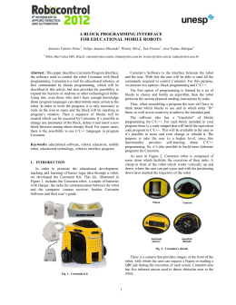
• Education: Basically there are two different uses for humanoids in
education. (i) Students build humanoids to learn in a practical exercise about their
3
mechanical construction and the complex software modules that control it. (ii)
Students use humanoids to experiment with and enhance their skills. The aim
should be to make them very easy to use, to clearly specify their interface so as to
enable non-roboticists and even students of non-engineering faculties to quickly
become familiar with the robot.
Figure 1: Examples of secondary school robots
•
Entertainment:
Robots
of
human
shape
used
for
animation
and
advertisements at exhibitions and funfairs do not depend on a highly developed set
of skills. It is usually rather their bodily appearance that attracts people because
they discover human traits in these machines. To maintain a certain “surprisefactor” over time, however, it will be necessary to constantly improve their skills.
Depending upon the target application, this may even include grasping and
sophisticated navigation, e.g. for showing visitors around, manipulating and
explaining the objects on display in a natural way.
Figure 2: Examples of entertainment robots
4
• Service: Unlike autonomous service robots that perform a more or less
limited range of special tasks with or without human supervision, a humanoid robot
can in principle use the same tools and appliances as humans and may hence
become as flexible in adapting to new tasks as a human being. If it is close enough
to human shape and size, it may also operate in totally unchanged man-made
environments. Moreover, if it is capable of receiving its tasks by carrying on a
dialogue with human instructors involving speech, gestures and facial expressions,
then it will provide a functionality that surpasses by far anything that today’s
service robots have to offer.
Figure 3: Examples Service Robots (University of Kalsruhe’s and Fujitsu’s
Service Robots)
• Prosthetics: If we think of the humanoid robot as a collection of prostheses
for limbs but to some extent also for sensors, then it becomes clear that prosthetics
and humanoid research may very fruitfully profit from each other. While there is
still little evidence that cybernetic organisms (“cyborgs”) may ever be realized or
the human mind be transferred to these machines, prostheses that afford some
autonomy of their own may become an alternative to current designs, at least until
it is possible to “re-grow” human organs.
Figure 4: RoboWalker, an example of a robotic prostheses
5
1.2. Benchmarking
Nowadays, the emergence of humanoid robots has been extensive because of
anthropomorphism, friendly design, applicability of locomotion, behaviour within
the human living environments, small size and so on. In fact, one reason for its
small size is safety: striding about in homes, a small robot is less likely to harm
people by falling on them. Another reason is that shorter limbs and appendages are
easier to move and control. To meet these demands, several humanoid robots have
been developed in these years.
One of them is Qrio [Geppert, 2001], constructed by Sony. It was designed to be
capable of entertaining people by interacting with them through movements and
speech.
Its remarkably fluid motion comes from 38 flexible joints—4 on the neck—each
controlled by a separate motor. Qrio senses its own motion through accelerometers
in its torso and feet, a function similar to that of the human inner ear. It is 580 mm
height and its weight is approximately 6.5Kg.
Figure 5: QRIO
Honda engineers created ASIMO [Hirose et al., 2001] that, with 26 degrees of
freedom (2 on the neck, fixed eyes), can walk and perform some tasks much like a
human. It is 120 cm height and weights about 52 Kg. It was the first robot able to
climb stairs and run.
6
Figure 6: ASIMO
PINO project [Yamasaki et al., 2000] was started in November 1999 and its key
concepts for this project were: develop platform for perception and behaviour
research using multiple perception channel and high DOFs; investigate robot design
that are well received by general public and develop affordable humanoid platform
using off-the-shelf components and low-precision materials. The size of the robot is
carefully designed to be the size of the 1.5 year-old kids (height 70cm). It has
26DOFs and 4.5 Kg of weight.
Figure 7: PINO
Another
miniature
humanoid
robot
is
Fujitsu's
HOAP-2
[www.automation.fujitsu.com]. This platform has been programmed to perform
moves from the Chinese martial art taijiquan, as well as Japanese Sumo wrestling
stances as well as to aid to robotics research. This robot’s weight is less then 7 kg
and its height is about 500 mm. It has a total of 25 DOFs, 2 in the neck.
7
Figure 8: HOAP-2
After analysing all this well-known solutions, we could conclude that most of the
existing humanoid systems have a simplified head with a small number of degrees
of freedom (Table 1).
In our case, since the iCub is designed to be a tool for studying the human
cognition system and as “object manipulation” plays a key role in the development
of cognitive capability, the design of this humanoid robot aims to maximize the
number of degrees of freedom of the upper part of the body (head, torso, arms,
and hands). Given that, it was established that the iCub head should have, at least,
6 degrees of freedom (3 on the neck and 3 on the moving eyes).
Robot
Head DOF
Qrio
ASIMO
PINO
HOAP-2
4
2
2
2
iCub
Moving Eyes?
Eyes DOF
-------------
6
3
Table 1: Head DOF of analyzed solutions
1.3. Our Approach
While the development of high dynamically skilled humanoid robots ([Geppert,
2001], [Hirose et al., 2001], [Yamasaki et al., 2000]) may well succeed in
8
traditional markets, the greatest challenge from a research perspective is the use of
humanoids as subjects in Cognitive Sciences [Lopes et al., 2004].
Without doubt there is no other machine conceivable on which we may simulate
more realistically the development of cognitive processes in developmental
psychology, linguistics, etc. – emulating perception and action in the same world in
which human beings grow up. The humanoid robot’s body, if equipped with a rich
set of human-like sensors, generates a stream of multimodal and multidimensional
information about the environment that very closely resembles the input to the
human perception system. The “motor side” also requires the control of actuators in
an extremely high dimensional workspace to act in the real three dimensional world
in real time, similar to what the human nervous system has to control. Research
need not be limited to study individual development; one can also imagine the
study of “inter-humanoid” relations in humanoid societies or the evolution of
collective intelligence in such swarms of humanoids.
The ICub robotic head/neck system is included in the European Project RobotCub, a
large and ambitious project of embodied cognitive systems [Sandini et al., 2004].
The RobotCub project has the twin goals of (1) creating an open and freelyavailable humanoid platform, iCub, for research in embodied cognition, and (2)
advancing our understanding of cognitive systems by exploiting this platform in the
study of cognitive development. To achieve this goal we plan to construct an
embodied system able to learn: i) how to interact with the environment by complex
manipulation and through gesture production & interpretation; and ii) how to
develop its perceptual, motor and communication capabilities for the purpose of
performing goal-directed manipulation tasks. iCub will have a physical size and
form, similar to that of a two year-old child and will achieve its cognitive capabilities
through artificial ontogenic codevelopment with its environment: by interactive
exploration, manipulation, imitation, and gestural communication.
The iCub will be a freely available open system which can be used by scientists in
all cognate disciplines from developmental psychology to epigenetic robotics. It will
be open both in software but more importantly in all aspects of the hardware and
mechanical design.
One of the tenets of the RobotCub stance on cognition is that manipulation plays a
key role in the development of cognitive capability. Consequently, the design is
9
aimed at maximizing the number of degrees of freedom of the upper part of the
body (head, torso, arms, and hands).
The iCub will have head, torso, two arms/hands and two legs. The legs will be used
for crawling but, possibly, not for biped walking. This will allow the system to
explore the environment not only by manipulating objects but also through
locomotion. For this reason, it is particularly important to equip the iCUB with
enough degrees of freedom to allow transition between sitting and crawling
posture, as well as to look down while manipulating objects lying on the floor. The
iCub is about 90cm tall, weighs 23 kg and has a total of 53 degrees of freedom
organized as follows: 7 for each arm, 8 for each hand, 6 for the head, 3 for the
torso/spine and 7 for each leg.
The mechanics, electronics and software components of the iCub are being
developed by the RobotCub’s team in parallel and synergistically. Concerning the
mechanical hardware, the legs and spine were developed by University of Salford,
UK, the arms and hands were developed by University of Pisa, Italy and the head
was developed by us, in IST, Portugal.
The eye-head sub-system will include basic visual processing primitives, as well as
low-level oculomotor control, visual, inertial and proprioceptive sensors. The iCub
will have two arms with the motor skills and sensory components required for
dexterous manipulation. From the control point of view, reaching and grasping
primitives will be implemented together with primitives to acquire tactile and
proprioceptive information. It is expected that most of the actuators of the hand
will be located in the forearm. The hands will be underactuated. This is
implemented by means of mechanical coupling either rigidly, such as using a single
tendon to bend two joints of a finger alike, or by an elastic coupling of the joints.
Underactuation also saves on space, power consumption, and cost.
As we can see, most of the existing humanoid systems have a simplified head with
a small number of degrees of freedom. In our case the interaction with other robots
or individuals is very important, justifying the need to include a larger kinematic
complexity, while meeting very stringent design constraints, in terms of weight and
size.
10
1.4 Thesis Organization
This thesis is organized in the following manner:
• Chapter 1 introduces the research context in which the work was developed
together with the description of the general objectives.
• Chapter 2 provides the project specifications, based on biological, anatomical and
behavioral data, as well as tasks constraints.
• Chapter 3 presents the model development, including concepts generation, the
mechanical design, actuators selection and analysis made during the design
process, as well as, all assumptions made regarding the assembly and protection of
the mechanical system.
• Chapter 4 briefly shows the tests that were made after the production of the
working prototype, in order to check its mechanical performances.
• Chapter 5 gives the final conclusions.
11
12
2. Head Specifications
In this section we summarize some of the human anatomic and behavioral data,
considered in the head design and the assumptions that were made to get the
specifications of this particular robot.
2.1. Anatomical Data
1) Neck: The human neck has a very complex muscular and skeletal system, with
more than twenty muscles and ten bones [Netter, 1998]. The head has more
complexity if we consider the mouth, the eyes and the facial expressions.
Figure 9: Human Neck muscular system [Netter, 1998]
The neck is constituted by seven vertebrae and the atlas that supports the skull.
13
The vertebrae can be considered a flexible spring giving flexion/extension and
adduction/abdution motion. The atlas bone gives the possibility of rotating the head
and an upper flexion/extension movement. All these bones are actuated by muscles
in a differential way. For every motion agonistic and antagonistic muscles are used,
having each of them a flexion, rotation and abduction function, e.g. consider the
sternocleidomastoid muscle. Some of the muscles begin in the spine, e.g. the
trapezoidal, and continue through in the neck.
Figure 10: Human Neck skeletal system [Netter, 1998]
The neck kinematic model has been the object of studies in human biomechanics,
for the analysis of injuries caused by impacts, sports training, etc. The most
standard model of the human neck has four degrees of freedom ([Silva, 2003],
[Laananen, 1999], [Zatsiorsky, 1997]).
14
Figure 11: Standard human neck 4 DOF; a) Neck Flexion, A, and Extension, B;
b) Neck Lateral Bend Right, A, and Left, B; c) Neck Rotation Right, A, and Left, B;
d) Atlanto-occipital Flexion, A, and Extension, B;
2) Eyes: Each human eye has six muscles. As it is a globe inside a socket three
motions can be considered, abduction/ adduction, elevation/depression and rotation
[Netter, 1998]. The muscles have combined actions to achieve these motions, as
described in Figure 12 and Table 2. Note that each eye is completely independent
of the other.
Muscle
Action
Superior rectus
Elevates, adducts, and rotates eyeball medially
Inferior rectus
Depresses, adducts, and rotates eyeball laterally
Lateral rectus
Abducts eyeball
Medial rectus
Adducts eyeball
Superior oblique
Abducts, depresses, and medially rotates eyeball
Inferior oblique
Abducts, elevates, and laterally rotates eyeball
Table 2: Eye Muscles Actuation [www.eyegk.com]
15
Figure 12: Eye Muscles Actuation [Netter, 1998]
The human oculomotor system combines several basic movements: saccades,
smooth pursuit, vergence, vestibuloocular reflex, optokinetic reflex, microsaccades
and accommodation.
The saccadic and smooth pursuit eye movements occur when the eyes pursue an
object. During smooth pursuit, the eye tries to match the (angular) speed of the
tracked target, usually at relatively low speeds (up to 30º/s). The saccadic eye
movement occurs when the eye ball movement is not able to pursue an object or
when the human searches outside of the view. It is composed by high speed
jumping movements, in the range of a few hundreds degrees per second.
Figure 13 shows some typical paterns of gase movements, composed by an initial
eye-in-orbit saccade onto the target (the peak periods of velocity and acceleration
16
paterns) followed by a synkinetic and much slower head movement. The vestibular
ocular reflex generated by head acceleration drives the compensatory eye
movement, eye-in-orbit, in the opposite direction so that gaze, eye-in-space
remains on target.
Figure 13: Coordinated gaze types. Eye position (E), eye velocity (E’), gaze
position (G), head position (H), head velocity (H’), and acceleration (H’’), and
target position (T). 40º movements between left (L) and right (R).
[Zangemeister et al., 1981]
In Figure 14 we can find the eye/neck speed for human adults during saccadic
movements with 2.5, 5, 10, 40 and 60 degrees of amplitude.
Figure 14: Main Sequence Data for Eye (E) and Head (H)
[Zangemeister et al., 1981]
17
The saccade speed increases with the motion amplitude. Hence, the speeds during
small amplitude saccades resemble those of smooth pursuit. These data also show
how the effort is divided amongst eye and neck degrees of freedom when some
redundancy exists (e.g. eye and neck pan movements). This information will be
used for the design of the iCub specifications.
Table 3 presents relevant data from Figure 14.
Adult values
Head
Weight: 4.5-5Kg
pan
tilt
pan
tilt
Neck
swing/roll
Neck/Eye (pan) ratio
Eyes
Velocity
Acceleration
[º/s]
min
max
166
850
[º/s2]
min
max
16000
82000
23
352
330
3300
14%
41%
2%
4%
Table 3: Anthropomorphic data ([Panero et al., 1979], [Zangemeister et al.,
1981]), showing the motion amplitude and speed for some degrees of freedom in
the human eye/neck system
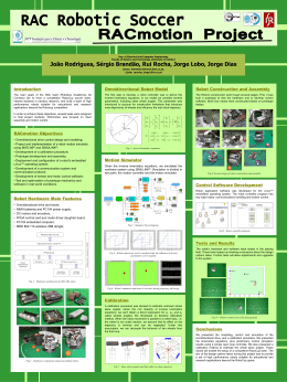
2.2. Robot Head Specifications
The initial specifications for the iCub are quite demanding, both per size (Figure 15)
and weight. The total head weight should not exceed 2 Kg and the size is that of a
2 year old child. The head is 13.6 cm wide, 17cm long and 17.3cm deep. The neck
is 7cm wide and 9cm long. For modularity, we divide the head in the neck and eye
subsystems.
18
Figure 15: Approximate size targeted for the iCUB [Tilley, 2001]
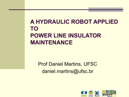
In order to guarantee a good representation of the human movements, the iCub
head contains a total of 6 DOFs: neck pan, tilt and swing, and eye pan
(independent) and tilt (common) as shown in Figure 16. The neck tilt and swing
motion axes intersect the neck pan’s and the eye pan axes intersect the eye tilt’s.
A minimal set of facial expressions were used (implying the smallest possible
number of motors or moving parts) to convey information about the robot’s
emotional status.
Although the human neck has four dof, as the space/weight limitations are very
large the neck was modeled with three degrees of freedom. The atlanto-occipital
flexion/extension was ignored. For most tasks this motion is not necessary, since
orienting the eyes towards a scene point is essentially a two degree of freedom
task. Therefore, the neck still has some redundancy that can be used to avoid
obstacles, occluders or to choose better viewpoints.
The eyes cyclotorsion was ignored because it is not useful for control, and similar
image rotations are easily produced by software. The elevation/depression from
both eyes is always the same in humans, in spite of the existence of independent
muscles. Similarly, a single actuator is used for the robot eyes elevation (tilt). Eye
vergence is ensured by independent motors. Figure 12 shows the final chosen
kinematics, that allows all basic ocular movements.
19
Figure 16: Illustration of the Head degrees of freedom. There is a total of six
degrees of freedom, three for the neck and three for the eye system (facial
expressions are not included)
One of the most critical design steps is that of defining the desired velocities and
accelerations for the various head joints. This will directly impact on the choice of
motors and therefore on size/weight constraints.
Data regarding accelerations, velocities and joint range of the oculomotor system of
human babies are not available, and very few studies exist in the literature of
psychology
or
physiology.
This
section
explains
how
we
obtained
the
anthropomorphic data and specifications for the iCub robot head. Overall, the iCub
dimensions are those of a two-year-old human child, and it is supposed to perform
tasks similar to those performed by human children.
In Table 2 there are two key observations for the iCub head design. First, we used
the smaller range of saccadic speeds as a reference, since (i) these are adult data
and children have significantly smaller speeds and (ii) small amplitude saccades are
close to smooth pursuit movements, which are far more frequent during the robots
normal operation. Secondly, we used the ratio between neck/eye velocity (14% 41%) and acceleration (2% - 4%) as an important design parameter.
Using this information, and hypothesizing a trapezoidal motion profile (Figure 17)
for the eye movements (as axes control boards usually specify), we can compute
the necessary joint acceleration.
The typical motion controller calculates the motion profile trajectory segments
based on the programmed parameter values. The motion controller uses the
desired target position, maximum target velocity, and acceleration values to
20
determine how much time it spends in the three move segments (which include
acceleration, constant velocity, and deceleration).
Figure 17: A typical trapezoidal velocity profile
For the acceleration segment of a typical trapezoidal profile, motion begins from a
stopped position or previous move and follows a prescribed acceleration ramp until
the speed reaches the target velocity for the move.
Motion continues at the target velocity for a prescribed period until the controller
determines that it is time to begin the deceleration segment and slows the motion
to a stop exactly at the desired target position.
The acceleration, α, can be calculated as a function of the total time of the
movement, T, the total range of the movement for each joint, θ, and the ratio
between the total time of the movement and the acceleration/deceleration time
(Ta), f.
From Figure 17, we have:
T = T1 + T2 + T3 and θ = θ1 + θ 2 + θ 3
(1) and (2)
Considering Ta to be acceleration/deceleration time, we get:
Ta = T1 = T2 = f ⋅ T
(3)
In acceleration/deceleration periods, the movement range, θa can be calculated as:
21
θa =
1
1
2
⋅ α ⋅ Ta = ⋅ α ⋅ f 2 ⋅ T 2
2
2
(4)
During the moment where ω is constant, and performing its maximum value, we
have:
ω máx =
θ2
(5)
T2
and
ω máx = α ⋅ Ta =
θ2
T2
(6)
Using this on equation 2, we get:
α=
θ
f ⋅ T ⋅ (1 − f )
2
(7)
For that purpose we only need to define the percentage of time that corresponds to
acceleration/deceleration (e.g. f = 0.2), while the remaining part of the trajectory is
executed at maximum speed. Table 4 shows the final specifications.
The design parameters used indicate that the ratio between neck/eye velocities is
50%, clearly above human data. We further assume that 20% of the time is used
for acceleration (and another 20%) for slowing down. Although the neck swing is
usually slower that other neck DOFs, we considered the ration between neck
swing/{tilt, pan } velocities to be unity. Finally, we postulated that the eye pan
maximum velocity would be 180º/s. The specifications were used for the remaining
part of the design.
Eyes
Neck
pan
tilt
pan
tilt
swing/roll
Range
[º]
Vel Max
[º/s]
90
80
110
90
80
180.0
160.0
90.0
73.6
65.5
Acceleration
full range
ac.[º/s^2]
T [s]
mean vel
1440
0.625
144
1280
0.625
128
295
1.528
72
241
1.528
59
214
1.528
52
Table 4: Computed set of angular speed and acceleration for the various degrees
of freedom of the Robot Cub Head
22
3. Model Development
The development of a humanoid robot within the scope of special research area has
the objective of creating a machine that closely cooperates with humans. This leads
to requirements such as little weight, small moving masses (no potential danger for
persons in case of collision), as well as appearance, motion space, and work
movements after the human model. One reason for the last point is the
requirement for the robot to operate in surroundings designed for humans. Another
aspect is the acceptance by technologically unskilled users, which is likely to be
higher if the robot has a humanoid shape and calculable movements.
A humanoid robot is a highly complex mechatronic system, as the required
functionality can only be achieved by the interplay of mechanical components with
extensive sensor technology, modern actuators and highly developed software.
Successful development of complex mechatronical systems is only possible in close
cooperation of specialists of the concerned fields of mechanics, electronics, and
information technology. Discipline-oriented partial solutions cannot provide or only
with significant delays the desired result.
Fig. 18: Product development process in Robotics
As mentioned in the previous sections, the design concepts of the RobotCub Head
are light, compact, but performable for its working applications, meeting the project
dynamic and kinematics specifications. To realize this robot head, several
distinctive mechanisms were employed, produced in different materials and
actuated by diverse types of actuators. In this section, the details of mechanical
design are introduced.
23
The Mechanical Design of the iCub head is divided in three major subsystems: Neck
Mechanism, Eyes Mechanism and Cover (face) for increased modularity. During the
design process, we used the specifications derived previously and adopted the
following desirable characteristics/criteria:
•
DOFs, range of motion, joint speed and torque according to detailed
specifications,
•
Compactness and weight, to meet all the desired specifications (< 2 Kg),
•
Modularity and simplicity of the structure to facilitate maintenance and
assembly,
•
Self-contained to facilitate integration with the other parts of the robot,
•
Robustness, to resist the efforts suffered during its working period,
•
Use of standard mechanical components.
The following sections describe the various possibilities considered for each
component.
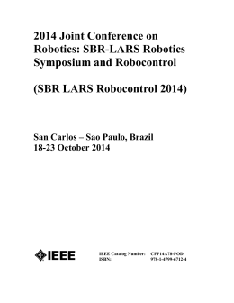
3.1. Neck Mechanism
For the Neck Mechanism, 3 different solutions were considered (Figure 19).
Figure 19: Three alternative solutions for neck mechanism
24
3.1.1. Flexible Neck Solution
Inspired by the flexibility of human neck, one design concept included a flexible
neck, which would work as a spring (represented by the red cylinder), Figure 20,
actuated with 3 cables separated 120º apart, producing a spherical motion of the
head. A final motor could be included on top, assuming the function of atlas, for the
head pan.
Figure 20: Prototype of robot head with spring-based neck.
Flexible-link
robotic
manipulators
have
many
advantages
with
respect
to
conventional rigid robots. These mechanisms are built using lighter and cheaper
materials, which improve the payload to arm weight ratio, thus resulting in an
increase of the speed with lower energy consumption. Moreover these lightweight
arms are more safely operated due to the reduced inertia and compliant structure,
which is very convenient for delicate assembly tasks and interaction with fragile
objects, including human beings.
However, the dynamic analysis and control of flexible-link manipulators is much
more complex than the analysis and control of the equivalent rigid manipulators.
From the modeling standpoint, the challenges are associated with the fact that the
non-linear rigid body motions are now strongly coupled with the distributed effects
of the flexibility along the mechanical structure. This coupling varies with the
system configuration and the load inertia. Besides, the dynamic equations of
flexible
structures
are
infinite
dimensional,
although
for
control
purposes
25
approximated finite order models are usually considered. This truncation, along
with the difficulties in modeling the coupling and nonlinearities of the system, can
be the source of uncertainties in dynamical models, which in turn can lead to poor
or unstable control performance.
Conventional rigid-link manipulators are modeled as a set of nonlinear coupled
ordinary
differential
equations
(ODEs).
However,
in
the
case
of
flexible
manipulators this rigid dynamics is coupled with the distributed effects of the
flexibility along the mechanical structure, which lead to a model expressed in partial
differential equations (PDEs), where both time and spatial derivatives are relevant.
PDEs are not very convenient as models for control design purposes, since they are
theoretically equivalent to infinite-dimensional systems.
To perform the system control of this kind of solution we would have to adapt a
more inconvenient approach. Namely, we would need a sensor structure to apply
feedback onto the system, in order to achieve a close-loop control (Figure 21). So,
an inertial sensor should be included, giving us continuously information about the
head position.
A similar design, using a spring as a neck, was produced by our partners on the
University of Genoa (Figure 22).
Figure 21: Feedback control system
Figure 22: Prototype of robot head with spring-based neck, produced by University
of Genoa
26
Another problem with this design, further than control complexity, is that motors
would have to be placed in the robot chest, jeopardizing the design modularity.
Given that, this solution was discarded.
3.1.2. Parallel Mechanism Solution
To be modular and self-contained, the head structure must support a large number
of mechanical and electrical components. On the other hand, high torque motors
are required to drive the cameras, in particular to achieve the velocity of saccadic
eye movements. So, to satisfy both (conflicting) requirements, an interesting
solution for the robot neck structure is based on a parallel mechanism (Figure 22).
Parallel mechanisms have remarkable characteristics such as high precision, high
load capacity, high rigidity, interior space for cabling and easy solutions for the
inverse kinematics. Also, since all motors are fixed on the base, the inertia of the
moving part is relatively small.
There are several categories of parallel mechanisms, and their classification is made
fundamentally according to their degrees of freedom, motion type and geometrical
architecture [Merlet, 2001]. In our case, since we were trying to reproduce the
movement of a 3 dof rotational neck, the most suitable solutions were on the
special 3 dof orientation mechanisms (Figure 23).
Three dof orientation mechanisms allow three rotations about one point and
represent an interesting alternative to the wrist with three revolute joints having
convergent axes classically used for serial robots.
In order to provide only rotary motions about one point, one can use four
generators. One of them being a passive generator of rotary motion about one
point.
27
Figure 23: Various architectures of three dof orientation mechanisms [Merlet,
2001]
The simplest, and chosen solution, was the 3-UPS architecture (Figure 24), where
each generator active link is composed by an universal joint, a prismatic joint and a
spherical joint.
Figure 24: CAD Model of the Parallel Neck and prototype
28
Because of its complex 3D geometry, the design of the 3-UPS solution is not very
trivial. Therefore, the calculation of the actuator’s stroke, required maximum
velocity and load capacity were made using Kinematic and dynamic simulations.
The kinematic modeling of the 3-UPS architecture, [Gregorio, 2003], [Alici et al.,
2004], [Gregorio, 2004], was made considering it to be composed of a fixed
tetrahedron, a moving tetrahedron and three identical limbs (Figure 25). The
tetrahedrons have equilateral triangular bases of different sizes. The tips of the
tetrahedrons are linked using a spherical joint. The limbs are connected to the
moving tetrahedron base with 2-DOF universal joints and to the fixed tetrahedron
base with spherical joints. A linear actuator controls the leg length, and forms a
prismatic joint. Each universal joint is treated as two revolute joints with axes
perpendicular to each other and intersecting at a point.
Figure 25: Parallel Mechanism Architecture [Alici et al., 2004].
In Figure 23, ui4 is the unit vector along the prismatic joint axis for leg i, ui5 and ui6
are the unit vectors along the axes of the universal joint of leg i. ui7 is the CBi edge
of the moving tetrahedron [Alici et al., 2004].
A coordinate system is chosen for each tetrahedron as shown in Figure 26. Frames
A and B are defined for the base and moving tetrahedrons respectively. Their origin
is placed at the common tip of the tetrahedrons and represents the point around
which the moving tetrahedron rotates.
29
Figure 26: Coordinate systems of the 3-UPS platform.
As seen in Figure 26, the position vectors of points Ai and Bi with respect to frames
A and B respectively, can be written as:
A
[
]
B
ai = aix , aiy ,−ha ,
T
and
[
bi = bix , biy ,−hb
]
T
(8)
The scalar aixy, shown in Figure 26, denotes the distance between the center, O, of
the base triangle of the fixed tetrahedron and anyone of the corners of the base
triangle. The scalar bixy denotes the distance between the center, E, of the base
triangle of the moving tetrahedron and any of the corners of the base triangle. The
parameter ci denotes the difference between aixy and bixy.
Parameter di denotes the length of leg i. The vector di represents the position
vector of the leg i (AiBi) in the base coordinate system:
A
[
d i = d i , xa , d i , ya , d i , za
]
T
(9)
The scalar ha denotes the height of the fixed tetrahedron and is the distance from
point O to point C. The scalar hb denotes the height of the moving tetrahedron and
is the distance from point E to point C. The parameter h represents the total height
of the parallel platform in (0,0,0) orientation and is equal to the sum of ha and hb .
The parameter hab is the ratio between ha and hb.
30
The transformation from the moving frame B to the fixed frame A can be described
by a 3x3 rotation matrix ARB defined by a z-x-z (φ-θ-ψ) Euler rotation. Given that,
in the initial position (0-0-0 rotation) the xa and xb axes coincide, za and zb, and ya
and yb are in opposite directions respectively, the resulting rotation matrix is given
by:
A
⎡cφcψ − sφcθsψ
RB = ⎢⎢ sφcψ + cφcθsψ
⎢⎣
sθsψ
cφsψ + sφcθcψ
sφsψ − cφcθcψ
− sθcψ
− sφsθ ⎤
cφsθ ⎥⎥
− cθ ⎥⎦
(10)
where c represents the cosine and s the sine of the following angle.
For the direct kinematics the leg lengths di and the triangular bases’ geometry are
known. The three orientation angles of the moving platform are determined from
expanding the following three scalar equations:
2
2
2
d i = ai + bi − 2ai bi ,
T
i = 1,2,3
for
(11)
For the inverse kinematics the orientation of the moving platform is known and the
limb lengths, di are calculated from the following three equations:
2
2
d i = ± ai + bi − 2ai bi ,
T
for
i = 1,2,3
(12)
The manipulator Jacobian matrix J relates the end-effector velocities vector v to the
actuated joint velocities vector d& :
J xϖ + J d d& ,
−1
J = J d Jx
(13)
For the 3-UPS platform Jx and Jd are given by:
⎡ (u1,7 × u1, 4 )T ⎤
⎢
⎥
J x = ⎢(u2,7 × u2, 4 )T ⎥
⎢ (u3,7 × u3, 4 )T ⎥
⎣
⎦
J d = [I ]
(14)
31
For such a small size neck (9cm x 7cm), we had to design our own linear actuators,
with the mechanism moved by three Linear Ball Screw Actuators.
Comparing with other solutions, this type of actuators offers a good compromise
between size, controllability and load capacity. The mechanical structure of these
components is shown in Figure 27.
Figure 27: Ball Screw Linear actuator
This Linear Actuators have a Thomson Saginaw Configuration, which consists of a
DC motor mounted parallel to a ballscrew system through a reduction gear
assembly in such a way that the rotational motion produced by the DC motor
produces the linear movement of the ballscrew.
So, in order to calculate the design parameters of the linear actuators (the
maximum stroke, the maximum velocity and the load capacity of the actuators)
several
kinematic
and
dynamic
simulations
were
made,
in
Matlab,
and
CosmosWorks, Figures 28 and 29.
32
Figure 28: Kinematic Simulations, using Matlab
Figure 29: Dynamic Simulations, using CosmosWorks. The three different graphics
show the evolution of the forces required in each actuator of the mechanism in
maximum acceleration simulation.
The most considerable disadvantage for this concept is that it is very difficult to
avoid the interference between the various parts, for such large movements,
decreasing significantly its workspace. Given that, this solution was also discarded.
33
3.1.3. Serial Mechanism Solution
The third tested solution was of a serial manipulator with three degrees of freedom,
placed in a configuration that best represents human neck movements. In spite of
its simplicity, the mechanism is very robust, easy to control and highly performing,
meeting all the specifications. For these reasons, this was the final choice adopted
for the iCub head neck.
Figure 30: CAD Model of Serial Mechanism
As can be seen in Figure 30, the neck mechanism is a serial manipulator composed
by 3 revolution joints. The tilt joint is the first one, followed by the swing joint and
the pan joint, whose axis of rotation crosses the other two. To realize them, a
compact design for mechanism that is composed by 3 different actuation modules,
for the 3 different joints was employed. Figure 31 shows an element of compact
34
design and the drive system mechanism, used in all joint of the neck. Its
mechanism is formed from DC motor (together with a respective gearbox and
encoder), rotational bushings, mechanical stop, and an absolute position sensor.
This setup can be considered very robust since the axial and radial external loads
are not transmitted to the actuator’s shaft.
Figure 31: CAD Model of the Tilt Actuation Module of the Neck Mechanism
One major requirement of this system is the resilience to damage of the robot units
since learning (cognition, understanding, and behavior) of the robot will potentially
involve many “falls” and “accidents” experienced by any child learning to cope with
the world. This may be particularly critical for the delicate head and neck
mechanisms.
To overcome this problem, the pan joint in the serial neck mechanism uses an
overload clutch system (Figure 32) since its actuator’s gearbox is the weakest one
and would not resist to an impact situation. The Overload Clutch System is
essentially composed by a driven component, which is fixed to the driven part of
the mechanism, a nut, a belleville spring and a clamp device, fixed to the motor
shaft. When the belleville spring is compressed by the nut, the driven component is
35
smashed against the clamp device, producing enough friction to transmit the
movement of the joint. In an overload situation, this friction will not be enough and
the driven component will slide, protecting the motor gearbox from the impact.
The overload clutch system increases the robustness of the mechanism, giving it
the possibility to fall on the floor and suffer different kind of impacts and efforts
during its interaction with the external world.
Figure 32: Clutch based overload protection system.
The belleville springs are shaped like a coned disk and especially useful where large
forces are desired for small spring deflections.
Two of the critical parameters affecting the Belleville spring are the diameter ratio,
Rd, and the height-to-thickness ratio h/t (Figure 33).
Rd =
D0
D1
(15)
Figure 33: Tipical Belleville Spring.
36
From Figure 34 the behaviour of a Belleville spring is highly nonlinear and varies
considerably with the change in h/t. For low h/t values the spring acts almost
linearly, whereas large h/t values lead to highly nonlinear behaviour. The forcedeflection curves for Belleville springs are given by
P=
4 Eδ
⎡
δ⎞
⎛
3⎤
(
h
)
h
t
t
δ
+
−
−
⎟
⎜
⎥
⎢
2⎠
K 1 D0 (1 − ν 2 ) ⎣
⎝
⎦
2
(16)
where E is the elastic modulus, δ is the deflection from the unloaded state, D0 is the
coil outside diameter, ν is Poisson’s ratio for the material, h is the spring height,
and t is the spring thickness. The factor K1 is given by
K1 =
6 ⎡ ( Rd − 1) 2 ⎤
⎢
⎥
π ln Rd ⎣ Rd 2 ⎦
(17)
Figure 34: Force-deflection of Belleville Spring.
Considering TM (Nm)to be the maximum allowable torque that the gearbox of the
actuator can support, the desired P is
P=
TM
πμri (r0 2 − ri 2 )
(18)
where μ is the friction coefficient of the spring’s material.
Using equations (18), (17) and (16) the optimal deflection of the Belleville Spring,
from the unloaded state, can be calculated (Table 5).
37
TM (mNm)
600
μ
0.2
D0 (mm)
18
D1 (mm)
8.4
t (mm)
0.0010
h (mm)
0.0014
Rd
2.25
K1
0.73
P (mN)
4515
δ (mm)
0.0006
Table 5: Calculation of the ptimal deflection of the Belleville Spring for clutch
system
As the thread pitch of the M8 nut, used in the clutch system, is 1.25 mm, it should
be rotated 180º to guarantee the correct deflection, δ, of the Belleville Spring.
3.2. Eyes Mechanism
The eyes cyclotorsion was ignored because it is not useful for control, and similar
image rotations are easily produced by software. The elevation/depression from
both eyes is always the same in humans, in spite of the existence of independent
muscles. Similarly, a single actuator is used for the robot eyes elevation (tilt). Eye
vergence is ensured by independent motors. Figure 35 shows the final chosen
kinematics, that allows all basic ocular movements.
The pan movement is driven by a belt system, with the motor behind the eye ball
(Figure 36). The eyes (common) tilt movement is actuated by a belt system placed
in the middle of the two eyes. Each belt system has a tension adjustment
mechanism.
38
Figure 35: Eyes mechanism
Figure 36: Single Eye Mechanism
39
3.3 Actuators Selection
The selection of actuator and reduction ratio is an important issue in the design of a
humanoid robot. The reason is that the more powerful actuators are selected, the
heavier the humanoid is constructed, and therefore, the more powerful actuators
are required. To optimize the selection of actuators and reduction ratios, iterations
of mechanical design are necessary.
Several analytic calculations and dynamic simulations were carried out on the neck
and head motions including the six specified degrees of freedom, defined in Section
2.2. The results of calculations were obtained from simulating the robot head
moving its 6 joints in the most critical movements, with the maximum acceleration
and gravity forces.
These results gave us the guidelines to decide hardware specifications such as
actuators, reduction ratios of gears and pulleys and other kind of mechanical
components. By comparing data present on standard actuators catalog and that
obtained from the calculations and simulations, we finally decided the hardware
specifications on motors, gear boxes and encoders.
Since electrical motor control is relatively easy and has been widely studied, it was
decided by the RoboCub Consortium to use it for the icub actuation. So, as the DC
motors are fairly compact, we decided to use Faulhaber DC Micromotors, connected
with Faulhaber and Gysin Planetary Gearheads and Faulhaber Magnetic Encoders
(Figure 37).
Figure 37: Faulhaber DC Micromotors, Gearheads and Magnetic Encoders
40
The joints of the Neck and Eyes Mechanisms can be represented by the following
way:
Figure 38: Joints representation
, where:
-
T is the torque of the motor, that we want to calculate,
-
α is the maximum acceleration for each joint, calculated in Section 2.2,
-
θ is the maximum rotation of the joint from the vertical position. In the
calculation the worst-case scenario of the value was changed to 90 degrees,
since it should be very frequent, e.g. when the robot is crawling.
-
d is the distance of the center of gravity of the rotating part to the axis of
rotation of each joint. The exact value is given by SolidWorks,
-
Fg is the weight of the rotating part of each joint, whose value is given by
SolidWorks,
-
I is the moment of inertia of the rotating part of each joint about the
rotating axis. The exact value is given by SolidWorks,
So, for a general situation, we have:
T = Fg ⋅ d + I ⋅ α
(19)
The two members of the right side part of the equation correspond, respectively, to
the gravity and inertia part of the required torque. The calculations showed us that
41
the gravity part is much more relevant than the inertia one.
Computing the previous formula for the 5 different joints of the mechanisms, we
got the values presented in Table 6.
Joint
Pan
Neck
Tilt
Swing
Pan
Eyes
Tilt
d (m)
m (Kg)
Fg (N)
I (Kg.m2)
θ (º)
a (rad/s2)
0.022
1.1
10.78
0.003
90
5.1
0.088
1.34
13.13
0.014
90
4.2
0.064
1.24
12.15
0.007
90
3.7
0.007
0.036
0.35
6.50E-06
90
25.1
0.012
0.13
1.27
8.60E-05
90
22.3
Table 6: Torque calculation for mechanism joints
T (mNm)
252.6
1214.6
803.9
2.6
17.2
After getting these values of the required torques for the different joints, the
actuators (motor + gearbox + encoder) were chosen from the catalog and are
presented in Table 7.
Motor
Joint
Company
Neck
Eyes
Gearhead
Ref.
Ref.
Encoder
GR
Ref
Tilt
Faulhaber
1724024SR
Gysin GPL 22
343
IE2-512
Swing
Faulhaber
2224024SR
Gysin GPL 22
245
IE2-512
Pan
Faulhaber
1717024SR
Faulhaber 16/7
246
IE2-512
Tilt
Faulhaber
1319024SR
Faulhaber 14/1
246
IE2-400
Pan
Faulhaber
1319024SR
Faulhaber 14/1
66
IE2-400
Table 7: Actuator references for the 3 different joints of the neck mechanism
The final characteristics of the actuators are presented in Table 8:
Final Caracteristics
Joint
Neck
Eyes
Torque
Vmax
A.max
T.avail
Backlash
Resolution
(Nm)
(º/s)
(º/s^2)
(Nm)
(º)
(º)
Tilt
1.215
105
285
1.225
≤0,5
0.002
Swing
0.804
147
1922
1.041
≤0,5
0.003
Pan
0.250
122
1115
0.295
≤1
0.003
Tilt
0.017
189
180000
0.186
≤1
0.006
Pan
0.003
455
658000
0.077
≤1
0.014
Table 8: Actuator Final Characteristics for the 3 different
joints of the neck mechanism
Comparing these final values with the specified ones, presented in section 2.2, it
can be seen that the maximum velocities and accelerations not only satisfy the
specified ones but exceed them, approaching the maximum values of an adult
human.
42
3.4. Eyelid Mechanism
The concept of this eyelid mechanism was inspired in a classic mechanical linkage
mechanism: the Four Bar Mechanism, Figure 39. It consists of 4 rigid bodies (called
bars or links), each attached to another two, by single joints or pivots to form a
closed loop. Planar four-bar linkages perform a wide variety of motions with a few
simple parts. They are also popular due to ease of calculations, compared to more
complex mechanisms.
Figure 39: Typical configuration of a Four Bar Mechanism
As can shown in Figure 40, the Eyelid Mechanism is composed by two Four Bar
Mechanisms working in parallel, having just 1 DOF - an upper one, for the upper
eyelid system, and another for the lower eyelid system. The length of the different
links was optimized to transform the servomotor input (witch is the same for both
eyelids) in a different output, altering the motion, velocity and acceleration of the
upper and the lower eyelids.
Figure 40: The Eyelid Mechanism composed by the two parallel Four Bar
Mechanisms (the upper eyelid system in blue and the lower eyelid system in
yellow)
43
Figure 41: Different views of the Eyelid Mechanism
To guarantee the spherical concentricity of the eyes and the eyelids, and to
increase the compactness of the mechanism, the eyelids system shares the shaft of
rotation with the eyes system.
The left and right eyelids are fixed by the two yellow aluminium components shown
in Figure 41.
In order to allow little improvements of the eyelids position, the upper and the
lower link’s length can be changed by an adjustment system, Figure 42.
Figure 42: Link Adjustment System
44
Apart from the eyelids, all mechanical components of the system are aluminium
machined parts.
Due to its complex geometry, the eyelid components (Figure 43) are produced by
an SLS process, the same used for the production of the Head Cover. They are
glued to the mechanism by cyanoacrylate glue and its correct position is
guaranteed by two positioning pins, which are part of the eyelid components.
Figure 43: Eyelid geometry
In the actuation of this mechanism, we are using a Futaba S3111 (Figure 44)
servomotor; witch is a cheap, small, light and relatively high torque solution.
Specifications:
Length: 21.8mm
Width: 11mm
Height: 19.8mm
Weight: 6.6g
Speed: 12 sec/60°
Torque: 60 mNm
Figure 44: Futaba servomotor (http://www.futabarc.com/servos/servos.html)
In the configuration of the mechanism, the servo has a range of movement of 75º,
from the closed eyelid position to a maximum opened eyelid position.
45
3.5. Material Selection
The data given in Figure 45 allow a preliminary assessment to be made of several
materials of interest, showing the strength of several materials plotted against
density.
Figure 45: Strength of several materials plotted against Density
The high density of steel- nearly 3 times that of Aluminium- would seem to make it
a poor prospect for use in robotic systems, and yet it has been used quite
extensively. That is especially because of its high strength and production facilities.
On this specific design, excluding the screws, washers, nuts, pins and shafts, steel
(303SS) was used in very thin parts and in small threaded components.
Figure 46: Some steel components of the head mechanism
Aluminium alloys are still the major materials for robotic systems construction, and
seem likely to remain so for the foreseeable future, although the proportion of total
take-off weight which they represent will no doubt progressively decrease due
mainly to competition from composites. As shown in Figure 45, in terms of
46
strength/density ratio, aluminium alloys can be superior to steel.
Another advantage from steel is the fact that aluminium alloys are corrosion
resistant.
So having in mind all this information, the majority of the components of the
system were produced in aluminium (Al 7075-T6), especially the bigger and more
complex structural parts.
Figure 47: Some aluminum components of the head mechanism
Plastics can offer improved specific properties compared with steel, thereby saving
weight (nearly 6 times less). They can resist corrosion, can have a high quality
surface finish and can be much more easily machined. However, it is not
recommended to thread them and they can not guarantee a high level of geometric
tolerances. So, plastic components were only used in big non structural, and non
threaded, parts, like the eye balls of the robot.
Figure 48: A plastic component of the head mechanism
3.6. Assembly
As an open physical platform for embodied research, that can be used by the
research community from different types of science fields (like physiology, cognitive
robotics and perceptual science), the iCub mechatronics system cannot be very
complex. So, in order to guarantee easy assembly and maintenance procedures,
the mechanical system architecture is also completely modular, in such a way that
47
we can remove and replace a certain module, without having to disassemble the
entire structure. Figures 49 and 50 show the different modules of the head, and the
integration with electronics.
Figure 49: Modular Architecture of the System
Figure 50: Exploded View of the head mechanism
48
3.7. Sensors and Electronics
To allow the robot to interact with other people and to have all desired behavior
several sensors were applied.
For vision, the main sensory modality, two DragonFly cameras [www.ptgrey.com]
with VGA resolution and 30 fps speed. These cameras are very easy to integrate
because the CCD sensor is mounted on a remote head, connected to the electronics
with a flexible cable. In this way, the sensor head is mounted in the ocular globe,
while the electronics are fixed to a non-moving part of the eye-system.
Figure 51: DragonFly Camera (sensor head and
electronics connected by a flexible cable)
The inertial sensor is very important to have the vestibuloocular reflex and to
detect the overall posture of the body. We have selected the from MTi sensor, from
Xsens Technologies B.V. It is a miniature, gyro-enhanced Attitude and Heading
Reference System. Its internal low-power signal processor provides drift-free 3D
orientation as well as calibrated 3D acceleration, 3D rate of turn (rate gyro) and 3D
earth-magnetic field data.
The MTi uses 3 rate gyros to track rapidly changing orientations in 3D and it
measures the directions of gravity and magnetic north to provide a stable
reference. The systems real-time algorithm fuses the sensor information to
calculate accurate 3D orientation, with a highly dynamic response and stable over
time.
49
Figure 52: MTi sensor
All motor control boards will be specially designed to fit in the size constraints of
the robot. They are all integrated in the head and connect to the remote computer
with CANbus.
Figure 53: Motor control boards
To measure the head position (kinesthetic information), the motors have magnetic
encoders, for calibration purposes absolute position sensors were applied to each
neck
joint.
GMW
Associates
(www.gmw.com)
has
available
a
sensor, the
GMW360ASM, capable of 360º angular sensing with linear output. It is a cylindrical
package with 12.7mm diameter and 5 mm thick. It is constituted by two hall
sensors in quadrature and a microprocessor that computes the direction of the
magnetic field based on the quadrature measurements. The GMW360ASM provides
an Analog and PWM output signal which is proportional to the mechanical angle of a
magnet with a resolution of 0.75 degrees. In addition to the absolute angle position
outputs, the GMW360ASM detects when the field strength of the magnet is too low
and provides a discrete “Magnet Out of Range” signal. The electrical “Zero Angle”
position can be set to correlate to any mechanical position within 360 degrees. This
is accomplished by momentarily connecting the Analog Output pin to the +5 Volt
supply and applying power.
50
Figure 54: Absolute position sensor
The electrical output of the module for the zero angle position can be set to match
any mechanical position of the magnet within the 360 degree rotation. This feature
eliminates the need to mechanically align the position of the sensor output to the
mechanical position of the rotating target. The zero angle output is 2.5V for the
Analog Output and 50% Duty Cycle for the PWM output. The Zero Angle set
function is initiated by providing a momentary connection between the Analog
Output pin and the 5V supply prior to applying power to the module. Once power is
on for more than 100 ms, the momentary connection is removed and a 100 ms
“Zero Angle” calculation is initiated. At the end of the 100 ms time, the
GMW360ASM is operational and the Analog Output will be set to 2.5V and the PWM
output will be set to 50% Duty Cycle. The Zero Angle set point is permanently
stored into fl ash memory and remains there until a new Zero Angle command is
initiated. The maximum number of changes to this set point is 50000.
Figure 55: GMW360ASM Output characteristics
51
3.6 External Cover
Since this robot is designed to be engaged in social interaction, one of the main
concerns in the design is the understanding of which facial features dimensions
contribute more to the communication with humans. This research is important for
the fields of human-computer interaction and the impact of design on this field has
to be well understood.
There are several studies [DiSalvo et al., 1993], [Takeuchi et al., 1995] that show
that the presence of certain features, the general dimensions of the head, and the
number of facial features greatly influence the perception of humanness in robot
heads. Some robots are much more successful in the portrayal of humanness than
others. This success is due, at least in part, to the design of the robot’s head.
Mashiro Mori developed a theory of The Uncanny Valley (Figure 56), which states
that as a robot increases in humanness there is a point where the robot is not
100% similar to humans but the balance between humanness and machine-like is
uncomfortable, and so, there is a reasonable degree of familiarity that should be
achieved and maintained in humanoid robots [Reichard, 1978].
Figure 56: Mori’s The Uncanny Valley [Reichard, 1978].
The external cover must also ensure the protection of head mechanisms, absorbing
external efforts, suffered by the robot during operation. Figure 57 shows the first
prototype of the iCub face, where a “toy-like” concept was selected for the design.
52
Figure 57: Preliminary Design of the iCub external cover (made by AlmaDesign).
In order to accurately estimate the location of a sound source in both the horizontal
and vertical plane, two human-like ears of simple spiral-shaped, with a microphone
on the center, were designed and added to the final version of the iCub external
cover (Figure 58).
Figure 58: Final Design of the iCub external cover
53
54
4. Performance
Several tests were made to evaluate the functional use of the designed head. Every
joint was tested, in the worst case scenario, to verify that velocity and acceleration
specification where met. Several other demos/tests were created to verify the
coordination between the sensors and actuators in the system.
Figure 59: Final prototype of the iCub head with face
1) Mechanical performances - In order to simulate the hardest working situations of
the mechanism, its base was fixed in a vertical position, as shown on Figure 60.
Figure 60: Movements made during the mechanical tests
The weight of the head components was measured before the realization of the
55
mechanical tests. The values are shown on Table 9.
Component's Weight (g)
Cover
257
Mechanism
1104
Extra Payload (Full)
340
Total
1701
Table 9: Weight measurement
The test of each dof was made using the following procedure:
Static Test
1. The head was fixed on its homing position, with zero velocity, full load
(payload=340g), for a short period of time (t= 5s);
Dynamic Test
2. The head was moved, with its maximum velocity, along its total range of
movement, with full load, for a short period of time;
Endurance Test
3. The head was moved, with its maximum velocity, along its total range of
movement, with full load, for 30 min, verifying the temperature of the
actuator;
Joint
Tilt
Swing
Pan
Payload (g)
340
340
340
Vel
Test Period
Real Range of
(rad/s)
(s)
Movement (º)
0
5
1.3
5
1.3
1800
0
5
1.2
5
0.1
5
0
5
1.6
5
1.6
1800
Obs
+40; -50
+40; -40
+55; -55
Table 10: Different tests Summary
After these experimental tests (Table 10), we could conclude that, the neck
actuators were able to move the head, during 30 min, with full load.
56
2) Object tracking- An object moving in front of the system is considered to be
successfully tracked if it is near the center of both images. Since this is a 3 dof task
and the robot has 6 dof, some extra criteria should be used to control all dof. The
eye's 3 dof are directly controlled with a visual servoing mechanism, having the
image positions of the object as feedback. The neck is then controlled in order to
maintain the eyes as far as possible for their joint limits. This choice is motivated
by biological behavior. The raionale for having the eyes in a confortable position is
that they will be readily available to track the object in any direction even if it
moves very fast (Figure 61).
Figure 61: Light tracking test
3) Balancing - The inertial sensor provides a reliable measure of the orientation of
the head and also the angular velocities. This information can be used to keep the
head always in a upright position. The inclination information controls directly the
first 2 dof of the neck. The angular velocity is used to create an artificial vestibular
reflex that in presence of a fast motion keeps the eyes looking in the same direction
(Figure 62).
Figure 62: Balancing test
57
4) Sound localization - Using information about the time difference, sound energy
level and spectral power at some special frequencies, it is possible to localize sound
sources with the iCub head. This algorithm is very reliable for the horizontal plane
and can be used either with a closed or an open loop controller (Figure 63).
Figure 63: Sound localization test
58
5. Conclusions/ Future Work
We presented the design for a robot head of a small size humanoid robot. This
humanoid robot - the iCub - is meant to be used as a research tool for human
cognition and publicly distributed worldwide. The iCub neck has 3 dof and the eyes
3 dof, the more complex mechanism for similarly sized robots, where the eyes are
usually fixed.
The specifications were derived from human anatomical and behavioral data. As
some of these data are not available (and even less data can be found for children),
extra assumptions had to be made. We referred to typical tasks the robot should do
and the ratio between neck and eyes velocities/acceleration in humans. The final
kinematic has three dof for the neck. For the eyes, three degrees of freedom
(independent vergence, common tilt) were considered. Other movements like
cyclotorsion can be dealt with at the camera level.
A first solution for the neck was a spring mechanism mimicking the human
anatomy. It has good kinematic capabilities but low repeatability and precision, due
to the spring.
A very small 3 dof parallel actuator was proposed as our second design. It is very
compact and delivers high torque. Due to extremely reduced size, a ball screw
linear actuator was designed. It meets all the specifications, except the desired
range of motion. Although this could be a very attractive solution if we could afford
using a 20% bigger neck, self interference of the mechanical parts precluded its use
at the current stage.
The design that met all the specifications was a serial mechanism. It has a clutch
system to overdrive protection. All motors are similar and the assembly is modular.
As can be seen in Table 11, the dynamic performance of the mechanism not only
satisfy the specified values, presented in section 2.2, but exceed them, approaching
the maximum values of an adult human.
59
Torque (Nm)
Joint
Neck
Eyes
Specified
Final
Vmax (º/s)
Increase
(%)
Specified
Final
Amax (º/s^2)
Increase
(%)
Specified
Final
Increase
(%)
Tilt
1.215
1.225
1
73.6
105
43
241
285
18
Swing
0.804
1.041
29
65.5
147
124
214
1922
797
Pan
0.250
0.295
18
90.0
122
36
295
1115
279
Tilt
0.017
0.186
994
160.0
189
18
1280
180000
13963
Pan
0.003
0.077
2467
180.0
455
153
1440
658000
45694
Table 11: Specified vs. Final dynamic performance of the mechanism
The lightweight eye system has three dofs, consisting of independent eye pan and a
common tilt. The head is equipped with additional sensors, like an inertial sensor
for the vestibular system, kinesthetic information from encoders, absolute position
sensors in the neck and embedded controllers.
A first prototype of the iCub face was designed and built. The head has been
mounted and tracking experiments were done to assess the performance of the
mechanism that is quite encouraging.
As future work, some improvements can be done.
An important upgrade of this robotic head design could be the use of Harmonic
Drive gear boxes (Figure 64) instead of planetary gear heads, since they have
operating principles and construction processes that maximize output torque and
minimize size and weight, offering advantages such as high reduction ratios in a
single stage, zero backlash, and high precision that cannot be equaled by planetary
gear trains.
Figure 64: Harmonic Drive components
60
A re-formulation of the actuation modules could be conducted to a more efficient
cable routing along the serial mechanism of the neck. This could have been
achieved if the actuation modules had had enough space inside allowing the cable
to flow near the center of rotation of the different joints.
Nine units of this head mechanism have already been reproduced in different
countries and the iCub final mechanical design will be freely available to
researchers worldwide, and released under General Public License (GPL) www.robotcub.org.
61
62
6. References
[Alici et al., 2004] Gursel Alici and Bijan Shirinzadeh. Topology optimisation and
singularity analysis of a 3-SPS parallel manipulator with a passive constraining
spherical joint. Mechanism and Machine Theory, 39:215–235, 2004.
[Beira et al, 2005] Ricardo Beira, Manuel Lopes, Miguel Praça, José Santos-Victor,
Alexandre Bernardino, Giorgio Metta, Francesco Becchi, Roque Saltarén, Design
of the Robot-Cub (iCub) Head, ICRA - IEEE International Conference on
Robotics and Automation, Orlando, USA, 2006
[Geppert, 2001] L. Geppert. Qrio, the robot that could. IEEE Spectrum, 41(5):34–
37, May 2004.
[DiSalvo et al., 1993] Carl F. DiSalvo, Francine Gemperle, Jodi Forlizzi, Sara Kiesler,
All Robots Are Not Created Equal: The Design and Perception of Humanoid
Robot Heads. In Proceedings of INTERCHI ‘93, (Amsterdam, the Netherlands,
1993), ACM Press: New York, 187-193.
[Gregorio, 2003] Raffaele Di Gregorio. Kinematics of the 3-UPU wrist. Mechanism
and Machine Theory, 28:253–263, 2003.
[Gregorio, 2004]
Raffaele Di Gregorio. Statics and singularity loci of the 3-UPU
wrist. IEEE Transactions on Robotics, 20(4), 2004.
[Hirose et al., 2001] M. Hirose, Y. Haikawa, T. Takenaka, and K. Hirai.
Development of humanoid robot ASIMO. In Workshop on Exploration towards
Humanoid Robot Applications at IROS, Hawaii, USA, 2001.
[Laananen, 1999] D. Laananen. Computer simulation of an aircraft seat and
occupant in a crash environment. Program som-la/som-ta user manual, US
Department of Transportation, Federal Aviation Administration, 1999.
[Lopes et al., 2004] Manuel Lopes, Ricardo Beira, Miguel Praça, José Santos-Victor,
An anthropomorphic robot torso for imitation: design and experiments, IROS IEEE/RSJ International Conference on Intelligent Robots and Systems, Sendai,
Japan, 2004
63
[Merlet, 2001] Merlet, J., Parallel Robots. Kluwer Academic Publishers, 2001
[Netter, 1998] Frank Netter. Atlas of Human Anatomy. third edition, Learning
Systems
[Panero et al., 1979] Julius Panero and Martin Zelnik. Human Dimension and
Interior Space: A Source Book of Design Reference Standards,. Watson-Guptill
Pubs, 1979.
[Reichard, 1978] Reichard,J. Robots: Fact, Fiction, and Prediction. Penguin Books,
1978.
[Sandini et al., 2004] Giulio Sandini, Giorgio Metta, and David Vernon. Robotcub:
An open framework for research in embodied cognition. International Journal of
Humanoid Robotics, 8(2), November 2004.
[Silva, 2003] Miguel Silva. Human Motion Analysis Using Multibody Dynamics and
Optimization Tools. PhD thesis, Instituto Superior Técnico, Lisboa, Portugal,
2003.
[Takeuchi et al., 1995] Takeuchi, A. and Naito, T., Situated Facial displays:
Towards Social interaction. In Proceedings of Human Factors in Computing
Systems ‘95, (1995), ACM Press: New York, 450-455.
[Tilley, 2001] Alvin R. Tilley. The Measure of Man and Woman: Human Factors in
Design. Henry Dreyfuss, 2001.
[Yamasaki et al., 2000] F. Yamasaki, T. Miyashita, T. Matsui, and H. Kitano. PINO
the humanoid: A basic architecture. In Proc. of The Fourth International
Workshop on RoboCup, Melbourne, Australia, August 2000.
[Zangemeister et al., 1981] Zangemeister and Stark. Active head rotations and
eye-head coordination. Ann N Y Acad Sci, 374:540–59, 1981.
[Zatsiorsky, 1997] Vladimir Zatsiorsky. Kinematics of Human Motion. Human
Kinetics Europe Ltd, 1997.
64
Baixar