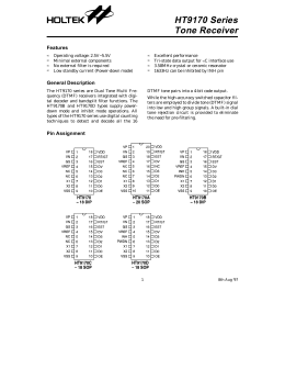
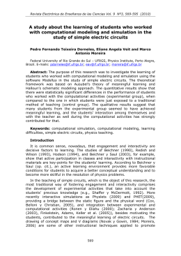
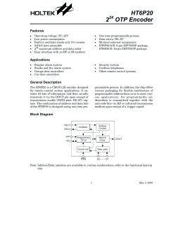
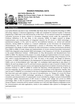
A 2.4GHz CMOS Integer-N Phase-Locked Loop
Vítor Fialho†¥, João Vaz ¥
†
Instituto Superior de Engenharia de Lisboa, Rua Conselheiro Emídio Navarro 1, 1959-0071 Lisboa, Portugal
Phone +351-218317000, Fax +351-218317000, email: [email protected]
¥
Instituto de Telecomunicações, Av. Rovisco Pais 1, 1049-001 Lisboa, Portugal
Phone: +351-218418388, Fax: +351-218418472, e-mail: [email protected]
Abstract 1— This paper presents the study, design and
experimental characterization of a 2.4GHz Integer-N phaselocked loop. Several building blocks are studied, with more
emphasis on the voltage controlled oscillator and frequency
divider. Three circuits were tested, the isolated oscillator, the
oscillator loaded with the frequency divider and the phaselocked loop. All the circuits were designed using the Austria
Micro Systems CMOS 0.35µm 2P4M technology. The voltage
supply is 2.6V. The circuits were tested using chip-on-board
technique.
I. INTRODUCTION
With the Global System for Mobile Communications
(GSM) and more recently with the Wireless Local Area
Network (WLAN), the wireless communications at 2.4GHz
and 5.2GHz have a big market slice comparing with the cable
communications. The high working frequency demands that
the project of these integrated circuits is made in short
channel technologies, such as, the Complementary MetalOxide Semiconductor (CMOS) and Bipolar CMOS
(BiCMOS).
Therefore, during the project it’s mandatory to establish
direct relations between concepts like Signal-to-Noise Ratio
(SNR), Bit Error Rate (BER), Error Vector Magnitude
(EVM) and the electrical parameters of the several devices
that compose the circuits to improve phase noise, power and
consumption [1].
The synthesizer has a major role in transceiver systems
because it offers a stable signal whose frequency is integer or
fractional related to a reference value. Because the
synthesizer frequency can be changed, it is possible to select
the wanted channel [1] [2].
This paper presents the design of an integer-N phase-locked
loop (PLL) for 2.4GHz applications implemented with the
0.35µm 2P4M CMOS technology from Austria Micro
Systems (AMS). The N has a fixed value of 32.
Section II presents the project of the building blocks used
on the PLL such as the Voltage Controlled Oscillator (VCO),
the frequency divider and the charge pump. In section III
measurement results are shown and finally in section IV some
conclusions are made.
The financial support for integrated circuits fabrication was made by
IT/LA/P305 project.
II. PLL BUILDING BLOCKS
The PLL reported in this paper has the topology shown in
Figure 1.
f REF
φREF
PFD
Loop
Filter
Charge
Pump
VCO
fo
f DIV
φDIV
%N
Fig. 1. Integer-N PLL topology.
These blocks are a VCO, a modulus N divider, a PhaseFrequency Detector (PFD), a charge pump and a loop filter.
The output frequency is given by (1)
f o = N ⋅ f REF
(1)
were fREF is the reference frequency. The N factor is the
division ratio which, in this particular circuit, has a fixed
value of 32. Therefore for a 2.4GHz output frequency, fREF is
75MHz. Following the design of the PLL building blocks will
be described.
A. The 2.4GHz LC VCO
The VCO design is made with the technique described in
[3], where a generic VCO circuit is decomposed in a passive
circuit (LC tank) and an active circuit (cross coupled
differential pair). At 2.4GHz the chosen tank inductor has a
5nH value, 18Ω series resistance, and a 4.17 quality factor
value [1].
The dimensions of the MOS varactors (M1, M2) are
obtained by simulation of the LC tank circuit and taking into
account an excess capacitance from the active circuit. This
excess capacitance was chosen to be equal to 300fF.
The cross-coupled transistors (M3, M4) can compensate the
resistive losses of the LC tank circuit, because its equivalent
resistance is negative [1] [2] [4]. Their dimensions were
obtained keeping in mind that their equivalent capacitance
must be 300fF at 2.4GHz. So, the width for the MOS devices
was 200µm [1]. For these dimensions, the minimum bias
current for the on-set of the oscillations obtained by
simulation was 500µA [1].
Vout -
VDD
VDD
Vcont
L
VDD
Vout +
VDD
VDD
L
MB2
MB1
LO_buffLO1-
LO_buff+
LO1+
R
R
R
M1
R
R
R
M2
VDD
VDD
M3
M1
M4
IBIAS
MB4
M2
M7
M3
MB3
buff-
M8
M9
M4
M10
buff+
R
R
M5
M6
M11
M12
IBIAS
M5
IBIAS
M6
Fig. 2. LC VCO schematic.
MB1
MB2
M14
Vin +
2.6
2.55
Fig. 4. SCL frequency divider by 2.
The drain resistance allows adjusting the DC value of the
output signal, and at the same time with M1 to M4 and M7 to
M10 dimensions, obtain the correct value for the division. The
bias current (IBIAS ) is 1mA.
2.45
2.4
2.35
Measured
Simulated
After connecting the VCO with the frequency divider, the
whole circuit simulation gives the results presented in figure
5. This way it is possible to see if the divider is working
properly [1].
2.2
2.15
1.4
1.6
1.8
2
2.2
2.4
2.6
2.8
Vcont [V]
Fig. 3. Simulated and measured output frequency.
Figure 2 presents the LC VCO schematic. The buffers that
allow connecting this circuit to a spectrum analyzer and to the
frequency divider are represented in shadowed. The source
resistance value (R) that composes the source followers (MB1
to MB4) is 500Ω. These values establish a compromise
between consumption, load effect and output power [1].
Comparisons between simulation and experimental results
are shown in figure 3 for the VCO output frequency. The
VCO is tunable in the required band, but the experimental
gain (KVCO) is lower than the simulated one, 558MHz/V and
1.58GHz/V, respectively. This difference is justified as
explained in [5].
The output power is -25.12dBm and the phase noise
-75.09dBc/Hz@100kHz and -115dBc/Hz@10MHz, for a
2.4GHz output frequency.
B. Frequency Divider
The frequency divider is based on the Source-Coupled
Logic (SCL) topology. This divider does a division by 2 of
the VCO output frequency, and uses two type D
flip-flops.
The circuit is shown in figure 4 [1].
Frequency [GHZ]
2.3
2.25
2.5
2
VCO
Divider
1.5
1
1.6
1.7
1.8
1.9
2
2.1
2.2
2.3
2.4
2.5
2.6
2.3
2.4
2.5
2.6
Vcont [V]
2.005
Division ratio
Frequency [GHZ]
2.5
2.1
Vin -
M13
2
1.995
1.6
1.7
1.8
1.9
2
2.1
2.2
Vcont [V]
Fig. 5. Simulated VCO and divider output
frequencies, and divider ratio.
The ratio error between 2.25GHz and 2.51GHz is less than
0.01% and is due to FFT numerical errors.
As said before the required total divider ratio is 32,
therefore, five of these blocks in cascade were used.
ICP
C. Phase-Frequency Detector
VCONT
A typical logical circuit of a PFD is shown in figure 6 [6].
CZ
CP
1
RZ
D
Q
a(t)
CLK
b(t)
CLK
UP(t)
Fig. 8. Loop filter.
reset
Capacitor CP value is 16pF and CZ is 270pF. The resistor
value is 1.5kΩ. These elements are placed off-chip and their
values were obtained by [1] [9].
reset
DN(t)
Q
D
1
F. PLL
Fig. 6. PFD logic circuit.
This configuration allows comparisons between phase (φa
and φb) and frequency (fa and fb) of the input signals a(t) and
b(t). The flip-flops circuit is based on True Single Phase
Clock (TSPC) topology [7].
Figure 9 shows the VCO control voltage (VCONT) during
PLL locking acquisition. This simulation was obtained for a
reference frequency of 75MHz.
This topology has great advantages such as reduced number
of devices and low consumption. The main disadvantage is
the high sensitivity to small variations of the supply voltage.
D. Charge Pump
The charge-pump circuit is shown in the figure 7 [8]. The
main advantage of this circuit is that it uses only one current
source instead of the typical two. This simplifies the external
bias of the chip. Usually this source value is less than few
hundreds of µA, however in this work 1mA was used due to
the necessary voltage swing that must be applied to the VCO.
The switches are made by MOS transistors M3 and M10 [1]
[8].
Fig. 9. PLL locking acquisition for fREF = 75MHz.
VDD
III. EXPERIMENTAL RESULTS
UP
M1
M2
In this section the experimental results of the PLL are
presented. Figure 10 presents a photo of the chip mounted on
a PCB test-board.
M3
M4
M6
M5
ICP
ICP
M7
M8
DN
M9
M10
Fig. 7. Charge-pump circuit.
E. Loop Filter
In close loop, the PLL is an unstable system. Therefore it is
necessary to introduce an additional zero [1] [2] [4]. So,
besides charge pump capacitor CP, a series capacitor resistor
circuit is introduced, as shown in figure 8.
Fig. 10. Photo of the chip mounted on a PCB test-board.
First, the circuit was tested for a fixed reference frequency.
This way it is possible to visualize the PLL output signal
spectrum and check if the division is correct. Figure 11 shows
the PLL output spectrum at fo=2.4GHz for a reference
frequency fREF=75MHz.
Fig. 11. PLL output spectrum for fREF=75MHz.
It is also possible to measure the lock and the capture bands.
The capture band is 282MHz and the lock band is 323MHz.
The total consumption of this circuit is 34mA from a 2.6V
supply voltage.
Simple output buffers were used which justifies the low
oscillator output power.
IV. CONCLUSIONS
In this paper it was described the working prototype of a
monolithic 2.4GHz Integer-N PLL, implemented on a CMOS
0.35µm 2P4M technology. The circuit area including pads is
995µm x 545µm. The loop filter defines the capture and lock
bands, because in CZ and RZ absence, these bands reduce
150MHz. The charge-pump worked as expected. The load
effect of the divider in the VCO originates a frequency
decrease of 50MHz, but the output still covers the 2.4GHz
standards.
REFERENCES
[1] Fialho, V., “Sintetizadores Integrados CMOS para
Aplicações Móveis”, MsC Thesis (written in
Portuguese), Instituto Superior Técnico, Março de 2008.
[2] Razavi, B., “RF Microelectronics”, Prentice Hall
Communications
Engineering
and
Emerging
Technologies Series, 1998.
[3] Oliveira, J., Vaz, J., "A CAD Oriented Method for
Monolithic LC VCO Design", Proc Conf. on Design of
Circuits and Integrated Systems, Barcelona, Spain,
November, 2006.
[4] Razavi, B., “Design of Analog CMOS Integrated
Circuits”, McGraw-Hill INTERNATIONAL EDITION
Electrical Engineering Series, 2001.
[5] Oliveira, J., “Oscilador Monolítico LC controlado por
Tensão para 2.4GHz”, MsC Thesis (written in
Portuguese), Instituto Superior Técnico, Lisboa, 2003.
[6] Arshak, K., Abubaker, O., Jafer, E., “Design and
Simulation Diference Types CMOS Phase Frequency
Detector for high speed and low jitter PLL”, IEEE
Journal of Solid-State Circuits, VOL. 35, NO. 3,
November 2004.
[7] Karlson, I., Ji-Ren, Y, Svenson C., “A True SinglePhase-Clock Dynamic CMOS Circuit Technique”, IEEE
Journal of Solid-State Circuits, VOL. 22, NO. 5, October
1987.
[8] Lam, C., Razavi, B., “A 2.6-GHz/5.2-GHz Frequency
Synthesizer in 0.4-µm CMOS Technology.”, IEEE
Journal of Solid-State Circuits, VOL. 35,NO. 5,
MAY, 2000.
[9] Steyaert, M.S.J., Craninckx, J., “A Fully Integrated
CMOS DCS-1800 Frequency Synthesizer”, IEEE Journal
of Solid-State Circuits, VOL. 33, NO. 12,
December 1998.
Download