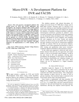
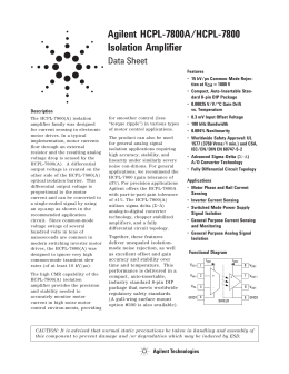
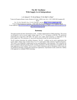
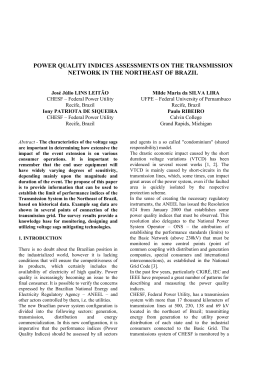
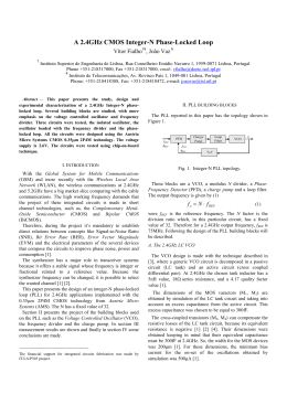
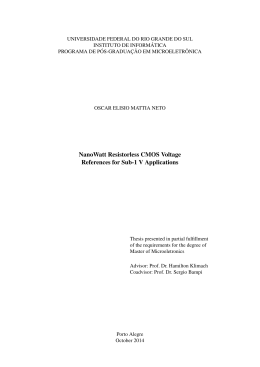
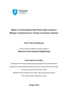
TDA4601 SWITCH-MODE POWER SUPPLY CONTROLLER .. . . LOW START-UP CURRENT DIRECT CONTROL OF SWITCHING TRANSISTOR COLLECTOR CURRENT PROPORTIONAL TO BASE-CURRENT INPUT REVERSE-GOING LINEAR OVERLOAD CHARACTERISTIC CURVE SIP9 (Plastic Package) ORDER CODE : TDA4601 DESCRIPTION The TDA4601 is a monolithic integrated circuit desi-gned to regulate and control the switching transistor in a switching power supply. Because of its wide operational range and high vol-tage stability even at high load changes, this IC can be used not only in TV receivers and video recorders but also in power supplies in Hi-Fi sets and active speakers. DIP 9+9 (Plastic Package) ORDER CODE : TDA4601B PIN CONNECTIONS 9 8 7 6 5 4 3 2 1 September 1993 DIP 9+9 VIN PULSE OUTPUT DC OUTPUT GROUND EXTERNAL FUNCTION IC SIMULATION INPUT CONTROL ZERO CROSSING VREF VREF 1 18 GROUND ZERO CROSSING 2 17 GROUND INPUT CONTROL 3 16 GROUND I C SIMULATION 4 15 GROUND EXTERNAL FUNCTION 5 14 GROUND GROUND 6 13 GROUND DC OUTPUT 7 12 GROUND PULSE OUTPUT 8 11 GROUND V IN 9 10 GROUND 1/8 4601-01.EPS - 4601-02.EPS SIP9 TDA4601 BLOCK DIAGRAM BASE CURRENT AMPLIFIER CONTROL AMPLIFIER STANDBY OPERATION TRIGGER START HOLD VOLTAGE CONTROL OVERLOAD IDENTIFICATION CONTROL LOGIC REFERENCE VOLTAGE ZERO PASSAGE IDENTIFICATION 1 2 COUPLING -CCHARGING CIRCUIT BASE CURRENT SWITCH-OFF COLLECTOR CURRENT SIMULATION EXTERNAL BLOCKING FUNCTION 4 5 3 6 4601-03.EPS START-UP CIRCUIT 8 7 9 10 to 18 Symbol V9 V1 V2 V3 V4, V5 V7, V8 I2, I3 I4 I5 I7 I8 Toper Tstg Tj Parameter Supply Voltage Reference Output Identification Input Controlled Amplifier Operating Ambient Temperature Storage Temperature Junction Temperature Value 20 6 – 0.6, 0.6 3 8 V9 – 3, 3 5 5 1.5 – 1.5 0, 85 – 40, 150 – 40, 125 Unit V V V V V Value 15 70 Unit °C/W °C/W mA mA mA A A °C °C °C 4601-01.TBL ABSOLUTE MAXIMUM RATINGS Symbol R th (j–c) Rth (j–a) Parameter Thermal Resistance Junction-pins Thermal Resistance Junction–ambient Max. Max. 4601-02.TBL THERMAL DATA ELECTRICAL CHARACTERISTICS (Tamb = 25oC) Symbol Parameter V9 Operating Supply Voltage Range Test Conditions Min. 7.8 Typ. Max. 18 Unit V 0.5 2.0 3.2 12.3 mA mA mA V I9 V9 2/8 Supply Current (V 1 not yet switched on) Switch Threshold (V 1) V9 = 2 V V9 = 5 V V9 = 10 V 11 1.5 2.4 11.8 4601-03.TBL START CONDITION (according to test circuit of fig. 1) TDA4601 ELECTRICAL CHARACTERISTICS (Tamb = 25oC ) (continued) Symbol Parameter Test Conditions Min. Typ. Max. Unit NORMAL OPERATION (V9 = 10V, Vcont = – 10V, Vclock = ± 0.5V, f = 20kHz, duty cycle 1:2 after switch on) Supply Current I9 Vref Voltage Reference at Pin 1 V3 V4 ∆V4 V5 V7 V8 ∆V8 V2 TK1 Control Voltage Collector Current Simulation Voltage Collector Current Simulation Voltage External Protection Threshold Pin 7 Output Voltage Pin 8 output Voltage Pin 8 Output Voltage Change Feedback Voltage Reference Voltage Temperature Coefficient Vcont = – 10V Vcont = 0V I1 < 0.1mA I1 = 5mA Vcont = 0V Vcont = 0V, see note 1 Vcont = 0V to –10V, see note 1 Vcont = 0V, see note 1 Vcont = 0V, see note 1 Vcont = 0V to –10V, see note 1 see note 1 110 50 4 4 2.3 1.8 0.3 6 2.7 2.7 1.6 135 75 4.2 4.2 2.6 2.2 0.4 7 3.3 3.4 2 0.2 10–3 160 100 4.5 4.4 2.9 2.5 0.5 8 4.0 4.0 2.4 mA mA V V V V V V V V V V 1/oK 22 1.5 2.1 V1 2 7.4 0.6 28 1.8 2.5 mA V V V 7.8 1 V V 450 0.5 1 30 ms V V V kHz VA PROTECTION OPERATION (V9 = 10V ; Vcont = – 10V ; Vclock = ± 0.5V ; f = 20kHz ; duty cycle 1 : 2) I9 V7 V4 V5 V9 ∆V9 Supply Current Switch–off Voltage Switch-off Voltage Blocking Voltage V5 ≤ 1.8 V V5 ≤ 1.8 V V5 ≤ 1.8 V Vcont = 0 V Supply Voltage for V8 Blocked Supply Voltage for V1 off While Further Decreasing V9 Vcont = 0 V 14 1.3 1.8 V1 − 0.1 2 6.7 0.3 ton ∆V2 Secondary Voltage Switching Time Voltage Variation with Load ∆V2 f PP Stand by Condition Stand by Frequency Primary Power Consumption in Stand by Condition S3 Closed, P3 = 20 W S2 Closed, P2 = 15 W S1 Open Ploa d = 3 W 70 350 0.1 0.5 20 75 10 12 4601-04.TBL ELECTRICAL CHARACTERISTICS (according to test circuit of fig. 2) Note 1 : Only DC component Figure 1 : Test Circuit Test Diagram : Overload Operation V 18 17 16 15 14 13 12 11 V 10 0.5 0 0.5 2 3 4 5 6 7 8 V4 9 Vcont V R = -10V VR = 0 1 10µF 0 V8 t 8 27Ω 10µF 6 V9 4 4601-04.EPS VREF I 1 V t 3 2 100kΩ D8 1N4003 10kΩ 1µF 100kΩ 10nF 22pF 20kΩ 1kΩ 2.2kΩ 0.68Ω 60 70 80 2 0 4601-05.EPS 1 10 20 30 40 t 3/8 TDA4601 Figure 2 : Test and Application Circuit 220VAC 4.7nF 4.7nF B250/ C1000 18 17 16 15 14 13 12 11 10 2.7Ω TDA4601 1N4007 C2540 1 220µF (3) 2 3 4 5 6 7 8 9 0.68Ω 200Ω MAINS SEPARATION 100µF 100 kΩ 22pF 1.2kΩ 10kΩ / 3W 100µF / 25V 6V 10 kΩ 12 kΩ 10nF (1) 270kΩ 1N4007 100µF / 16V 4.7µH 10kΩ (2) 27Ω 1µF / 35V BY258-200 8.2nF BY295-450 BU508 100Ω 22nF 9 7 15 16 11 6 12 470µF 470µF BY258 270pF -600 470µF 100Ω AZV 2 61-IC BY258 -600 470µF 25V 18V 1 4 BY258 270pF -600 BY258 270pF -600 270pF 13 150V S1 56kΩ 200V S1 56kΩ S1 470 Ω 120Ω S1 33Ω S3 V4 S2 V3 (1) C limits the max. collector current of BU508 at overshooting the permissible output power. (2) Adjustement of secondary voltage. (3) Must be discharged before IC change. 4/8 V2 V1 4601-06.EPS 56kΩ 6.8k Ω 1.5kΩ TDA4601 CIRCUIT DESCRIPTION The TDA 4601 regulates, controls, and protects the switching transistor in reverse converter power supplies at starting, normal, and overload operation. Starting Behaviour During the start-up, three consecutive operation states are passed. 1. An internal reference voltage is built up which supplies the voltage regulator and enables the supply to the coupling electrolytic capacitor and the switching transistor. Up to a supply voltage of V9 ≈ 12V, the current I9 is less than 3.2mA. 2. Release of the internal reference voltage V1 = 4V. This voltage is abruptly available when V9 ≈ 12V and enables all parts of the IC to be supplied from the control logic with a thermally stable and overload protected current supply. 3. Release of control logic. As soon as the reference voltage is available, the control logic is switched on through an additional stabilization circuit. Thus, the IC is ready for operation. This start-up sequence is necessary to guarantee the supply through the coupling electrolytic capacitor to the switching transistor. Correct switching of the transistor is only guaranteed in this way. Normal Operation Zero crossing of the feedback coil is registered at pin 2 and passed to the control logic. At pin 3 (regulation of input, overload, and standby recognition)the rectified amplitude variations of the feedback coil are applied. The regulating amplifier works with an input voltage of about 2V and a current of about 1.4 mA. Together with the collector current simulation pin 4, the overload recognition defines the operating region of the regulating amplifier depending on the internal reference voltage. The simulation of the collector current is generated by an external RC network at pin 4 and internally set threshold voltages. By increasing the capacitance (10nF) the max. collector current of the switching transistor rises, thus setting the required operating range. The extent of the regulation lies between a 2V clamped DC voltage and an AC voltage rising in a sawtooth waveform, which may vary up to a maximum amplitude of 4V (ref. voltage). A reduction of the secondary load down to 20 watts causes the switching frequency to rise to about 50kHz at an almost constant pulse duty factor (period to on-time approx. 3). A further reduction of the secondary load down to about 1 watt results in changing the switching frequency to approx. 70kHz, and additionally the pulse duty factor rises to approx. 11. At the same time the collector peak current falls below 1A. In the trigger the output level of the regulating amplifier, the overload recognition, and the collector current simulation are compared and instructions are given to the control logic. There is an additional triggering and blocking possibility by means of pin 5. The output at pin 8 is blocked at a voltage of less than 2.2V at pin 5. Depending on the start-up circuit, the zero crossing identification, and the release with the aid of the trigger, the control logic flip flops are set which control the base current amplifier and the base current shut-down. The base current amplifier moves the sawtooth voltage V4 to pin 8. A current feed-back having an external resistance of R = 0.68Ω is inserted between pin 8 and pin 7. The resistance value determines the maximum amplitude of the base driving current for the switching transistor. Protective Measures The base current shut-down, released by the control logic, clamps the output of pin 7 at 1.6V and thus blocks driving of the switching transistor. This protective measure will be released if the voltage at pin 9 reaches a value ≤ typ. 7.4V or if voltages of ≤ typ. 2.2V occur at pin 5. In the case of a short circuit of the secondary windings of the P.S.U., the IC continuouslymonitors the fault condition. With the load completely removed from the secondary winding of the P.S.U., the IC is set to a low pulse duty factor. The total power consumption of the P.S.U. is held below 6 to 10 watts in both operating conditions. After having blocked the output, causedat a supply voltage ≤ typ. 7.4V, a further voltage reduction with ∆V9 = 0.6V results in switching off the reference voltage (4V). 5/8 TDA4601 Figure 3 : Frequency versus Output Power (Test Circuit of Figure 2) Figure 4 : f (kHz) 80 100 Efficiency versus Output Power (Test Circuit of Figure 2) η (%) 80 60 60 40 40 20 20 Figure 5 : 160 120 40 60 80 100 120 Load Characteristics V2-f (Iq2) (Test Circuit of Figure 2) PO (W) 0 20 Figure 6 : 40 60 80 100 120 4601-08.EPS 0 4601-07.EPS 20 P O (W) Output Voltage V2 (mains change) (Test Circuit of Figure 2) VO2 (V) VO2 (V) 151 150 V mains = 180V V mains = 220V 149 V mains = 250V 40 I O2 (mA) 0 200 400 600 800 1000 1200 4601-09.EPS 148 Figure 7 : Example of a PC Heatsink (35°C/W) l 6/8 4601-11.EPS COPPER AREA 35µ THICKNESS Vmains (V) 147 150 170 190 210 230 250 270 4601-10.EPS 80 TDA4601 PACKAGE MECHANICAL DATA 9 PINS - PLASTIC SIP C L3 D L1 c2 d1 N 1 9 L a1 L2 A M b1 e c1 e3 PM-SIP9.EPS b3 B A a1 B b1 b3 C c1 c2 D d1 e e3 L L1 L2 L3 M N Min. Millimeters Typ. 2.7 Max. 7.1 3 24.8 Min. 0.106 0.5 0.85 Inches Typ. Max. 0.280 0.118 0.976 0.020 1.6 0.033 3.3 0.43 1.32 0.063 0.130 0.017 0.052 21.2 0.835 14.5 2.54 20.32 0.571 0.100 0.800 3.1 0.122 3 17.6 0.118 0.693 0.25 3.2 1 0.010 0.126 0.039 SIP9.TBL Dimensions 7/8 TDA4601 I b1 L a1 PACKAGE MECHANICAL DATA 18 PINS - PLASTIC POWERDIP b B e E Z Z e3 D 10 1 9 a1 B b b1 D E e e3 F i L Z Min. 0.51 0.85 Millimeters Typ. Max. 1.4 Min. 0.020 0.033 0.5 0.38 Inches Typ. Max. 0.055 0.020 0.5 24.8 0.015 8.8 2.54 20.32 0.020 0.976 0.346 0.100 0.800 7.1 5.1 3.3 0.280 0.201 0.130 2.54 0.100 Information furnished is believed to be accurate and reliable. However, SGS-THOMSON Microelectronics assumes no responsibility for the consequences of use of such information nor for any infringement of patents or other rights of third parties which may result from its use. No licence is granted by implication or otherwise under any patent or patent rights of SGS-THOMSON Microelectronics. Specifications mentioned in this publication are subject to change without notice. This publication supersedes and replaces all information previously supplied. SGS-THOMSON Microelectronics products are not authorized for use as critical components in life support devices or systems without express written approval of SGS-THOMSON Microelectronics. 1994 SGS-THOMSON Microelectronics - All Rights Reserved Purchase of I2C Components of SGS-THOMSON Microelectronics, conveys a license under the Philips I2C Patent. Rights to use these components in a I2C system, is granted provided that the system conforms to the I2C Standard Specifications as defined by Philips. SGS-THOMSON Microelectronics GROUP OF COMPANIES Australia - Brazil - China - France - Germany - Hong Kong - Italy - Japan - Korea - Malaysia - Malta - Morocco The Netherlands - Singapore - Spain - Sweden - Switzerland - Taiwan - Thailand - United Kingdom - U.S.A. 8/8 DIP18PW.TBL Dimensions PMDIP18W.EPS F 18
Download