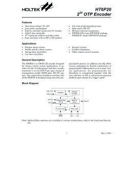
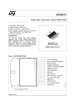
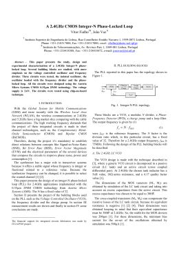
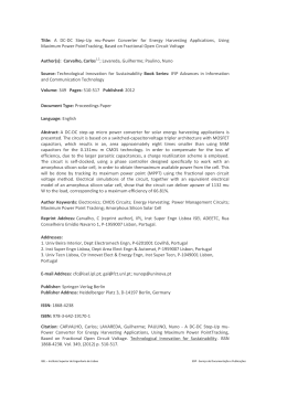
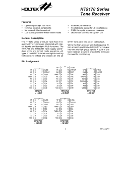
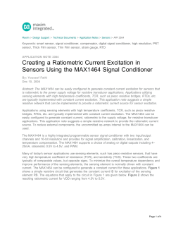
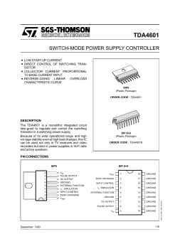
The RC Oscillator
With Supply-Level Independence
L. E. Seixas Jr.# ; W. B. de Moraes*; W. R. Melo#; S. Finco#
#
Centro de Pesquisas Renato Archer, Rodovia D. Pedro I (SP65), km 143,6 - CEP 13089-500 Campinas-SP,
Brazil
Tel.: 55 (19) 3746 6055, Fax: 55 (19) 3746 6051, web site: http://www.cenpra.gov.br
*Universidade Estadual de Campinas – UNICAMP, Rua Pandiá Calógeras nº 110, Campinas, Brasil
E-mail addresses: [email protected], [email protected], [email protected],
[email protected]
Summary
This paper presents the basic functionality of a RC - oscillator implemented in CMOS technology. This circuit
was designed to work in a power supply voltage range of 2 to 5.5 V and operate at 800 kHz. The operational
temperature has a range from -10°C 80°C. The square wave output signal frequency is independent of the
power supply level. The simulation, IC layout and experimental results are shown and discussed.
The RC products determine the oscillator frequency. This RC - oscillator can be used in applications that
require supply voltages range variation from 2 V to 5.5 V and requires stable variation of operation frequency.
This circuit is not temperature compensated, but has small dependency with temperature. This evaluation was
done by simulation during the design and the variation of frequency with the temperature is acceptable for the
target application of this oscillator. The low power CMOS construction and low dissipation of this circuit are
an operational advantage in digital data transmission applications. Experimental results confirm the viability
of the approach in a standard CMOS technology.
The RC Oscillator
With Supply-Level Independence
L. E. Seixas Jr.# ; W. B. de Moraes*; W. R. Melo#; S. Finco#
#
Centro de Pesquisas Renato Archer, Rodovia D. Pedro I (SP65), km 143,6 - CEP 13089-500 Campinas-SP, Brazil
Tel.: 55 (19) 3746 6055, Fax: 55 (19) 3746 6051, site:<http://www.cenpra.gov.br>
*Universidade Estadual de Campinas – UNICAMP, Rua Pandiá Calógeras nº 110, Campinas, Brasil
Abstract - This paper presents the basic functionality of a
RC - oscillator implemented in CMOS technology. This
circuit was designed to work in a power supply voltage range
of 2 V to 5.5 V and to operate at 800 kHz, but it is possible to
adjust at 1,2 MHz. The square wave output signal frequency
is independent of the power supply level. The simulation, IC
layout and experimental results are shown and discussed.
I. INTRODUCTION
The oscillator presented in this paper is a fully integrated
oscillator based on an RC relaxation circuit. The circuit was
designed to work with a power supply range of 2 V to 5.5 V
and the output signal is a square wave with 800 kHz. The
oscillator turn-on, turn-off, and frequency can be externally
controlled by a digital and a analog voltage level,
respectively, applied at two dedicated control pads. Special
attention was given to minimizing the current noise generated
during the switching of control transistors. The presented
oscillator circuit is currently in use in some commercially
available ASICs. This oscillator circuit was developed to
utilization in the integrated circuits with specific application
to decoding of an F-2F protocol. The designed analogue is an
association of operational amplifiers and comparators, and is
polarized by integrated monolithic resistors and capacitors,
typically configured to comply with commercial F-2F
Decoders IC. Controlled by a digital input signal ( ENA ), the
oscillator circuit generating a clock signal for the digital
circuit in the F-2F Decoder - IC. The prototype circuits, in
this work, were built in CMOS 0.6µm Technology. This
circuit are an operational advantage in various digital data
transmission applications.
II. STRUCTURAL AND FUNCTIONAL DESCRIPTION
The figure 1 show the schematic block, it is exemplify the
structural and functional description. The VDD and VSS
pads are the power supply. The ENA pad enables oscillations
and must be biased. The oscillator stays in sleep mode while
the pad control ENA is at digital low level, and oscillates
when it is at digital high level. The OUT pad is the digital
output of the oscillator.
The biasing Vb pad connects to an internal current biasing
circuit built with four resistors in series with an nmos
transistor, as shown on the left side of the schematic in Fig. 1.
If no external stimulus is applied, a voltage of approximately
1V will be present at Vb pad and the oscillator will operate at
the preset frequency of 800 kHz. The oscillator frequency can
be controlled by applying an analog voltage at Vb pad, or
through an external resistor connected to VSS or VDD. The
necessary adjustment can be predetermined more accurately
by electrical simulation.
Reference voltage levels are obtained by the current flow
through the four resistors R used in the current biasing
circuit. These resistors were built with a high resistivity
polysilicon layer. The current sources Is1, Is3 and Is4 are
pmos transistors used as polarization circuit and Is2, an nmos
transistor, completes this polarization.
Current reference level (Iref) and voltage reference levels
— an upper (Href), lower (Lref) and medium (Mref) — as
indicated in Fig. 1, depend an the VDD voltage, poly resistor
value, and nmos process parameters.
The oscillation cycle consists of charging the built-in
capacitor C up to voltage Href and discharging down to
voltage Lref.
The control of the capacitor charge and discharge is made
through the control of two current sources, Is5 and Is6, pmos
and nmos transistors
respectively and
working
complementary, as shown in Fig. 1. Both are controlled by
the output of comparator COMP1. The multiplexers MUX1
and MUX2 are CMOS switches with control circuitry.
The comparator architecture is based on a classical
topology. COMP1 associated with analog multiplexer MUX1
configures a Schmidt trigger comparator and its hysteresis is
determined by the two voltage reference levels Href and
Lref. The ENA pad acts on the control of the 2:1 analog
multiplexer MUX2 and on M5. During oscillations, channel
I1 of MUX2 connects Is5 and Is6 to the positive terminal of
capacitor C. When the output voltage of COMP1 ( Vctr ) is
at the low level, transistor M8 is open and M3 is closed,
MUX1 selects channel I0, in this circumstance the current in
Is5 is almost zero and Is6 is discharging C until Vc reaches
the low level value Lref. When Vc reaches Lref, COMP1
switches the output Vctr to high level. Thus M8 is closed, M3
is open, the current of Is6 is almost zero and the capacitor
charges due to Is5 until Vc reaches the upper level Href, and
starts a new cycle of charging and discharging the capacitor.
In sleeping mode, capacitor C is disconnected from
current sources Is5 and Is6 and is connected to Mref
reference voltage. Therefore the comparator does not switch
in this condition, and the output of the oscillator remains in a
stable condition. The comparator and the multiplexers are
current biased, so that during the switching of these cells the
maximum current noise is limited. The target application
requires this behavior as a part of electrical specification.
VDD
M1
Is1
Is3
M3
M5
curve 1
M7
Simulation (a)
Iref
Is5
Is4
curve 2
ENA
M6
R
Href
curve 3
OUT
R
Mref
R
Lref
R
curve 4
I1 MUX
1
I0
Is2
I1 MUX
COMP
Vc
2
I0
Vctr
curve 5
C
Is6
Vb
M2
M4
M8
Simulation (b)
VSS
curve 1
Fig. 1- The RC Oscillator schematic.
curve 2
III. PERFORMANCE ANALYSIS AND DISCUSSION
The reference current Iref is reflected in the ratio of 2:1 to
the Is5 and Is6 by current mirror circuitry, charging and
discharging the capacitor C by current I. The currents in Is5
and Is6 are symmetrical, so:
curve 3
curve 4
curve 5
I = Iref/2 = ((VDD -Vb) / 4R) / 2 (3.1)
I = (VDD – Vb) / 8R
(3.2)
Fig. 2 – Simulation a) at VDD=2V; b) at VDD=5V
The voltage variation on the capacitor C is:
∆Vc = Href – Lref
Href = ¾.(VDD – Vb) + Vb
Lref = ½.(VDD – Vb) + Vb
∆Vc = ½.(VDD – Vb)
Furthermore:
∆Q = C. ∆Vc
I. ∆T = C.∆Vc
(3.3)
(3.4)
(3.5)
curve 1 - shows the voltage Vc on the capacitor with the
work reference levels: Lref, Mref and Href. curve 2 - shows
the current (charge/discharge) on the capacitor. curve 3 shows the output OUT signal of the oscillator. curve 4 shows the turnoff control ENA to oscillator. curve 5 - shows
the supply current ( 140 – 340 µA )of the oscillator circuitry.
(3.6)
(3.7)
(3.8)
Then considering:
∆T = C.( ∆Vc / I )
(3.8)
∆T = C.(½.(VDD – Vb) ) / (VDD – Vb) / 8R
∆T = 4RC
(3.10)
IV. EXPERIMENTAL RESULTS
(3.9)
The figures 3 and 4 shows the experimental measurement
results obtained for VDD at 2 and 5 V for the oscillator
output signal. The measurements in both power supply
conditions agree with the expected theoretical and simulated
results. The measured value was 776.4 kHz.
and calculating the operation frequency: ∆T_charge = T/2,
where T is a period of output oscillator signal to a duty cycle
fixed to 50%.
T = 8.R.C
(3.11)
the frequency expression is:
F = 1 / 8.R..C
(3.12)
The expression (3.12) show that ideally there is no
dependence between the frequency and the supply voltage
VDD. Figure 2, a) and b) items shows some simulations
results for VDD at 2 and 5 V.
Fig. 3– The output Measure at VDD = 2V
REFERENCES
[1] Randall L. Geiger, Phillip E. Allen, Noel R. Strader:
“VLSI Design Techniques for Analog and Digital Circuits”
Published 1987.
[2] Phillip E. Allen, Douglas R. Holberg, "CMOS Analog
Circuit Design” Published, 1990.
Fig. 4 – The output Measure at VDD = 5V
V. TECHNOLOGY
The IC was build in CMOS 0.6 µm Technology, the figure 4
show the structure size: X= 243,5 µm, Y = 156,5 µm, then
0,04 mm² area.
Figure 4 - IC Layout
The process used has 13 layers, among which: 5V p-sub, 1poly, subtract “p” and double materialization. The transistors
type “p” and type “n” have: minimum width gate 0.8 µm,
minimum length gate 0.6 µm. This IC used 21 nmos and 17
pmos. The resistors types used are rpolyh - “high resistive
poly1 resistor”. The latter has a typical sheet resistance of 1.2
kΩ/sq. The “RC” circuit sets the time constant of the
oscillator, where the “R” value is 12 kΩ and “C” value is
13,5 pF. Note that the capacitance area is 50 % of the total.
VI. CONCLUSIONS
The RC products determine the oscillator frequency. This
RC-oscillator can be used in applications that require supply
voltages range variation from 2V to 5.5V and requires stable
variation of operation frequency.
This circuit is not temperature compensated, but has small
dependency with temperature. This evaluation was done by
simulation during the design and the variation of frequency
with the temperature is acceptable for the target application
of this oscillator. This circuit was designed to operate in the
range from –10 °C to 80 °C. The low power CMOS
construction and low dissipation of this circuit are an
operational advantage in digital data transmission
applications. Experimental results confirm the viability of the
approach in a standard CMOS technology.
[3] L. E. Seixas Jr., S. Finco, W. B. de Moraes, W. R. Melo,
“F-2F Decoder IC”, Proceedings The International Technical
Symposium on Packaging, Assembling and Testing 2003
IMAPS Brazil, August 6-8,2003, Campinas, São Paulo,
Brazil, pages129-131.
Download