3D Tracking in Industrial Scenarios: a Case Study at the ISMAR Tracking
Competition
Francisco Paulo Simões, Rafael Roberto, Lucas Figueiredo, João Paulo Lima, Mozart Almeida, Veronica Teichrieb
Voxar Labs
Informatics Center - UFPE
Recife, Brazil
{fpms, rar3, lsf, jpsml, mwsa, vt}@cin.ufpe.br
Abstract—One of the most challenging tasks in augmented
reality is to develop a tracking system for industrial scenarios.
This is due to the fact that this environment has characteristics
that defy most of the techniques available, such as textureless
objects that in some cases are too large and in others are
very small, as well as may be very close to each other or
occluding themselves. This work proposes the combination of
established techniques for 3D reconstruction and tracking, as
well as a calibration routine, that is suitable for this type
of scenario. This complete tracking system was validated at
the ISMAR Tracking Competition, a contest that simulates
industrial scenarios and is promoted to challenge state of the
art trackers. The case study simulated a manufacturing task in
which the environment was divided into five areas, and the user
had to be guided by the tracking system through these areas
collecting specific objects from an area to put them at a specific
location in another one. A discussion regarding the tracking
system results is lodged , aiming to introduce an analysis that
could help others during the development of their own tracking
systems for industrial scenarios.
Keywords-augmented reality; industry applications; 3D
tracking;
I. I NTRODUCTION
In recent years, Augmented Reality, or simply AR, has
received attention as a field that is changing the way people
interact with the world. In order to relate virtual content
with the real environment, AR systems are built based on
tracking techniques that can discover in real-time where the
virtual information should be added [1].
In industrial scenarios, tracking techniques can have
several applications. They can be used to help an operator
to execute a maintenance task [2] or to allow a machine to
analyze a product [3]. Unfortunately, industrial scenarios are
often difficult to track since they may have poorly textured
objects with lots of smooth surfaces. Strong light variation
is also a difficulty, as well as the size of equipment that may
be very small, among others.
When developing a tracking system for industrial
scenarios, a model-based approach is usually chosen because
of its precision [4]. However, if a model-based tracker is
employed, it is essential to associate it to an automatic
reconstruction process that will generate the 3D information
to be tracked. Besides that, a correct calibration between
the generated model and the real world may be necessary
to relate the world coordinate system with the reconstructed
and tracked coordinate system.
In order to achieve a solution capable of dealing with
some major difficulties in the industrial scenario, this work
explains the integration of a 3D model-based tracker with
a reconstruction from images technique and a calibration
routine. This tracking system was validated at the ISMAR
Tracking Competition, which aims to challenge state of
the art trackers through a simulation close to a real
world scenario. In the particular edition where our tracking
system was used, the contest simulated a manufacturing
situation, which is part of many industrial environments.
From the analysis of the contest it was possible to discuss
many problems encountered in the industrial scenario. As
far as the authors know, there is no work discussing
the use in industrial scenarios of an integrated tracking
solution using well known techniques for reconstruction,
calibration and 3D tracking. There is also no work discussing
the ISMAR contest and relating it to the industry field.
Another important contribution of this paper is to share
and discuss the experiences and challenges found during
the development of a tracker for an industrial scenario.
Therefore, this paper provides a starting point for anyone
interested in engaging into these problems from a practical
point of view.
This paper is organized as follows. In Section II recent
advances in 3D tracking, reconstruction and calibration
techniques are discussed; the development of an integrated
solution for generating 3D models, calibrating coordinate
systems and tracking is explained in Section III; Section IV
details the case study performed at the ISMAR Tracking
Competition; the result of the integrated solution at the
competition is analyzed in Section V; the lessons learned
about how to build a tracking system for an industrial
scenario are discussed in Section VI; finally, in Section VII,
major conclusions are drawn and potential future work for
tracking in industrial scenarios arises.
II. R ELATED W ORK
There are several ways to track objects. It can be
accomplished using only RGB cameras or adding other
equipment such as depth sensors [5], magnetometers [6] and
inertial sensors [7], to name only a few. The 3D tracking
system presented in this paper is a monocular one, and
therefore major state of the art techniques are discussed in
sequence for tracking, reconstruction and calibration based
on video, focusing their application to industrial scenarios.
A. Tracking
Video based tracking can be classified in two categories:
recursive tracking, where a previous pose estimate is
required for computing the current pose of the object; and
tracking by detection, where the object pose is calculated
without any previous estimate. While recursive tracking
is often faster and/or more accurate/robust, tracking by
detection allows automatic initialization and easy recovery
from failures. Existing techniques for natural feature
tracking and detection can also be classified as modelbased or model-less. Model-based methods make use of a
previously obtained model of the target object [4]. Modelless techniques are also known as Simultaneous Localization
and Mapping (SLAM) methods [8], since they estimate both
the camera pose and the 3D geometry of the scene in real
time.
Model-based techniques can be classified regarding the
type of natural feature used [9]. The recursive tracking
methods can be divided in the following categories: edge
based, where control points sampled along a 3D edge model
of the object are matched with strong gradients in the
query image [10]; template based, which aim to estimate
the parameters of a function that warps a template in a
way that it is correctly aligned to the query image [11];
and local invariant feature based, where local features that
are invariant to distortions such as rotation and illumination
changes (e.g. Harris corners [12], Good Features to Track
[13]) extracted from both model and query images are
matched [14] [15]. Model-based tracking by detection
methods can be classified in the following categories: edge
based, which make use of specific edge representations for
detecting and estimating the pose of target textureless objects
[16] [2]; and local invariant feature based, which rely on
matching local invariant features extracted from model and
query images, even if they were obtained from significantly
different viewpoints [17] [18].
modeling these complex cases is a difficult task and could
take too much time, so it may be necessary to have an
automatic 3D reconstruction of the target object.
There are several ways of making an automatic 3D
reconstruction. One of the most efficient and precise
approaches is using laser scanners [19]. With this equipment
it is possible to generate a dense 3D model of an object with
millimetric precision. The downside is that these lasers are
expensive and sometimes it is hard to use them to reconstruct
places difficult to access because of their size and weight.
Another automatic 3D reconstruction method is based on
structured lights [20]. This technique consists in projecting
on the scene light patterns that are previously known. Then,
a camera captures the projection of these light patterns.
The 3D model is calculated based on the distortion of
this projection. Since this technique requires only a simple
camera and a common projector, it is quite inexpensive,
especially when compared with the laser approach. However,
structured lights reconstructions are much more imprecise
and impossible to be used in a bright environment, such
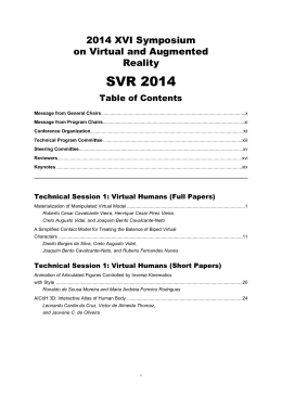
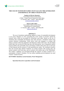
as an outdoor area during day. Figure 1 shows the result
obtained by this type of reconstruction.
The image based 3D reconstruction method is one of
the most common approaches to generate 3D models
automatically. There are also different techniques to make
this kind of 3D reconstruction work, such as SfM (Structure
from Motion) [21] and SLAM [8]. What these techniques
have in common is that they take 2D images of the scene
and use them to generate the 3D model as shown in
Figure 1. Usually that process can be done by employing
a feature detector that could be the same as the one used
during the tracking. Nowadays there are several image based
reconstruction techniques that achieve good precision [22].
Even though it is also a cheap approach since it only needs
a simple camera to take pictures or make a video of the
scene, this method is often very hard to reproduce.
B. Reconstruction
Since the model-based methods are a common approach
for markerless tracking, the acquisition of the 3D model of
the target object is an important step. Sometimes the target
object is very simple to be modeled manually, such as a
plane or a box. However, it is unlikely that in the industrial
scenario the target objects will be that simple. Manually
Figure 1. On the top row there are different views from a 3D model
generated using a structured light approach; on the bottom row, a building
reconstructed using the SfM technique.
C. Calibration
In AR applications, it is sometimes mandatory to have a
coherent scale between the 3D reconstructed model and the
real world coordinate system. For example, in an industrial
scenario the equipment are modeled based on their real
scale and could be used to augment the scene [2]. Based on
projective geometry properties, even with calibrated cameras
in which the intrinsic parameters are known, it is not possible
for a technique based only on images to directly achieve
a metric reconstruction without some input from the user.
The automatic 3D reconstruction from images is an up-toscale process and just returns a similarity reconstruction of
the object [23]. Only techniques based on depth sensors are
able to achieve a metric reconstruction directly since they
acquire from the depth sensor a real depth during the capture
process [24].
For a 3D reconstruction based on images there are several
ways to achieve a metric reconstruction. If the user knows
some 3D points from the scene and is able to correctly relate
them to the similarity reconstructed points, it is possible to
find a calibration matrix that can take all the up-to-scale
points to the metric reconstruction system [23]. When the
user has a previous 3D reconstruction of some object or part
of the scene it is possible to match these 3D models and
use an absolute orientation process to estimate the correct
alignment between them and use these information to get a
metric reconstruction [25].
III. I NDUSTRIAL S CENARIO T RACKER
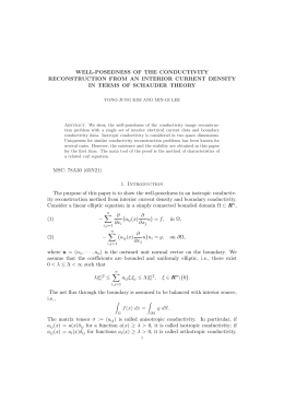
In general, the nature of objects appearance in industrial
scenarios favors the use of edge based trackers since the edge
information in these objects is more evident, and usually
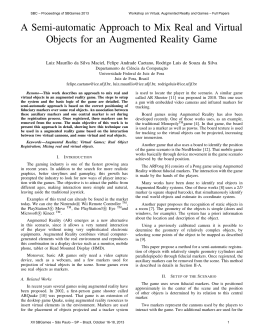
they have low texture information, as seen in Figure 4. On
the other hand, it is hard to perform real-time detection of
objects based only on their edge information. In addition,
for an edge-based tracker, when there is a crowded group
of objects, it is harder to identify each object separately.
The occlusions and the high number of nearby edges makes
difficult the task of correlating the searched edges with the
ones present in the scene. At last, in order to track each
object edges, it is needed to acquire in advance its 3D
model definitions, which is not always possible, and so an
automatic reconstruction phase is preferred.
Figure 2. Typical industrial scenario in which most of the equipment are
textureless and with edges well defined.
Taking into account all these issues, the presented
tracking system is based on invariant keypoints extraction
and matching. Even though the use of this approach is
recommended for high texturized scenarios, these keypoints
are also able to describe low texture objects as long as
there is enough color information in the whole scene. It
aims to perform real-time detection and tracking of complete
complex scenes by using an automatic 3D reconstruction
based only on images. Beyond, the system is able to
automatically initialize and recover from failures. This
feature is highly recommended for industrial scenarios since
the user of the tracking system, being a human or robot,
may navigate and focus on not traceable scene regions.
In addition, the use of invariant keypoints enables the
tracking of the scene as a whole, being not restricted to
planar scenarios or single objects tracking. Furthermore, a
metric calibration is also necessary to applications that need
to relate real coordinates from the scene and the tracked
models.
A. Tracking
The implemented tracker presented here is mainly based
on the work of Gordon and Lowe [26] and can be divided
in two phases: an off-line step in which the 3D model to
be tracked is generated and an on-line stage that consists
in keypoint extraction, description, matching and pose
calculation steps. The off-line phase will be discussed in
the next subsection.
The first step of the on-line phase consists in extracting
and describing 2D keypoints from the current image using
the Scale-Invariant Feature Transform, better known as
SIFT algorithm [17]. SIFT keypoints are invariant to scale,
illumination and viewpoint changes, being more suitable to
track objects with high color texture variation on its faces.
However, as it will be discussed in the results section, these
keypoints are also able to describe low texture objects as
long as there is enough color information in the whole scene.
After extracting and describing the SIFT keypoints, the
system matches the current image keypoints with the set of
keypoints from the reconstructed model acquired in the offline phase. This matching is done by a best bin first search
algorithm with the help of a kd-tree to speed-up the process.
Even with all the robustness of the SIFT matching, some
points could be wrongly correlated, resulting in outliers. To
remove these bad matches, the tracker was improved with
a technique that is able to validate keypoints orientations,
even when out-of-plane rotations occur [27].
Given a set of matches, it is possible to assign a 3D
coordinate from the model for each matched keypoint.
Thus, the pose calculation can be performed using a set
of 2D-3D correspondences, in which the 2D points come
from the image and the 3D are from the generated model
in the off-line phase. This knowledge allows the pose
calculation in each frame, independently of the previous
results, guaranteeing a detection behavior of the tracker and
allowing it to automatically recover from tracking failures.
The pose estimation is calculated by using the RANSAC
algorithm allied to the EPNP estimator [28].
B. Reconstruction
After the analysis of some constraints from a general
industrial scenario environment, a video based approach was
chosen to generate the 3D model of the scene. For instance,
the tracking scene may be very bright, that invalidates the
use of a structured light technique. In other situations, such
as a small warehouse, it is difficult to use a laser scanner
because of its size. Besides, this type of equipment is very
expensive, as mentioned before.
There are several image based 3D reconstruction tools
available, some of them are commercial, some are
commercial with free use for academic purposes and others
are academic. Most are based on SfM technique and need
only a few images as input to generate the 3D model. Based
on a comparison of the principal tools [29], the VisualSfM
[30] was chosen as reconstruction tool.
Some reasons were determinant to select this tool. One
is that it uses SIFT features in the reconstruction process,
which is the same used by the chosen tracker, as mentioned
before. Because of that, most of the reconstructed 3D points
come from 2D points that have a high probability to be also
extracted by the tracker, which makes the matching phase
more stable. It is important to notice that the VisualSfM
is the tool that produces the point cloud with the greater
quantity of points from the ones analyzed. To maximize
even more the extraction of correspondent points, it is a
good practice to take the pictures that will be used by the
VisualSfM with the same camera that will be used in the
tracking phase.
Another advantage of the VisualSfM is that it exports the
model as an ASCII file that has the projection matrix for
every image used in the reconstruction and all the tracks
found in the process. A track is a set that contains one 3D
point and all the correspondent 2D points used to generate
it. The track also contains one image for each one of the
2D points. So, this file is loaded and this information is
converted to the data structure that will be used in the
tracking phase. It is also possible to export the model as
.ply, a common file format for 3D models.
The VisualSfM tool has a free license policy for personal,
non-profit, or academic use as long as the tool is not
modified and the VisualSfM authors are referenced, which
is the case for this work. For commercial use, the VisualSfM
authors must be contacted for an appropriate licensing.
C. Calibration
In order to achieve a metric model to be tracked,
the presented tracker system employs a calibration phase
based on the work of Hartley and Zisserman [23]. Since
the VisualSfM provides a reconstruction ASCII file with
all intrinsic K j and extrinsic parameters [R j |t j ] for each
reconstructed camera j, it is possible to combine these
information with 2D points matched in a subset of the
images set (m j=0 , m j=1 , m j=2 ) to correctly approximate its
3D coordinates M sim , a known process called triangulation
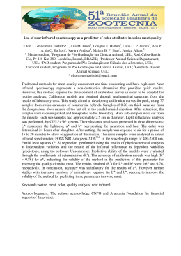
[23]. Figure 3 illustrates this procedure. In our tracker
for industrial scenarios, a subsystem based on manual
intervention was implemented to achieve this goal.
Figure 3.
Triangulation and Calibration.
After the triangulation it is possible to correlate the 3D
triangulated points (M0sim , M1sim , ..., Misim ) with known 3D
metric points (M0met , M1met , .., Mimet ) in order to estimate a
transformation matrix T[4x4] . This matrix can be applied to
all 3D points in homogeneous coordinates and take them
from the similarity model to the metric one. The metric
points Mimet are loaded from a calibration file provided by the
user with the correct measurement in real world coordinate
system. As the transformation matrix is estimated by a linear
system, there are necessary at least four correspondences
between similarity and metric points to achieve a unique
solution.
IV. C ASE S TUDY
The evaluation of a tracking system in AR applications
is not an easy issue [31]. Many efforts have been done
in the past years to provide metrics and standards to
analyze the aspects related to this problem [32] [33]
[34]. Since 2008, the International Symposium on Mixed
and Augmented Reality (ISMAR) promotes the ISMAR
Tracking Competition, a contest aiming to challenge state
of the art trackers through real world problems, therefore
stimulating breakthroughs in current solutions. All the
scenarios prepared for the competition try to replicate
real problems for tracking systems, such as lighting
conditions, task specificities, user constraints, levels of
texture information available, objects relative size, camera
resolution and others.
In 2012 the ISMAR Tracking Competition simulated a
manufacturing task in which the environment was divided
into five areas. The user, simulating a worker, had to be
guided by the tracking system through these areas collecting
specific objects from an area to put at a specific location in
another one. The only input for the tracking system was
the 3D coordinates of the objects to be picked up and
the position where they should be placed. Each area was
composed by one table with specific objects placed over it.
The level of difficulty was different for each table, depending
on the size, shape and texture of its objects. These five areas
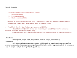
can be seen in Figure 4.
Figure 4.
ISMAR Tracking Competition manufacturing scenario: (a)
texturized planar poster with eight drinking glasses over it; (b) cardboard
box with metal pieces inside and surrounding it; (c) plastic white board
with several small pieces with different shapes, sizes and colors; (d) white
planar paper with glass goblets and plastic cups; (e) table with the position
where the picked up objects had to be dropped.
Figure 4 (a) shows that over the first table lied a texturized
poster of the ISMAR conference to simulate the simpler case
of a textured planar surface. There were also eight drinking
glasses in order to disturb the tracking by adding refraction
effects, which means that the number of outliers may be
enlarged since most of the techniques are not able to deal
with such artifact. Often industrial scenarios provoke the
presence of outliers even with robust feature detection and
matching, as discussed in the section above.
The table seen in Figure 4 (b) had several metal pieces,
some inside and others outside of a cardboard box. The goal
was to simulate areas that are difficult to access. Another
difficulty for the tracking system was the fact that they
scrambled the objects outside the box after the calibration
phase as an attempt to simulate small scenario changes
between calibration and tracking, a possible problem in
manufacturing environments.
The table in Figure 4 (c) simulated a typical
manufacturing scenario with several small pieces, some
different from each other and some with the same size and
shape. These characteristics made it more suitable for edge
based techniques and represent a common problem at many
industrial scenarios which is the absence of textures and the
similarity between objects.
In the table shown in Figure 4 (d) the organizers created
a tricky scenario with several glass goblets and plastic
cups over a textureless table. This table simulates the case
in which there are objects over a planar surface with
well-defined edges. An edge based technique would suffer
because of the glasses and a texture based is not suitable
for this textureless environment, but a simple homography
based planar tracking is capable of handling this scene.
The last area, seen in Figure 4 (e), was the target table.
It had several objects and locations for putting the objects
coming from the previous tables. Some of them were close
to each other and others were superposed. Since the objects
picked had to be dropped in one of these objects or space
locations, it analyzed the tracking precision. This table was
also composed by both textured and textureless objects.
This was the most important table since all the objects had
to be dropped there, given half of the score points in the
competition.
The contest runs during two days, being the first one
dedicated to the setup phase. Each team was allowed to
explore the room, calibrate their system, test and adjust
their tracking algorithms before the competition. In order
to calibrate the system, all teams received a file with the
metric coordinates of the 3D points corresponding to all
markers placed in room. These markers had just the function
to enable the calibration and could not be used to help the
tracking.
The actual competition happens in the second day. Every
team receives a file with the 3D points of objects that have
to be picked up from the four first tables and the position
where they must be dropped in the last one. The system has
to guide the user through this task, simulating the real world
manufacturing scenario.
V. R ESULTS
The presented tracker was developed in C++ using data
structures and basic functions from the OpenCV [35], VXL
[36], DSVideoLib [37] and OpenGL [38] libraries. The IDE
used was Microsoft Visual Studio 2010. The competition
rules state that the tracker system must run using any
device that only one person can carry and still be able to
pick up the objects. Thus, the device used was a notebook
with Intel Core i7 processor having 4 cores of 2.3 GHz
each, 8 GB of RAM memory and the NVIDIA GeForce
GTX 670M graphic card. The Microsoft LifeCam Studio
webcam provided the video and image input for tracking
and reconstruction, both with 640 x 480 pixels resolution.
Firstly, the reconstruction quality was evaluated, since it
is very important for an accurate model-based tracker. In the
setup phase several pictures of the tables were taken to be
used as input for the VisualSfM. As mentioned before, the
camera used in the reconstruction was the same as for the
tracking phase. There are not an ideal number of photos to
be used.
The first decision to make was to use a single
big reconstruction for the entire room or to use one
reconstruction for each table. If using a single reconstruction
the calibration just have to be done once and tables that
do not need to have many visible markers around each
to be calibrated. That could speed up the process and
minimize the chance of not having all tables calibrated. The
problem on this approach is to achieve a reconstruction that
contains all tables. The Visual SfM tends to maximize the
quality of the reconstruction by splitting it into a set of
reconstructions, generating one reconstruction for each set
of images that contains many textured elements in common.
That means that would be better to reconstruct each table
separately. Thus, the authors tried to use the minimum
quantity of pictures possible that could generate an adequate
reconstruction of most of the tables. This is due to the fact
that the higher the number of photos the longer the time to
perform the reconstruction [29].
In this case, there are not metrics or values defined that
can attest with certainty that the reconstruction result is
adequate, but indeed there are some indications that can
guide the evaluation process. One of them is the number
of images that the Visual SfM used for the reconstruction.
The number of 3D points composing the model tends to
increase since more pictures were used to feed it, degrading
the performance. Additionally, the reconstruction was also
visually evaluated by the percentage of the whole scene
reconstructed and the number of points that do not fit to
the real world (outliers). In some cases the result was not
good enough to enable the tracking. When that happened,
more pictures were taken and a new reconstruction was made
using the original images in addition with the new ones.
Figure 5 shows the reconstruction result for all tables. In
most of them the 3D model generated was visually coherent
with the real scene. Only the reconstruction result of table (d)
was not good, because VisualSfM uses texture information
to generate the 3D model and this table does not have this
characteristic.
The tracking system used in the competition performed
in real-time, with a FPS of 29.41 for a 320 x 240 resolution
image and 20.94 for a 640 x 480 frame. As mentioned
before, the goal was to pick up objects from four of the five
tables and drop them at a specific location in the fifth table.
The system was able to track every table individually, as can
be seen in Figure 6. However, the authors had problems to
align some of the reconstructions with the defined coordinate
system, being able to pick and release the objects from the
tables a and e that were correctly calibrated. An important
matter was that the calibration system used needs the 3D
point in metric coordinates of at least four non-coplanar
markers in each provided table. For most of the tables it
was not possible to reconstruct all of the needed markers.
In some tables there were just two or three easily visible
markers. The others were too far from the table or were in
another one.
Every table simulates a different situation in the industrial
scenario, presenting different challenges. For instance, table
(a) represents the most common case for texture based
trackers, which is a planar textured pattern. The addition
of drinking glasses represented an addition to number of
outliers in the system by the refraction. However, since
a large area of the poster remained unaffected by the
refraction, the tracker was able to keep tracking correctly
a sufficient number of features in order to calculate the
final pose. The pose also showed a good precision because
the outliers generated by the refraction related error were
discarded either in the outlier removal or in the RANSAC
processing steps.
The goal with table (b) was to collect one of the metallic
pieces in the interior of the box. Even though there were
several of these textureless objects, the SIFT algorithm
was able to extract and match the features required. This
was probably because the overall scene was treated as a
large textured pattern. Besides that, the box itself had some
texture on it, which helped the tracking technique. After the
setup phase, the competition organizer changed the metallic
objects that were outside the box. This simulates a situation
in which workers would change the environment during the
tracking. Since the box and the pieces inside it did not
change, the tracker should rely only on these parts of the
table. In Figure 6 it is possible to see that several features
were extracted from those areas.
On table (c) there was a set of organized small colored
pieces. Tracking each piece separately is a non-trivial task
for texture based trackers. However, since the pieces are
grouped in the same scene region, the overall area generates
traceable textured patterns which can be detected by the
SIFT extraction. The repetitive nature of the arrangement on
this table maybe an issue but in this case the repeatability
is not massive enough to nullify the distinctiveness property
of the extracted features.
Table (d) is specifically hard to track using keypoints
Figure 5. The reconstruction result for every table in the tracking competition. Tables (a), (b), (c) and (e) could be well reconstructed using feature
information. The exception was the table (d), that is textureless.
Figure 6. Each row shows four frames of the working tracker on a different table. The green dots are the features extracted in the frame that match with
keypoints detected in previous frames.
information. This table setup is composed mainly by a white
table cloth and a set of glass goblets and plastic cups,
containing almost no reliable color information. Figure 6
shows that only few features are tracked over the table
itself. However considering the overall scene information,
sometimes it is possible to reconstruct and track determined
scene by using not only the targeted model but also
additional parts of the environment. This way, it is possible
to perform a sort of environment tracking, in which the
tracking procedure can match keypoints with other scene
regions than the model itself. In this case, due to the presence
of the textured pattern from the floor, SIFT keypoints were
extracted and matched, making it possible to track the
camera position in the scene even without a rich textured
model as a target. This kind of tracking is not ideal since it
is needed to fit more elements in the captured frames, other
than the aimed model, however it turns to be an alternative
to guide the user in these difficult scenarios.
Finally, table (e) presented an intermediate scenario
between table (c) and table (d). It presents a few non-textured
objects over the table. These objects are generally bigger and
more complex than the ones presented in table (c), which
makes possible the identification of features even without
crowded scene parts.
The overall results of the presented tracking procedure
showed to be reliable in different scenarios regarding specific
issues like refraction, self-occlusion, non-textured targets,
planar and non-planar cases and dealing with both, crowded
scene regions and sparse objects distribution.
VI. L ESSONS L EARNED
The authors learned some important lessons from the
experience of researching, developing and validating a
tracker system for an industrial environment. By sharing
these lessons learned with the community, the authors
believe that it might help others researchers to prevent errors
or anticipate problems in the development of their own
tracking systems.
First of all, the image based reconstruction is very
important for the final result. Without a good reconstructed
model it is almost impossible to have a good tracking
based on models of the target objects. For achieving a
good reconstructed model there are often required more
matches that for the tracking itself. In order to consider a
reconstruction result a good one for tracking, there should
also be observed aspects such as percentage of the whole
scene reconstructed and types of objects reconstructed,
number of wrong reconstructed parts, number of points that
do not fit to the real world (outliers) and number of images
used in the reconstruction. For more complex scenes it could
be necessary to use more images and this could slow down
the reconstruction process. Thus, it could be interesting to
insert textured patterns on the scene for the setup phase in
order to improve scene reconstruction. There is a chance that
the tracking phase can succeed without having the textured
patterns present on the scene just because the reconstruction
is better.
The calibration is a very critical step for the tracking
to work properly, since it is necessary to have enough
reconstructed images with the calibration points visible on
them. One approach that helps to solve this problem is
to force the reconstruction algorithm to not discard some
defined images, warranting that the final reconstruction
result used them. Another possibility is to reconstruct subsets
of two or three tables together to simplify the calibration.
It must warrant that the four required calibration points
appear in it. As discussed before, a possibility is to use a
reconstruction for the entire room but to do so the system
must use a 3D reconstruction tool that does not split the
reconstruction in small sets. Sometimes it is not possible
because of the distance or obstacles between industrial areas.
Since it could degrade the reconstruction result it deserves
a deeper analysis.
Another important point is to do the calibration in a
reverse way. Instead of calibrating all the models and
then tracking the complete calibrated model, it is better to
track using the non-calibrated model and change the virtual
information to be added using the inverse calibration. This
procedure maintains the tracking more stable because the
calibration process could add error to the model.
The automatic focus and exposure control of the camera
will also add problems to the process. There are some
software as the Microsoft Lifecam that can be used to control
and fix these parameters manually. Sometimes because of the
lighting changes the algorithm gets lost and just comes back
when the focus and exposure stabilizes.
During competition it was also noted that the system
should give feedback to the user regarding tracking quality,
since industrial scenarios can have many similar objects
near each other and the user can be fooled by an incorrect
guidance caused by a tracking failure. Due to that, a message
was displayed in the title bar of the application in order to
inform the use if tracking was correct or not.
VII. C ONCLUSION
This work presented and discussed a complete system that
is able to reconstruct, calibrate and track industrial scenarios.
The main advantages and drawbacks of this procedure
were analyzed based on its results at the ISMAR Tracking
Competition that was used as a validation case study for the
system. Besides that, this paper provides a comprehensive
analysis of several aspects related to the development of a
tracker system for industrial scenarios. Thus, this article can
help other researchers and developers that are engaging in a
similar task.
As future work, it is fundamental to improve the
calibration phase of the system. Wrong calibration can lead
to tracking failures and imprecision. The use of more point
correspondences or more images in which the points are
visible may produce a better result.
In order to improve the tracking phase, the system can
employ an edge based technique that will help to achieve a
more stable multi-feature tracking (edge + texture). In case
of using a mobile device as an interface for the system, the
tracking quality can be improved by taking advantage of the
device sensors, such as the inertial, GPS or magnetometer.
VIII. ACKNOWLEDGMENTS
The authors would like to thank CNPq, FACEPE and
Reuni-UFPE 01/2012 for the scholarship of some members
of this paper (process 141853/2011-5, process 551388/20102, PBPG-0547-1.03/11 and process PBPG-0660-1.03/09), as
well as the funding of our MCT/CNPq Universal project
(process 475975/2009-0).
R EFERENCES
[1] F. Zhou, H.-L. Duh, and M. Billinghurst, “Trends in
augmented reality tracking, interaction and display: A review
of ten years of ismar,” in Mixed and Augmented Reality
(ISMAR), 2008. 7th IEEE/ACM International Symposium on.
IEEE, 2008, pp. 193–202.
[2] H. Alvarez, I. Aguinaga, and D. Borro, “Providing guidance
for maintenance operations using automatic markerless
augmented reality system,” in Mixed and Augmented
Reality (ISMAR), 2011. Proceedings. 10th IEEE International
Symposium on. IEEE, 2011, pp. 181–190.
[16] S. Hinterstoisser, V. Lepetit, S. Ilic, P. Fua, and N. Navab,
“Dominant orientation templates for real-time detection
of texture-less objects,” in Computer Vision and Pattern
Recognition (CVPR), 2010. Proceedings. IEEE Conference
on. IEEE, 2010, pp. 2257–2264.
[3] C. Wiedemann, M. Ulrich, and C. Steger, “Recognition and
tracking of 3d objects,” Pattern Recognition. Lecture Notes
in Computer Science, pp. 132–141, 2008.
[17] D. G. Lowe, “Distinctive image features from scale-invariant
keypoints,” International journal of computer vision, vol. 60,
no. 2, pp. 91–110, 2004.
[4] V. Lepetit and P. Fua, “Monocular model-based 3d tracking
of rigid objects: A survey,” in Foundations and Trends in
Computer Graphics and Vision, 2005, pp. 1–89.
[5] W. Lee, N. Park, and W. Woo, “Depth-assisted real-time 3d
object detection for augmented reality,” in Artificial Reality
and Telexistence, 2011. The 21th International Conference on,
2011.
[6] G. Reitmayr and T. W. Drummond, “Going out: robust modelbased tracking for outdoor augmented reality.”
[7] D. Kurz and S. Benhimane, “Gravity-aware handheld
augmented reality,” in Mixed and Augmented Reality
(ISMAR), 2011. Proceedings. 10th IEEE International
Symposium on. IEEE, 2011, pp. 111–120.
[8] A. Davison, “Real-time simultaneous localisation and
mapping with a single camera,” in Computer Vision, 2003.
Proceedings. Ninth IEEE International Conference on. IEEE,
2003, pp. 1403–1410.
[9] J. Lima, F. Simões, L. Figueiredo, V. Teichrieb, J. Kelner, and
I. Santos, “Model based 3d tracking techniques for markerless
augmented reality,” in Virtual and Augmented Reality (SVR),
2009. Proceedings. 11th Symposium on, 2009, pp. 37–47.
[10] H. Wuest, F. Vial, and D. Strieker, “Adaptive line tracking
with multiple hypotheses for augmented reality,” in Mixed and
Augmented Reality (ISMAR), 2005. Proceedings. 4th IEEE
and ACM International Symposium on. IEEE, 2005, pp.
62–69.
[11] A. Dame and E. Marchand, “Accurate real-time tracking
using mutual information,” in Mixed and Augmented
Reality (ISMAR), 2010.Proceedings. 9th IEEE International
Symposium on. IEEE, 2010, pp. 47–56.
[12] C. Harris and M. Stephens, “A combined corner and edge
detector,” in Alvey vision conference, vol. 15. Manchester,
UK, 1988, p. 50.
[13] J. Shi and C. Tomasi, “Good features to track,” in Computer
Vision and Pattern Recognition (CVPR), 1994. Proceedings.
IEEE Conference on. IEEE, 1994, pp. 593–600.
[14] J. Platonov, H. Heibel, P. Meier, and B. Grollmann, “A
mobile markerless ar system for maintenance and repair,” in
Mixed and Augmented Reality (ISMAR), 2006. Proceedings.
5th IEEE and ACM International Symposium on.
IEEE
Computer Society, 2006, pp. 105–108.
[15] V. Lepetit, L. Vacchetti, D. Thalmann, and P. Fua, “Fully
automated and stable registration for augmented reality
applications,” in Mixed and Augmented Reality (ISMAR),
2003. Proceedings. The Second IEEE and ACM International
Symposium on. IEEE, 2003, pp. 93–102.
[18] G. Bleser, Y. Pastarmov, and D. Stricker, “Real-time
3d camera tracking for industrial augmented reality
applications,” Journal of WSCG, pp. 47–54, 2005.
[19] G. Marshall, Handbook Of Optical And Laser Scanning,
ser. Optical Engineering. Marcel Dekker, 2004. [Online].
Available: http://bit.ly/Vsc3qG
[20] D. Lanman and G. Taubin, “Build your own 3d scanner:
3d photography for beginners,” in ACM SIGGRAPH 2009
Courses. ACM, 2009, p. 8.
[21] M. Pollefeys, “Self calibration and metric 3d reconstruction
from uncalibrated image sequences,” Ph.D. dissertation,
Leuven, 1999.
[22] S. M. Seitz, B. Curless, J. Diebel, D. Scharstein, and
R. Szeliski, “A comparison and evaluation of multi-view
stereo reconstruction algorithms,” in Computer Vision and
Pattern Recognition (CVPR), 2006. Proceedings. IEEE
Conference on, ser. CVPR ’06. Washington, DC, USA:
IEEE Computer Society, 2006, pp. 519–528. [Online].
Available: http://dx.doi.org/10.1109/CVPR.2006.19
[23] R. Hartley and A. Zisserman, Multiple View Geometry in
Computer Vision, 2nd ed. New York, NY, USA: Cambridge
University Press, 2003.
[24] R. A. Newcombe, A. J. Davison, S. Izadi, P. Kohli,
O. Hilliges, J. Shotton, D. Molyneaux, S. Hodges, D. Kim,
and A. Fitzgibbon, “Kinectfusion: Real-time dense surface
mapping and tracking,” in Mixed and Augmented Reality
(ISMAR), 2011. Proceedings. 10th IEEE International
Symposium on. IEEE, 2011, pp. 127–136.
[25] B. K. Horn, “Closed-form solution of absolute orientation
using unit quaternions,” Journal of Optical Society in
America, vol. A, no. 4, pp. 629–642, 1987.
[26] I. Gordon and D. Lowe, “What and where: 3d object
recognition with accurate pose,” Lecture Notes in Computer
Science, pp. 67–82, 2006.
[27] P. Loncomilla and J. Ruiz-del Solar, “Robust object
recognition using wide baseline matching for robocup
applications,” RoboCup 2007: Robot Soccer World Cup XI,
pp. 441–448, 2008.
[28] F. Moreno-Noguer, V. Lepetit, and P. Fua, “Accurate noniterative o (n) solution to the pnp problem,” in Computer
Vision (ICCV), 2007. IEEE 11th International Conference on.
IEEE, 2007, pp. 1–8.
[29] F. Simões, M. Almeida, M. Pinheiro, R. dos Anjos,
A. dos Santos, R. Roberto, V. Teichrieb, C. Suetsugo, and
A. Pelinson, “Challenges in 3d reconstruction from images
for difficult large-scale objects: A study on the modeling
of electrical substations,” in Virtual and Augmented Reality
(SVR), 2012 14th Symposium on, may 2012, pp. 74 –83.
[30] C. Wu, “Visualsfm: A visual structure from motion system,”
2011. [Online]. Available: http://bit.ly/rUbC5q
[31] H. Tamura and H. Kato, “Proposal of international voluntary
activities on establishing benchmark test schemes for ar/mr
geometric registration and tracking methods,” in Mixed and
Augmented Reality (ISMAR) 2009. Proceedings. 8th IEEE
International Symposium on. IEEE, 2009, pp. 233–236.
[32] D. Kurz and S. Benhimane, “Handheld augmented reality
involving gravity measurements,” Computers & Graphics,
2012.
[33] P. Moreels and P. Perona, “Evaluation of features detectors
and descriptors based on 3d objects,” International Journal
of Computer Vision, vol. 73, no. 3, pp. 263–284, 2007.
[34] T. Tuytelaars and K. Mikolajczyk, “Local invariant feature
R in Computer
detectors: a survey,” Foundations and Trends
Graphics and Vision, vol. 3, no. 3, pp. 177–280, 2008.
[35] G. Bradski, “The opencv library,” Dr. Dobb’s Journal of
Software Tools, 2000.
[36] VXL. (2012, may) Vision-something-libraries vxl. http://vxl.
sourceforge.net/.
[37] T. Pintaric. (2013, fev) Dsvideolib - free graphics software
downloads at sourceforge.net. http://sourceforge.net/projects/
dsvideolib/.
[38] Khronos. (1992, fev) Opengl - the industry standard for high
performance graphics. http://www.opengl.org/.
Download