XXX SIMPÓSIO BRASILEIRO DE TELECOMUNICAÇÕES - SBrT’12, 13-16 DE SETEMBRO DE 2012, BRASÍLIA, DF
Interference management and antenna downtilt
in multi-antenna CoMP systems
Rodrigo L. Batista, Yuri C. B. Silva, Elvis M. G. Stancanelli and Francisco R. P. Cavalcanti
Abstract— Long Term Evolution (LTE)-Advanced has
regarded both Coordinated Multi-Point (CoMP) and Multiple
Input Multiple Output (MIMO) technologies as an efficient
means of meeting the International Mobile Telecommunications
(IMT)-Advanced requirements. In this context, efficient Radio
Resource Allocation (RRA) strategies are required to exploit
the available spatial degrees of freedom, coordinate the
resources usage and manage the interference in order to obtain
performance gains. This paper provides system-level analyses in
a downlink multi-antenna CoMP system for the performance
gains achieved with the inter-cell interference management
through antenna downtilt and the use of interference estimates in
RRA strategies such as spatial precoding and power allocation.
For both spatial diversity and multiplexing schemes, the results
showed that quite high performance gains in terms of system
spectral efficiency are achieved through antenna downtilt and
that RRA strategies always benefit from estimates of the
inter-cell interference.
Keywords— Interference
management,
Multi-Point (CoMP), precoding algorithms.
Coordinated
I. I NTRODUCTION
In order to improve the performance of conventional
cellular networks, multi-cell coordinated transmission is one
of the techniques proposed in the context of Long Term
Evolution (LTE)-Advanced. By allowing coordination among
adjacent Enhanced Node Bs (eNBs), coordinated transmission
strategies can be applied at the same time that the interference
is managed [1]–[3]. Indeed, one key challenge inherent to the
Coordinated Multi-Point (CoMP) systems is to mitigate the
interference [4].
In [2], [3], Radio Resource Allocation (RRA) strategies
that exploit the cooperative transmission in CoMP systems are
investigated in order to manage the intra-cell interference. The
Channel State Information (CSI) available in CoMP systems is
used to mitigate intra-cell interference and efficiently separate
streams intended to different User Equipments (UEs) through
spatial precoding and adaptive Space Division Multiple Access
(SDMA) grouping. However, CoMP systems are also strongly
influenced by the inter-cell interference. Even though it is
unknown to RRA strategies, an estimate can be used and so
the cooperative transmission can be significantly improved.
Besides RRA strategies, downtilt antenna is also a practical
solution to reduce this inter-cell interference. Networks that
adequately adjust the antenna tilt have a much better cell
isolation against the inter-cell interference [5].
The authors are with GTEL - Wireless Telecommunications Research
Group, Federal University of Ceará, Fortaleza-CE, Brazil, E-mails:
{rodrigobatista, yuri, emiguel, rodrigo}@gtel.ufc.br. This work was supported
by the Innovation Center, Ericsson Telecomunicações S.A., Brazil, under
EDB/UFC.32 Technical Cooperation Contract.
An inter-cell interference estimate and antenna downtilt
can be used to improve RRA strategies and manage the
interference. The main contribution of this paper is to provide
system-level analyses for the performance gains achieved
with the RRA strategies for rate maximization in downlink
multi-antenna CoMP systems, as described in the following:
• Analysis of CoMP with multi-antenna nodes considering
spatial multiplexing and diversity modes;
• An inter-cell interference estimate is used on precoding
and power allocation algorithms;
• Analysis of the antenna downtilt on mitigating the
inter-cell interference.
Some notational conventions are adopted: we use italic
letters for scalars, lowercase boldface letters for vectors and
uppercase boldface letters for matrices. Calligraphic letters
are used to represent sets and | · | denotes the set cardinality.
x+ is the maximum between x and zero. pj denotes the j th
component of a vector p. diag{p} denotes a diagonal matrix,
whose elements of the main diagonal are given by the vector
p. The (i, j)th entry of a matrix is written as [·]i,j . k · k2
†
and k·kFRO denote 2- and Frobenius norms, respectively. (·)
T
H
represents the pseudo-inverse. Finally, (·) and (·) denote
transpose and conjugate transpose, respectively.
The remainder of this paper is organized as follows. In
section II, the system model is addressed. The RRA strategies
are presented in section III. Simulation results are discussed in
section IV. Finally, some conclusions are drawn in section V.
II. S YSTEM MODEL
In this section, the models adopted to evaluate the
system performance are presented. The considered scenario
corresponds to a multi-cell network with eNBs uniformly
distributed over its coverage area. It is assumed that frequency
resources can be fully reused in all cells. For downlink
CoMP, the 3rd Generation Partnership Project (3GPP) specifies
the use of Orthogonal Frequency Division Multiple Access
(OFDMA) technology. Usually, due to signaling constraints,
subcarriers are not allocated individually, but in blocks of
adjacent subcarriers, which represent the Physical Resource
Blocks (PRBs) [6]. Channel coherence bandwidth is assumed
larger than the bandwidth of a PRB, leading to flat fading over
each PRB. There exist NPRB PRBs in the system.
We consider a centralized transmission architecture for
enabling the CoMP processing, where NeNB eNBs connected
to a central controller through a backhaul network [2]
correspond to a CoMP-cell. We assume that the CoMP system
is composed of C CoMP-cells, indicated by c = 1, 2, . . . , C.
XXX SIMPÓSIO BRASILEIRO DE TELECOMUNICAÇÕES - SBrT’12, 13-16 DE SETEMBRO DE 2012, BRASÍLIA, DF
Let us assume that each eNB is placed on the corner shared
by the cells of the 3-cell site and that each cell is represented
by a regular hexagon. The number of cells per CoMP-cell
is denoted by NCELL = 3NeNB . Let us assume that each
cell is equipped with NTX directional co-located antennas
and serves a number NUE of UEs, each one equipped with
NRX co-located antennas. In general, each CoMP-cell serves a
number J = NCELL NUE of UEs uniformly distributed over its
coverage area, indicated by j = 1, 2, . . . , J. We also assume
that a CoMP-cell comprises M = NCELL NTX transmission
points, indicated by m = 1, 2, . . . , M , whose resource usage
and transmission strategies are coordinated. In this system,
each UE j can receive Lj ≤ NRX data streams and the
transmitter can send up to S ≤P
M data streams, indicated by
s = 1, 2, . . . , S, such that S =
Lj and s = (j − 1)Lj + l.
In the following, the discussion is restricted to one PRB n,
such that the index n will be omitted for simplicity of notation.
The modeling of the complex channel coefficients includes
propagation effects on the wireless channel, namely, path
loss, shadowing, short-term fading and also includes antenna
gains. For a given PRB, the complex channel coefficients
correspond to those associated with the middle subcarrier of
the considered PRB. The channel matrix Hj,c ∈ CNRX ×M that
models the link between all NRX receive antennas of the UE
j and all M transmit antennas of the CoMP-cell c is given by
T
Hj,c = hT1,j,c hT2,j,c . . . hTNRX ,j,c ,
(1)
where hr,j,c ∈ C1×M denotes the complex channel vector that
models the link between the receive antenna r of the UE j and
all M transmit antennas of CoMP-cell c, for 1 ≤ r ≤ NRX .
In the Joint Processing (JP) transmission approach, for each
PRB and CoMP-cell c, L data streams are transmitted from
M multiple transmission points to several UEs through preand post-processing at transmitter and receiver, respectively.
Each transmitted stream s, which is associated to UE j in the
CoMP-cell c, is decoded by a receive filter, which is denoted
by ds,c ∈ C1×NRX , and coded by a transmit filter ms,c , which
is given by
√
(2)
ms,c = ws,c ps,c ,
where ws,c ∈ CM ×1 is the precoding vector and ps,c ∈ R is
the transmit power allocated for the transmitted stream s.
Let us also assume that ση2 denotes the variance of Additive
White Gaussian Noise (AWGN) perceived at each UE of the
CoMP system. The downlink Signal to Interference-plus-Noise
Ratio (SINR) γs,c of the transmitted stream s associated to UE
j in the CoMP-cell c is obtained by
γs,c =
|ds,c Hj,c ms,c |2
,
inter + σ 2
intra
zs,c + zs,c
η
(3a)
S
X
(3b)
where
intra
zs,c
=
′
s 6=s
inter
zs,c
=
|ds,c Hj,c ms′ ,c |2 ,
S
C X
X
′
c 6=c s
′
|ds,c Hj,c′ ms′ ,c′ |2 .
(3c)
In the following, the discussion is restricted to one
CoMP-cell c, such that the index c will be omitted for
simplicity of notation. In the LTE downlink, the UEs measure
the perceived CSI and report it to set of transmission
points. In CoMP systems, the availability of CSI allows
the coordination by RRA strategies. The explicit feedback
mechanism in support of downlink CoMP is characterized by
having a channel part and an interference part [4]: Hj and
zsinter for all stream s in a given CoMP-cell. Even though
inter-CoMP-cell interference zsinter is unknown to the eNBs,
it can be estimated by the UE and reported to its antennas
via feedback channel. The intra-CoMP-cell interference zsintra ,
which is originated from antennas of a same CoMP-cell, can
be efficiently managed by RRA strategies, since it is assumed
perfect channel knowledge about all links within a CoMP-cell.
In this paper, RRA strategies are performed independently
for each CoMP-cell and PRB, and can be organized into:
SDMA grouping, precoding and power allocation. SDMA
grouping algorithm will select a set G ⊆ {1, 2, . . . , J} of
UEs within a CoMP-cell to receive data, where the number
of UEs it contains will be denoted by G = |G|. Then,
considering
group G, we define the channel matrix
T an SDMA
T
T
.
.
.
HTG ∈ CNRX G×M , which is used
H
H
HG =
2
1
by the precoding algorithm to mitigate the intra-CoMP-cell
interference and efficiently separate streams intended to UEs
belonging to the SDMA group
matrix
G. Herein, the precoding
for G is defined as WG = w1 w2 · · · wS ∈ CM ×S .
An equivalent channel matrix H̄G including the effect
of the receive filter can be used by any spatial precoding
algorithm instead of the channel matrix HG . This approach is
called coordinated Rx-Tx processing and is used for Multiple
Input Multiple Output (MIMO) single-cell processing in [7].
Here, it is applied for CoMP-cell processing. Let Dj =
T
T
d1,j dT2,j . . . dTLj ,j ∈ CLj ×NRX be a matrix consisting
of Lj beamformers that the UE j employs in receiving data,
the equivalent channel matrix H̄G ∈ CS×M is given as follows
H̄G = (D1 H1 )T
(D2 H2 )
T
...
(DG HG )
T T
.
(4)
Let the total transmit power PTOT available at each cell be
equally divided among the NPRB PRBs. Thus, the maximum
transmit power allocated to each PRB is given by PPRB =
PTOT /NPRB and it will draw only an upper bound on the
per-PRB transmit power of a given cell, since each cell is
shared among several UEs.
In this work, it has been assumed per-cell power constraints,
since each transmitter has a separate power amplifier with a
limited linear range per cell. However, the power allocation
problem is solved for sum-power constraint on all cells
together expressed as PSUM = NCELL PPRB . Per-cell power
constraints are respected with an additional step. Thus, RRA
strategies consider the downlink of a CoMP-cell with NCELL
cells, such that a power allocation vector for each CoMP-cell
T
is defined as pG = [p1 p2 · · · pS ] .
Considering the previous definitions, the matrix MG ∈
CM ×S comprised by the precoding matrix WG and by the
XXX SIMPÓSIO BRASILEIRO DE TELECOMUNICAÇÕES - SBrT’12, 13-16 DE SETEMBRO DE 2012, BRASÍLIA, DF
power allocation vector pG can be written as
p
T
MG = MT1 MT2 · · · MTNCELL = WG diag {pG },
(5)
where Mi ∈ CNTX ×S , ∀ 1 ≤ i ≤ NCELL , is the part of the
matrix MG relating to the cell i and all S streams.
III. RRA STRATEGIES
Initially, we focused on the RRA subproblem of determining
a suitable set of UEs to spatially reuse a given radio resource
among multiple geographically separated transmission points,
having as objective the maximization of the total system
throughput. After that, the multiple transmission points are
treated as a distributed antenna array to perform Multi-User
(MU)-MIMO and mitigate the intra-CoMP-cell interference
and/or improve the received signal quality of grouped UEs
G. The degrees of freedom available due to the multiple
antennas at both transmitter and receiver can be used for
spatial multiplexing, spatial diversity or both. Once the set
of the grouped UEs G is defined, it is necessary to perform
an adequate power allocation among data streams. In order
to achieve efficiency on the usage of considered resource, the
effect due to spatial precoding as well as the effect of the
inter-CoMP-cell interference can be considered by the power
allocation algorithm.
Another important aspect to be considered by RRA
strategies is the inter-CoMP-cell interference management.
Even though the inter-CoMP-cell interference is unknown to
CoMP-cell, it can be estimated and so the link adaptation
can be significantly improved. In addition, by downtilting the
transmit antennas, the inter-CoMP-cell interference is reduced
and the link quality at the UE is improved [5].
In the following, a simple inter-CoMP-cell interference
estimation mechanism and the transmit antenna downtilt
feature are treated in section III-A. Spatial multiplexing and
diversity schemes are introduced in section III-B, SDMA
grouping is presented in section III-C, spatial precoding
is described in section III-D, power allocation is detailed
in section III-E and power scaling is treated in section III-F.
A. Inter-CoMP-cell interference management
In an effort to reduce the inter-CoMP-cell interference,
we employed the downtilt feature. With this feature, the
antenna orientation is adjusted towards a given region within
the coverage area, thereby enhancing the desired signal and
diminishing the interference received by a UE in that region.
In other words, the downtilt feature can provide a better
cell isolation. Although the antenna tilt may be achieved
electrically and/or mechanically, herein we assumed just the
electrical downtilt approach.
The horizontal-only antenna radiation pattern adopted by
the 3GPP is given in dB as [8]:
n
o
(a)
2
Ghorizontal−only (θ) = − min 12 (θ/70) , 20 + 14, (6)
where θ is the azimuth in degrees. Note that this model does
not allow one to model tilted antennas. In fact, the downtilt
feature requires an antenna radiation pattern model defined
over both the horizontal and vertical planes, such as that one
described in [5], which is given in dB as:
(a)
2
Ghorizontal (θ) = − min 12 (θ/65) , 30 + 18,
(7)
(a)
2
Gvertical (φ) = max −12 ((φ−φtilt )/6.2) , −18 ,
where φ is the negative elevation angle and φtilt the electrical
downtilt angle, all in degrees.
Furthermore,
we
considered
an
approach
for
inter-CoMP-cell interference estimation through which
the link adaptation can be significantly improved. Taking
the inter-CoMP-cell interference measurement capability of
a given UE and PRB into account, we employed the last
measured interference value, zsinter at the last Transmission
Time Interval (TTI), as the inter-CoMP-cell interference
estimate z̃sinter of the stream s at current TTI [2], [3].
B. Spatial multiplexing and diversity schemes
In this paper, one of the following reception schemes is used
for both precoding at the transmitter and demodulation at the
UE when it is equipped with multiple antennas:
• Spatial
multiplexing scheme: All NRX available
dimensions at each UE j are used, i.e., multiple-stream
transmission per UE j is employed regarding Lj = NRX .
The receive filter Dj for each UE j is selected by
choosing I ∈ CNRX ×NRX ;
• Spatial diversity scheme: Only Lj = 1 stream is
considered for each UE j, i.e., single-stream transmission
per UE. Coordinated Rx-Tx processing is assumed, which
is stated in section II. Herein, the total number of streams
S per CoMP-cell is reduced from S = NRX G ≤ M to
S = G. Let the Singular Value Decomposition (SVD)
of Hj be represented by Hj = Uj Σj VjH , where Uj
contains the Lj dominant left singular vectors of Hj .
The receive filter Dj ∈ C1×NRX for each UE j is set to
be the first line of UH
j [7].
C. SDMA grouping
Normally, SDMA grouping algorithms are heuristics
composed by two elements: a grouping metric and a
grouping algorithm [9]. While the metric measures the spatial
compatibility among the UEs based on the CSI available at
the CoMP-cell, the grouping algorithm, based on the grouping
metric, builds and compares different SDMA groups. Here we
consider the grouping metric (sum of channel gains with null
space successive projections) and grouping algorithm (Best
Fit) described in [2].
D. Spatial precoding
Assuming a particular PRB and a CoMP-cell subject to
a sum power constraint, the spatial separation of S data
streams is accomplished by employing spatial precoding
techniques [10], which adaptively weigh the symbols
transmitted from M transmit antennas.
Minimum Mean Square Error (MMSE) precoder can trade
intra-CoMP-cell interference suppression against effective
XXX SIMPÓSIO BRASILEIRO DE TELECOMUNICAÇÕES - SBrT’12, 13-16 DE SETEMBRO DE 2012, BRASÍLIA, DF
channel gains efficiency [11]. The precoding weights improve
the ratio of the signal gain to the intra-CoMP-cell interference
plus noise. Thus, precoding reaches a balance between
achieving strong signal gain and limiting intra-CoMP-cell
interference. The optimal MMSE precoder is given by [11]
−1
,
(8)
WG = HG H HG HG H + ΨG
where ΨG ∈ CS×S is a diagonal matrix, whose sth diagonal
element is given by
2
ση ,
for SNR-based MMSE,
PPRB
(9)
[ΨG ]s,s =
2
inter
ση +z̃s
, for SINR-based MMSE.
PPRB
E. Power allocation
Assuming a sum power constraint PSUM for all cells of
a CoMP-cell, as defined in section II, we shall consider the
Water-filling (WF) power allocation scheme. WF is the optimal
power allocation scheme to maximize system throughput when
CSI is known at the transmitter when sum-power constraint is
considered.
Given a certain spatial precoding, the sum-rate can be
maximized by solving the following optimization problem [12]
max
S
X
s=1
log2 1 +
ps
z̃sinter + ση2
,
S
P λ p ≤ P
s s
SUM ,
s.t. s=1
ps ≥ 0.
The factor λs of the stream s is given by [12]
h
−1 i
λs = HG HG H + ΨG
,
s,s
(10)
where the choice of this factor λs for MMSE precoding is
only an approximation for the problem defined above, since
the intra-CoMP-cell interference is not taken into account.
The optimal user power allocation can be obtained by the
well-known WF solution [12].
h
i+
µ − ση2 ,
for SNR-based WF,
λ
h s
i+
ps =
µ − z̃ inter + σ 2
, for SINR-based WF,
s
η
λs
(11)
where the water level µ is chosen to meet the sum power
S
P
λs ps = PSUM . Note that the SINR-based
constraint,
s=1
power allocation depends on estimates of the inter-CoMP-cell
interference, which can be dynamically adjusted.
F. Power scaling
Because no cell can use more power than PPRB and
the power ratio among elements of each column of the
matrix MG cannot be changed in order to preserve the
properties of the spatial precoding, the per-cell power
constraints are respected by scaling the whole precoding
matrix MG [2], [3]. Considering the precoding matrix MG ,
the power scaling can be handled as follows. First, we
choose the cell i∗ which consumes the highest power: i∗ =
arg max1≤i≤NCELL kMi kFRO . Then, the scaling of the whole
MG matrix is performed so that the squared norm
of the
√
row Mi∗ with highest norm becomes equal to PPRB , i.e.,
MG = MG / kMi∗ kFRO .
IV. R ESULTS
Through system-level simulations, this section provides a
performance assessment of the RRA strategies introduced
in section III on a multi-antenna CoMP system. Our
simulation tool is aligned with the 3GPP LTE-Advanced
architecture (specifications [4], [6], [8], and [13]), regarding
the explicit feedback model defined in [4]. The main
parameters considered are summarized in Table I.
TABLE I
S IMULATION PARAMETERS AND SETTINGS .
Parameter
Number of CoMP-cells
Number of cells per CoMP-cell
Number of antennas per UE
Number of antennas per cell
Environment cell
Site-to-site distance
UE
Antenna height
eNB
Average UE speed
Carrier frequency
Number of PRBs
Electrical downtilt angle
Path loss model
Channel model
Shadowing standard deviation
CSI Knowledge
Required SNR at the cell-edge
Link adaptation
Transmission schemes
no downtilt
Transmit power
w/ downtilt
SDMA algorithm
Spatial precoding
Power allocation
Traffic model
Snapshot duration
Effective TTI duration
Value
7 (w/ wrap-around [1])
21
1 or 2
1 or 2
Urban-micro scenario, NLOS [8]
500 m [8]
1.5 m [8]
12.5 m [8]
3 km/h [6]
2.0 GHz [6]
6 [6]
8o [5]
35.7 + 38 log10 (distance) dB [8]
SCM [8]
8 dB
Ideal
- 6.2 dB
MCSs according to [13]
Spatial diversity and multiplexing
29.3 dBm
40.0 dBm
BF and SP [2]
ZF and MMSE [10], [11]
EPA and WF [12], [14]
Full buffer [8]
1s
1 ms
For the sake of simplicity, the configuration of co-located
antennas at the cells and UEs is represented as NTX × NRX .
It is important to highlight that the transmit power per
PRB for each cell is determined according to the scenario,
viz. transmission scheme, antenna configuration and downtilt
feature. Herein, it is determined in order to assure that any
stream of UE at the cell edge should perceive the minimal
Signal to Noise Ratio (SNR) required for achieving the
lowest Modulation and Coding Scheme (MCS) without spatial
precoding. Note that the maximum transmit power per PRB
for spatial multiplexing schemes is NTX (number of transmit
antennas per cell) times the transmit power given in Table I.
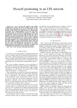
In the following, we present the system spectral efficiency
of the RRA strategy as a function of the offered load, for
two basic multi-antenna scenarios: a spatial diversity-based
scenario, in Fig. 1, and a spatial multiplexing-based scenario,
in Fig. 2. For each scenario, we evaluate the effect of the use
of the inter-CoMP-cell interference estimate as well as the
benefits of achieving the transmit antennas downtilt.
As we can note in Fig. 1 , the gain achieved with the use of
the estimate of the inter-CoMP-cell interference is practically
negligible in a scenario with antenna downtilt. In scenario 1x1
without antenna downtilt, this gain was of about 12.73% for
XXX SIMPÓSIO BRASILEIRO DE TELECOMUNICAÇÕES - SBrT’12, 13-16 DE SETEMBRO DE 2012, BRASÍLIA, DF
9
System spectral efficiency [bit/s/Hz/cell]
System spectral efficiency [bit/s/Hz/cell]
5.5
5
4.5
4
1x1 MMSE-SNR WF-SNR
1x1 MMSE-SINR WF-SINR
2x2 MMSE-SNR WF-SNR
2x2 MMSE-SINR WF-SINR
1x1 MMSE-SNR WF-SNR w/ downtilt
1x1 MMSE-SINR WF-SINR w/ downtilt
2x2 MMSE-SNR WF-SNR w/ downtilt
2x2 MMSE-SINR WF-SINR w/ downtilt
3.5
3
2.5
2
2
3
4
5
6
7
8
Load [UE/cell]
Fig. 1.
Spatial diversity analysis.
the lowest load. In fact, the antenna downtilt has better cell
isolation, reducing the inter-CoMP-cell interference and thus
enhancing the received signal power through a better antenna
orientation, such that the estimate of the inter-CoMP-cell
interference is not so necessary. Besides that, we observed that
the performance improvement due to spatial diversity gain is
also possible with the downtilt feature: regarding the lowest
load, the gain in performance achieved from the configuration
1x1 to the configuration 2x2 is of about 20% and 28.9%,
respectively, with and without antenna downtilt.
From Fig. 2, it can be seen that the use of an estimate
for the inter-CoMP-cell interference in the scenario 2x2 with
antenna downtilt also provided a significant gain as well as
it was provided in the scenario without antenna downtilt,
although now lower gains are achieved. This gain is between
5% and 10% while in the scenario without antenna downtilt the
observed gain ranges between 13% and 23% for all considered
loads. This is because the antenna downtilt feature reduces the
inter-CoMP-cell interference.
V. C ONCLUSIONS
The main objective of this work was to study RRA strategies
that aim at maximizing the throughput of a multi-antenna
CoMP system. The results showed that quite high throughput
gains are achieved through intelligent RRA strategies.
In the case with antenna downtilt, we have seen that
the spatial diversity-based transmission scheme has provided
satisfactory gains, especially for low loads in UEs per cell.
The spatial diversity-based multi-antenna CoMP system has
performance close to its maximum capacity in situations of
high diversity of UEs per cell. In fact, the antenna downtilt has
better cell isolation reducing the inter-CoMP-cell interference
and thus enhancing the received signal power through a better
antenna orientation. In general, MMSE and WF always benefit
from estimates of the inter-CoMP-cell interference, achieving
performance gains in terms of spectral efficiency. Finally, the
results indicate that the multi-antenna CoMP communication is
a very promising technology to increase the spectral efficiency
8
7
6
5
4
3
2x2 MMSE-SNR WF-SNR
2x2 MMSE-SINR WF-SINR
2x2 MMSE-SNR WF-SNR w/ downtilt
2x2 MMSE-SINR WF-SINR w/ downtilt
2
1
0
2
3
4
5
6
7
8
Load [UE/cell]
Fig. 2.
Spatial multiplexing analysis.
in the LTE-Advanced context. In further works, a dynamic
SDMA group size as well as an FTP-like traffic model could
be considered in order to analyze the impact of fluctuations
on inter-CoMP-cell interference estimates.
R EFERENCES
[1] L. H. Zheng Feng, Wu Muqing, “Coordinated Multi-Point Transmission
and Reception for LTE-Advanced,” in Proc. IEEE Wireless
Communications, Networking and Mobile Computing (WiCOM),
Sep. 2009, pp. 1–4.
[2] R. Batista, R. dos Santos, T. Maciel, W. Freitas, and F. Cavalcanti,
“Performance evaluation for resource allocation algorithms in CoMP
systems,” in Proc. IEEE Vehicular Technology Conference (VTC), Sep.
2010, pp. 1–5.
[3] R. Batista, T. Maciel, Y. Silva, and F. Cavalcanti, “SINR balancing
combined with SDMA grouping in CoMP systems,” in Proc. IEEE
Vehicular Technology Conference (VTC), Sep. 2011, pp. 1–5.
[4] 3GPP, “Further advancements for E-UTRA physical layer aspects,”
3GPP, Tech. Rep. TR 36.814 V9.0.0, Mar. 2010.
[5] F. Gunnarsson, M. Johansson, A. Furuskar, M. Lundevall, A. Simonsson,
C. Tidestav, and M. Blomgren, “Downtilted base station antennas - a
simulation model proposal and impact on HSPA and LTE performance,”
in Proc. IEEE Vehicular Technology Conference (VTC), Sep. 2008, pp.
1–5.
[6] 3GPP, “Physical layer aspects for evolved universal terrestrial radio
access (utra),” Third Generation Partnership Project, Tech. Rep. TR
25.814 V7.1.0, Sep. 2006.
[7] Q. Spencer, A. Swindlehurst, and M. Haardt, “Zero forcing methods
for downlink spatial multiplexing in multiuser MIMO channels,” IEEE
Trans. Signal Processing, vol. 52, no. 2, pp. 461–471, Feb. 2004.
[8] 3GPP, “Spatial channel model for MIMO simulations,” 3GPP, Tech.
Rep. TR 25.996 V6.1.0, Sep. 2003.
[9] T. Maciel and A. Klein, “On the performance, complexity, and fairness
of suboptimal resource allocation for multi-user MIMO-OFDMA
systems,” IEEE Transactions on Vehicular Technology, vol. 59, no. 1,
pp. 406–419, Jan. 2010.
[10] V. Stankovic, “Multi-user MIMO wireless communications,” Ph.D.
dissertation, Technische Universität Ilmenau, Germany, Nov. 2006.
[11] G. Li, X. Zhang, X. Liu, and D. Yang, “Joint combiner and precoding
in MU-MIMO downlink systems with limited feedback,” in Proc. IEEE
Vehicular Technology Conference (VTC), Sep. 2011, pp. 1–4.
[12] H. Nguyen-Le, D. H. N. Nguyen, and T. Le-Ngoc, “Game-based
zero-forcing precoding for multicell multiuser transmissions,” in Proc.
IEEE Vehicular Technology Conference (VTC), Sep. 2011, pp. 1–5.
[13] 3GPP,
“Physical
layer
procedures,”
3GPP,
Tech.
Rep.
TR 36.814 V10.0.1, Dec. 2010.
[14] J. Jang and K. B. Lee, “Transmit Power Adaptation for Multiuser OFDM
Systems,” IEEE Journal on Selected Areas in Communications, vol. 21,
no. 2, pp. 171–178, Jan. 2003.
Baixar