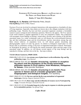
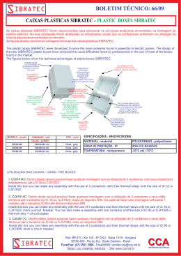
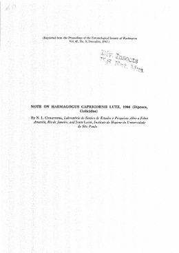
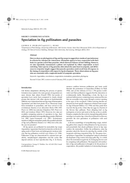
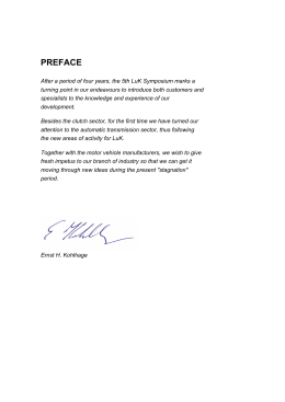
your reliable partner
ROBA®-slip hubs
Load-holding, frictionally-locking
safety clutches
K.123.V13.EN
www.
.com
your reliable partner
ROBA® – a Well-known Trade Name
ROBA®-slip hub the load-holding,
frictionally-locking safety clutch
Design
ROBA® is a trade name which has been the symbol of quality
and experience in clutch construction for decades. A
comprehensive range of torque limiters has originated from
the robust jaw clutch (ROBA®-safety slip clutch).
ROBA®-slip hub devices are simple to use. The torque table
makes it possible to set the torque according to a scale and
offers considerably simplified installation. ROBA®-slip hub
devices are reasonably-priced drive elements which protect
machinery and equipment against costly damage, and
against downtimes resulting from time-consuming repairs.
As a result of their high-strength materials and careful
manufacture with optimum utilisation of space, ROBA®-slip
hub devices are smaller than similar clutches on the market.
Twelve different designs and combinations are available. We
have a solution for all drive units. However, if any of your
wishes remain unanswered, please contact us.
Despite their simple construction, ROBA®-slip hub devices
are high-quality machine components. The ROBA®-slip hub
is fully machined and phosphated and, therefore, protected
against rust. It is a fully enclosed construction, so that dirt is
prevented from reaching internal components.
The ROBA®-slip hub, which is a rotating component, fits
very easily into all drive systems as a result of its smooth
construction. It is particularly suitable for attachment to the
outside of machines and for those systems which must be
kept clean easily, e.g. in the food industry.
ROBA®-slip hub devices are designed in such a way that
they can be adapted very easily to the most varied of working
conditions, e.g. high slipping frequency and low torque or
low friction work and extremely high torque, as well as all
intermediate stages of torque and friction work, and the
desired lifetime.
ROBA® stands for: trust in safety.
Application
ROBA®-slip hub devices are used as overload protection
for machine drives with chain sprockets, toothed wheels or
pulleys. The ROBA®- slip hub is used wherever expensive
and sensitive motors, gearboxes or machinery components
need to be protected against overloads. If overload occurs,
the drive element slips and, therefore, limits the torque.
ROBA®-slip hub devices are used in packing machines,
transport systems and equipment, construction machinery,
textile machinery, agricultural machinery, mechanical handling
equipment, feed units, loading systems, in equipment for
the chemical industry and in machinery and equipment in
general industrial engineering.
Positive-locking torque adjustment
securement via the lock washer
and the locking screw
to prevent the adjusting nut
loosening
Asbestos-free friction linings with
a large surface area and a low
wear rate ensure a long lifetime.
The bearing bushing
width can be shortened to suit
the width of the drive element.
Four wide claws
engage in the keyways
of the hub and guarantee
reliable torque transmission
even under impact loads
or reversing load conditions.
The short, robust hub
ensures compact overall dimensions
for the complete slip hub, together with
easy assembly and fitting.
The set screw
applies pressure onto the
keyway of the shaft, preventing
axial movement of the slip hub.
Adjusting nut together
with a graduation scale
for simple torque adjustment
and wear re-adjustment
A speed monitor
(available on request)
prevents excessively
long drive element slippage
or serves on the output
to monitor the chain drive
against breakage.
2
Cup springs with
low characteristic curve
keep torque reduction due
to wear low. Alternative
spring layerings ensure a
wide torque range per size.
Fig. 1 Type 100.110
your reliable partner
Contents
Functional Description
Part List Sizes 0 – 5
Page
1. Hub
12
5
6
4
2. Thrust washer
ROBA®-slip hubs
3
3. Adjusting nut 0
Torque range: 2 to 50.000 Nm
in special design up to 200.000 Nm
1
2
7
13
8
4. Locking screw
5. Cup springs
6. Friction linings
Description3
7. Bearing bushing
Summary of Constructional Designs
8. Adjusting screw
12.Chain sprocket
13.Lock washer
9
6
14
1
2
7
• ROBA®-slip hub standard
6
• ROBA®-slip hub with standard chain sprocket8
• ROBA®-Co-Pro® Part List Sizes 6 – 12
12
Data Sheets
• ROBA®-slip hub with rustproof friction lining9
Fig. 2 Type 100.110, Sizes 0 – 5
5
4
10
• ROBA®-clamp11
• ROBA®-min12
1. Hub
2. Thrust washer
5. Cup springs
6. Friction linings
• ROBA®-max13
• ROBA®-slip hub with needle bearing14
• ROBA®-lastic – torsionally flexible15
7. Bearing bushing
• ROBA®-lastic – positive-locking16
9. Cup spring
supporting bolt
• ROBA®-lastic – highly flexible17
• ROBA®-LD – torsionally rigid18
12.Chain sprocket
Technical Explanations 19
Torque Adjustment 21
Installation Examples
22
14.Adjusting nut 0
Fig. 3 Type 100.110, Sizes 6 – 12
Function
The drive element (12) (chain sprocket or V-belt disk) is
placed on the bushing (7) as shown in Figure 2 and clamped
between the friction linings (6) with the aid of the thrust
washer (2), the cup springs (5) and the adjusting nut (3) with
the lock washer (13). The more powerfully the cup springs (5)
are compressed by the adjusting nut (3), the higher the
torque at which the drive element (12) slips. The precise
torque adjustment operation is described on page 21.
It should also be noted that the difference in torque after friction
lining wear is lowest with single cup spring layering and
highest with triple cup spring layering. In addition, a torque
adjustment in the uppermost quarter of the maximum
torques gives a particularly even adjustment (the spring
characteristic curve has its smallest increase in this area).
Other friction linings are also available for special applications
(see further details on page 19).
The ROBA®-slip hub is available for three different torque
ranges.
Rule of thumb:
12
1
ROBA®-slip hub for high friction
work and low torque (single-layer
cup springs, single contact force).
6
8
ROBA®-slip hub for medium friction
work and higher torque (doublelayer cup springs, double contact
force).
5
6
7
Fig. 4 Type 100.110, Sizes 0 – 5
2
13
3
4
ROBA®-slip hub for low friction work
and very high torque (triple-layer
cup springs, triple contact force).
Please observe the
operating speed or
slipping speed (see
Explanation on page
19)!
3
your reliable partner
ROBA®-slip hubs Summary of Constructional Designs
ROBA®- slip hub
standard
Torque:
2 to 50.000 Nm
Sizes 0 to 12
Type 100._ _ _
• Safety clutch for machine drives requiring protection against
overload.
When the preset overload torque is reached, the drive
element slips, preventing damage to the drive system.
Page 6
ROBA®-slip hub
with standard
chain sprocket
Torque:
6 to 1.400 Nm
• Slip hub complete with chain sprocket as a reasonablypriced drive element with a high safety factor for all chain
drives
Sizes 01 to 5
Type 100._ _ _
Page 8
ROBA®-slip hub
with rustproof
friction linings
Torque:
6 to 2.400 Nm
• For drives in open air installations, particularly wet ambient
conditions or for long downtimes
Sizes 01 to 6
Type 100._2_
Page 9
ROBA®-Co-Pro®
Torque:
5 to 1.500 Nm
Sizes 30 to 50
Type 1000._1000
Type 1010._1000
• Compact, high performance safety clutch
Hub designs:
Design M
Design L
Type 1000._1000
Type 1010._1000
Page 10
ROBA®-clamp
Torque:
2 to 400 Nm
Sizes 0 to 2
Type 106._ _ _
• For shaft ends without a keyway. Enables easy and fast
shaft installation.
• The keyless slip hub is better suited to larger shafts than the
standard design.
Page 11
ROBA®-min
Torque:
8 to 1.100 Nm
Sizes 1 to 5
Type 121._ _ _
Type 123._ _ _
4
• For drive elements with particularly small diameters and very
large installation widths
• Larger installation width than Type 100, but only capable of
transmitting lower torques
Hub designs:
short hub
long hub
Type 121._ _ _
Type 123._ _ _
Page 12
your reliable partner
ROBA®-slip hubs Summary of Constructional Designs
ROBA®-max
Torque:
2 to 2.100 Nm
Sizes 0 to 5
Type 170._ _ _
• For drive elements (chain sprockets, toothed wheels etc.)
with particularly large installation widths (e.g. double-row
chain sprockets). Same product width as Type 123, but is
capable of transmitting higher torques.
Page 13
ROBA®-slip hub
with needle bearing
Torque:
9 to 1.260 Nm
• For drive elements with larger radial loads, a higher
slipping frequency and increased shaft run-out accuracy
(e.g. toothed wheels)
Sizes 1 to 5
Type 160._ _ _
Page 14
ROBA®-lastic torsionally
flexible
Torque:
2 to 1.400 Nm
Sizes 0 to 5
Type 135._ _ _
• Torsionally flexible safety clutch for connection of two
shafts
• The flexible coupling component is designed as a simple
plug-in coupling.
Page 15
ROBA®-lastic positive-locking
Torque:
240 to 50.000 Nm
Sizes 6 to 12
Type 132._ _0
• Positive-locking, torsionally flexible safety clutch for
connection of two shafts
• Flexible coupling component is designed as a torsionally
flexible plug-in coupling.
Page 16
ROBA®-lastic highly flexible
Torque:
2 to 2.400 Nm
• Highly flexible safety clutch for connection of two shafts
• Flexible coupling component with high damping
characteristics
Sizes 0 to 6
Type 131._ _ _
Page 17
ROBA®-LD torsionally
rigid
Torque:
14 to 6.800 Nm
Sizes 1 to 8
Type 133._ _ _
Type 134._ _ _
• Torsionally rigid safety clutch for connection of two shafts
• Flexible coupling component is designed as a torsionally
rigid flexible all-steel coupling. Type 133 is designed with a
short, torsionally rigid coupling. Type 134 is designed with a
long, torsionally rigid coupling.
Sleeve Designs:
short sleeve
long sleeve
Type 133._ _ _
Type 134._ _ _
Page 18
5
your reliable partner
ROBA®-slip hub standard
Type 100._ _ _
Sizes 0 to 12
Sizes 0 to 5
Types 100.1_ _, 100.2_ _ and 100.3_ _
bmax
k
Øh
SW
G
Øu
Ø dmax
Ø d1
Ø DN
ØD
g
ØH
v
s
B
bmin
L
Fig. 5
Type 100.110
Sizes 6 to 12
Types 100.1_ _ and 100.2_ _
bmax
s
Øh
SW
G
ØH
Ø dmax
Ø d1
Ø DN
ØD
g
B
Fig. 6
Type 100.110
6
bmin
L
your reliable partner
ROBA®-slip hub standard
Technical Data (Sizes 0 to 5)
Type 100.11_
Type 100.21_
Type 100.3_ _
Type 100.3_2
Limit torques
for overload
Operating speed 1)
Weight (pilot bored)
Technical Data (Sizes 6 to 12)
Operating speed 1)
Weight (pilot bored)
Dim.
B
[mm]
Size
0
01
1
2
3
4
5
6
7
8
9
10
11
12
8,5
16
17
19
21
23
29
31
33
35
53
60
73
79
b
bmin
bmax
2
3
3
4
5
6
8
8
8
8
12
15
20
25
6
8
10
12
15
18
20
23
25
25
28
35
45
55
0
2 – 10
10 – 20
18 – 30
8500
0,3
MG [Nm]
MG [Nm]
MG [Nm]
MG [Nm]
nmax [rpm]
[kg]
01
6 – 30
30 – 60
60 – 90
6600
0,6
6
Type 100.11_
Type 100.21_
Limit torques
for overload
We reserve the right to make dimensional and constructional alterations.
Size
1
2
3
4
5
14 – 70
26 – 130 50 – 250 110 – 550 140 – 700
70 – 130 130 – 250 250 – 550 550 – 1100 700 – 1400
130 – 200 250 – 400
550 – 800 1100 – 1600 1400 – 2100
5600
4300
3300
2700
2200
0,9
1,6
3,1
5,4
9,0
Size
9
10
11
12
MG [Nm] 240 – 1200 400 – 2000 680 – 3400 1200–6000 2000 – 10000 3400 – 17000 5000 – 25000
MG [Nm] 1200 – 2400 2000 – 4000 3400 – 6800 6000–12000 10000 – 20000 17000 – 34000 25000 – 50000
nmax [rpm]
1900
1600
1300
1100
920
780
690
[kg]
12,4
21,2
30,7
79
125
179
278
D
DN
45
58
68
88
115
140
170
200
240
285
350
415
490
555
45
40
45
58
75
90
102
120
150
180
225
255
285
315
d1H8
8)
35
40
44
58
72
85
98
116
144
170
237
270
305
335
7
d
dmin
dmax
7
12
12
15
19
25
30
40
48
60
57
80
90
100
20 2)
22
25
35
45
55
65
80
100
120
140
160
180
200
8
G
g
H
h
k
L
SW
s
u
v
M4
3
4
5
5
5
6
8
8
8
8
9
9
11
11
37
46
50
67
84
104
125
150
185
230
290
340
400
450
3
5
5
6
6
7
8
10
10
10
10
10
10
10
- 7)
- 7)
1,3 7)
3
5,5
5,5
5,5
-
33
45
52
57
68
78
92
102
113
115
162
185
222
250
32
41
50
65
80
90
105
135
165
220
250
280
310
2,5
3
3
3
4
4
5
5
5
5
6
6
7
7
37
46
50
67
84
97
109
-
2 7)
2,5 7)
3 7)
10
13
13
13
-
3)
4)
5)
6)
M8
M8
M8
M10
M10
M12
M12
M16
M16
Order Number
Adjusting nut
standard
with radial adjustment 10)
for triple layering (for high torque range: Sizes 3 to 5)
__
Sizes
0
to
12
/
1
0
0
.
Torque range 9)
low
medium
high 10)
__
__
1
2
3
1
4
5
0
1
2
__
Friction lining
standard
for oil running 11)
special
low-friction
material 11)
/
Bore
Hub
Keyway
acc.
Ø dH7
DIN 6885-1
DIN 6885-3
__
/
__
/
__
Width of drive element b
Dependent on size:
if not specified, we deliver the bearing bushing
for maximum installation width bmax.
For narrower drive elements, the bearing
bushing is shortened, see page 20.
Example: Order Number 4 / 100.210 / 50 / 6885-1 / 15
1) See Explanations page 19
2) Size 0: up to Ø 19 keyway acc. DIN 6885-1
over Ø 19 keyway acc. DIN 6885-3
3) Size 01: up to Ø 12 M4, over Ø 12 M5
4) Size 1: up to Ø 12 M4, over Ø 12 up to Ø 17 M5, over Ø 17 M6
5) Size 2: up to Ø 17 M5, over Ø 17 M6
6) Size 3: up to Ø 22 M6, over Ø 22 M8
7) Hexagon socket countersunk screw to ISO 10642/DIN 7991
8) Tolerance value H8 refers to output element bore.
9) See Technical Data, limit torque for overload MG
10) Only Sizes 0 to 5
11) For available torques, see Table 1, page 19
7
your reliable partner
chain sprocket
ROBA®-slip hub with standard
C
The smallest possible chain sprocket was
chosen for each slip hub size on this ROBA®slip hub.
SW
G
Ø dk
Øu
Ø do
All available chain sprockets can be used with
this design, observing the installation dimensions
for the ROBA®-slip hub.
ØH
v
Ø DN
ØD
G
The ROBA®-slip hub with standard chain
sprocket is the most cost-effective drive
element for all chain drives which place high
emphasis on safety.
Ø dmax
k
g
Type 100._ _ _
Sizes 01 to 5
Øh
On order, please state the number of teeth ‘z’ and the data of the
chain sprocket disk. For data of
the standard chain sprocket disk,
pleas see the Table.
B1
L
Fig. 7
Type 100.110
z
Number of teeth
We reserve the right to make dimensional and constructional alterations.
Technical Data
Type 100.11_
Type 100.21_
Limit torques
for overload
Operating speed 1)
Weight (pilot bored)
Dim.
[mm]
Size
01
1
2
3
4
5
B1
C
D
DN
5,0
7,0
7,0
10,7
15,8
15,8
18,5
20,5
22,5
26,25
30,65
36,65
58
68
88
115
140
170
40
45
58
75
90
102
MG
MG
nmax
[Nm]
[Nm]
[rpm]
[kg]
d H7
dmin
dmax
12
12
15
19
25
30
22
25
35
45
55
65
Dimensions
Standard
chain sprocket
01
6 – 30
30 – 60
6600
0,7
standard
number of teeth
min.
for chains DIN 8187
Size
2
3
26 – 130
50 – 250
130 – 250
250 – 550
4300
3300
1,9
3,8
1
14 – 70
70 – 130
5600
1,1
4
110 – 550
550 – 1100
2700
6,9
5
140 – 700
700 – 1400
2200
11,2
d0
dk
G
g
H
h
k
L
SW
u
v
69,95
89,24
109,40
133,86
170,43
194,59
74
95
115
142,5
182
206
2)
4
5
5
5
6
8
46
50
67
84
104
125
5
5
6
6
7
8
1,3 6)
3
5,5
5,5
5,5
45
52
57
68
78
92
32
41
50
65
80
90
46
50
67
84
97
109
2,5 6)
3 6)
10
13
13
13
01
23
23
3/8” x 7/32”
3)
4)
5)
M8
M8
1
22
20
1/2” x 5/16”
6)
Size
2
3
27
22
25
22
1/2” x 5/16”
3/4” x 7/16”
4
21
20
1” x 17 mm
5
24
24
1” x 17 mm
Order Number
Adjusting nut
standard
with radial adjustment
__
Sizes
01
to
5
/
1
0
0
.
Torque range 7)
low
medium
__
__
1
2
1
2
4
5
0
1
__
/
Bore
Hub
Keyway
acc.
Number of
teeth
Ø d H7
DIN 6885-1
z
__
Friction lining
standard friction lining
rustproof friction pairing
friction lining for oil running 8)
special low-friction
material 8)
/
__
/
__
/
Chain
for standard chain sprocket
Example: Order Number 3 / 100.211 / 40 / 6885-1 / 22 / 3/4” x 7/16”
8
1) See Explanations page 19
2) Size 01: up to Ø 12 M4, over Ø 12 M5
3) Size 1: up to Ø 12 M4, over Ø 12 up to Ø 17 M5, over Ø 17 M6
4) Size 2: up to Ø 17 M5, over Ø 17 M6
__
5) Size 3: up to Ø 22 M6, over Ø 22 M8
6) Hexagon socket countersunk screw to ISO 10642/DIN 7991
7) See Technical Data, limit torque for overload MG
8) For available torques, see Table 1, page 19
your reliable partner
ROBA®-slip hub with rustproof friction
lining
b6 max
s1
s1
s
Used in conjunction with cast iron and steel
surfaces, the friction linings can form a rust
compound which increases the friction value
and therefore the torque considerably. However,
a high increase in torque makes the machine
unsafe.
k
x”
v
Detail “
ØD
Øu
For this reason, ROBA®-slip hubs can be
equipped with disks made of stainless steel,
which do not stick to the friction lining and do
not form rust compounds.
ROBA®-slip hubs with rustproof friction linings
offer higher security on drives operating in open
air conditions, in particularly wet conditions or
those which are subject to long downtimes.
Øh
G
ØH
Ø d1
Ø DN
Ø dmax
g
s
Type 100._2_
Sizes 01 to 6
B3
b6 min
L
Fig. 8
Type 100.220
We reserve the right to make dimensional and constructional alterations.
Technical Data
Type 100.12_
Type 100.22_
Limit torques
for overload
Operating speed 1)
Weight (pilot bored)
Dim.
B3
[mm]
Size
01
1
2
3
4
5
6
b6
b6 min b6 max
17
18
20
22
24,5
30,5
32,5
1
1
2
3
3
5
5
6
8
10
13
15
17
20
01
6 – 30
30 – 60
6600
0,6
MG [Nm]
MG [Nm]
nmax [rpm]
[kg]
D
DN
58
68
88
115
140
170
200
40
45
58
75
90
102
120
d1H8
2)
Size
1
2
3
4
5
6
14 – 70
26 – 130 50 – 250 110 – 550 140 – 700 240 – 1200
70 – 130 130 – 250 250 – 550 550 – 1100 700 – 1400 1200 – 2400
5600
4300
3300
2700
2200
1900
0,9
1,7
3,2
5,5
9,2
12,9
d H7
dmin dmax
G
g
H
h
k
3)
4
5
5
5
6
8
8
46
50
67
84
104
125
150
5
5
6
6
7
8
10
7)
Adjusting nut
standard
with radial adjustment 9)
0
1
40
44
58
72
85
98
116
12
12
15
19
25
30
40
22
25
35
45
55
65
80
4)
5)
6)
M8
M8
M8
1,3
3
5,5
5,5
5,5
-
7)
L
s
s1
u
v
45
52
57
68
78
92
102
3
3
3
4
4
5
5
1
1
1
1
1,5
1,5
1,5
46
50
67
84
97
109
-
2,5 7)
3 7)
10
13
13
13
-
Order Number
__
Sizes
01
to
6
/
1
0
0
.
Torque range 8)
low
medium
__
2
1
2
2
__
Friction lining
rustproof
friction pairing
/
Bore
Hub
Keyway
acc.
Ø dH7
DIN 6885-1
__
/
__
/
__
Width of drive element b6
Dependent on size:
if not specified, we deliver the bearing bushing
for maximum installation width b6 max.
For narrower drive elements, the bearing
bushing is shortened, see page 20.
Example: Order Number 4 / 100.220 / 50 / 6885-1 / 12
1) See Explanations page 19
2) Tolerance value H8 refers to output element bore.
3) Size 01: up to Ø 12 M4, over Ø 12 M5
4) Size 1: up to Ø 12 M4, over Ø 12 up to Ø 17 M5, over Ø 17 M6
5) Size 2: up to Ø 17 M5, over Ø 17 M6
6) Size 3: up to Ø 22 M6, over Ø 22 M8
7) Hexagon socket countersunk screw to ISO 10642/DIN 7991
8) See Technical Data, limit torque for overload MG
9) Only Sizes 01 to 5
9
your reliable partner
ROBA®-Co-Pro®
a
a
s
On design M (Type 1000), the
drive element is clamped springpretensioned between two friction
linings.
f1
b
e
f1
l2
Fig. 9
Type 1000.11000
Fig. 10
Type 1010.11000
e
l1
Technical Data
Type 1000.11000
Type 1000.21000
Type 1010.11000
Type 1010.21000
Type M
Limit torques
for overload
Type L
MG [Nm]
MG [Nm]
MG [Nm]
MG [Nm]
nmax [rpm]
[kg]
[kg]
Operating speed 1)
Type M
Type L
Weight
Dim.
[mm]
Size
30
40
50
Type 1000._1000
Type 1010._1000
b
a
9
11
13
The
optimised
performance
capability of the clutch design L
(Type 1010) is achieved via a second
pair of friction linings. Knobs are
provided in the transmission flange
for torque transmission onto the
drive element. These knobs grip
via positive locking into the bores
in the drive element (drive element
not included in delivery).
Ød5
Ød4
Ødmax
Ød1
Ød3
Ød2
Ød4
Ødmax
Ød1
s
ROBA®-Co-Pro® is a compact,
high-performance safety clutch.
k
ØS (6x)
b1
Ød3
Types 1000._1000 and 1010._1000
Sizes 30 to 50
d
b1
b min
b max
8
8
12
16
16
20
b1 min b1 max
7
15
19
11
19
25
Pilot
bore
dmax
15
20
25
30 H7 2)
40
50
We reserve the right to make dimensional
and constructional alterations.
Size
40
100 – 200
200 – 400
200 – 400
400 – 800
1500
1,5
2,3
30
50 – 100
100 – 200
100 – 200
200 – 400
1500
0,6
1,4
50
200 – 400
400 – 800
400 – 800
800 – 1600
1500
2,8
4,3
d1
d2
d3
d4
d5
f1
l1
l2
k
s
S
44
64
80
54
75
94
63
85
108
65
87
110
68
90
113
M5
M5
M6
68
80
95
45
60
75
3
3
3
2
3
3
6
6
10
Order Number
__
Size
30
40
50
/
1
0
Design
M
L
__
0
1
Example: Order Number 30 / 1010.21000 / 10
10
1) See Explanations page 19
2) Size 30: keyway acc. DIN 6885-3
3) See Technical Data, limit torque for overload MG
0
.
__
1
2
1
0
Torque range 3)
low
high
0
0
/
__
Width of drive element b or b1
Dependent on size:
if not specified, we deliver the bearing
bushing for maximum installation width
bmax or b1 max.
For narrower drive elements, the bearing
bushing is shortened, see page 20.
your reliable partner
Type 106._ _ _
Sizes 0 to 2
ROBA®-clamp
a
Øh
SW1
t
The frictionally-locking, backlash-free clamping
hub is attached to the shaft by tightening one
single screw. This means that axial attachment
using a shaft collar, adjusting screws or a press
cover are unnecessary.
ØH
Ø dmax H7
Ø d1 f7
ØD
ROBA®-clamp devices are used to provide
overload protection in machine drives with shaft
ends without a keyway.
s
Ø
The ROBA®-clamp is used in packing machines,
transport machines and devices, construction
machinery, textile machinery, agricultural
machinery, conveyor systems, feed devices,
loading systems, in chemical industry machines
as well as in devices and systems for general
mechanical engineering.
t1
SW
B
k
b
L
Fig. 11
Type 106.310
We reserve the right to make dimensional and constructional alterations.
Size
Technical Data
Limit torques
for overload
1
2
Type 106.11_
MG
[Nm]
2 – 10
6 – 30
14 – 70
26 – 130
Type 106.21_
MG
[Nm]
10 – 20
30 – 60
70 – 130
130 – 250
Type 106.31_
Operating speed 1)
MG
[Nm]
18 – 30
60 – 90
130 – 200
250 – 400
[rpm]
8500
6600
5600
4300
max. differential speed
[rpm]
500
500
500
500
[kg]
0,5
0,85
1,25
2,3
[Nm]
16
41
83
145
Tightening torque for clamping screw SW1
a
B
8
10
12
14
21,5
26
30
34
[mm]
Size
0
01
1
2
01
nmax
Weight (pilot bored)
Dim.
0
b
b min
b max
2
3
3
4
6
8
10
12
D
d1H8
45
58
68
88
35
40
44
58
2)
d H7
dmin3)
dmax
from 4) from 5)
7
12
22
12
25
12
20
28
15
20
40
H
h
k
L
SW
SW1
s
t
t1
37
46
50
67
3
5
5
6
1,3
3
46
55
65
72
2
2,5
3
10 6)
5
6
8
10
2,5
3
3
3
16
19
22
30
50
62
74
93
Order Number
Adjusting nut
standard
with radial adjustment
__
Sizes
0
to
2
/
1
0
6
.
Torque range 7)
low
medium
high
__
__
1
2
3
1
4
5
Bore
Hub
0
1
__
Friction lining
standard
for oil running 8)
special
low-friction
material 9)
Ø dH7
/
__
/
__
Width of drive element b
Dependent on size:
if not specified, we deliver the bearing
bushing for maximum installation width bmax.
For narrower drive elements, the bearing
bushing is shortened, see page 20.
Example: Order Number 2 / 106.210 / 30 / 10
1) See Explanations page 19
2) Tolerance value H8 refers to output element bore.
3) Observe the shaft load!
4) Transmittable torque = 60 % of Type 106.31_
5) Transmittable torque = 100 % of Type 106.31_
6) Hexagon head screws ISO 4017/DIN 933
7) See Technical Data, limit torque for overload MG
8) Available torque: 30 % of Type 106._1_
9) Only permitted for lower torque range (Type 106.11_),
available torque 50 %
11
your reliable partner
Types 121._ _ _ and 123._ _ _
Sizes 1 to 5
ROBA®-min
b3 max
b5 max
k
k
s
Øh
B2
B2
b3 min
b5 min
L1
L2
Fig. 12
Type 121.210
Fig. 13
Type 123.210
ØD
Øu
ØH
v
Ø dmax
Ø d1
Ø D1
ØD
Øu
ØH
Øh
Ø d1
Ø dmax
v
s
Ø D1
ROBA®-min Types 121 and
123 are slip hubs for drive
elements, chain sprockets
or toothed wheels with
especially small diameters.
ROBA®-min
devices
are
used in particular for high
transmission ratios or also
for double or triple-row chain
sprockets or wide toothed
wheels.
When compared with the
standard Type 100, the
ROBA®-min Types 121 and
123 transmit lower torques.
An advantage of Types 121 and 123 is
that the drive element comes very close
to the shaft bearing as a result of the
short hub collar.
We reserve the right to make dimensional and constructional alterations.
Technical Data
Type 12_.11_
Type 12_.21_
Limit torque
for overload
Operating speed 1)
Type 121._ _ _
Type 123._ _ _
Weight (pilot bored)
Dim.
B2
[mm]
Size
1
2
3
4
5
8
10
13,5
16
18
MG
MG
nmax
[Nm]
[Nm]
[rpm]
[kg]
[kg]
b3
b5
b3 min b3 max b5 min b5 max
10
12
15
18
20
15
19,5
27
38
44
15
19,5
27
38
44
1
8 – 40
40 – 80
2800
0,8
1,0
43
53,5
62
91,5
126
D
D1
d1H8
68
88
115
140
170
59
77
89,5
104
119,5
44
58
72
85
98
2)
Size
3
40 – 200
200 – 400
1600
3,2
4,2
2
16 – 80
80 – 160
2200
1,6
2,2
dmin
d H7
dmax
12
15
19
25
30
25
35
45
55
65
4
80 – 400
400 – 800
1400
5,7
7,9
5
110 – 550
550 – 1100
1100
9,1
13,5
H
h
k
L1
L2
s
u
v
50
67
84
104
125
5
6
6
7
8
1,3 3)
3
5,5
5,5
5,5
48
56
73
93
107
76
90
108
146,5
188,5
3
3
4
4
5
50
67
84
97
109
3 3)
10
13
13
13
Order Number
__
Sizes
1
to
5
/
1
Hub
short hub
long hub
1
3
2
__
Adjusting nut
standard
with radial adjustment
.
Torque range 4)
low
medium
__
__
1
2
1
4
Bore
Hub
0
1
__
Friction lining
standard
for oil
running 5)
Ø dH7
/
__
12
__
Width of drive element b3 or b5
Dependent on size:
if not specified, we deliver the bearing bushing
for maximum installation width b3 max or b5 max.
For narrower drive elements, the bearing
bushing is shortened, see page 20.
Example: Order Number 2 / 123.210 / 30 / 6885-1 / 50
1) See Explanations page 19
2) Tolerance value H8 refers to output element bore.
3) Hexagon socket countersunk screw to ISO 10642/DIN 7991
4) See Technical Data, limit torque for overload MG
5) For available torques, see Table 1, page 19
/
Fig. 14
Installation Example
Type 123.210
your reliable partner
ROBA®-max
Type 170._ _ _
Sizes 0 to 5
b1 max
s
ROBA®-slip hubs are used to provide overload
protection in machine drives with chain
sprockets, V-belt pulleys or toothed wheels.
Type 170 has a longer hub than the standard
Type 100. As a result, Type 170 is particularly
suitable for wide drive elements. The permitted
limit torques and the diameter correspond to
the standard model. ROBA®-max Type 170 can
transmit a higher torque than a ROBA®-min Type
123 with the same installation width.
v
k
ØD
Øu
Type 170 can be used for all mechanical
engineering applications.
Øh
G
ØH
Ø dmax
Ø d1
Ø DN
ØD
g
B
b1 min
L3
Fig. 15
Type 170.110
We reserve the right to make dimensional and constructional alterations.
Technical Data
Type 170.11_
Type 170.21_
Type 170.31_
Type 170.312
Limit torque
for overload
Operating speed 1)
Weight (pilot bored)
Dim.
B
[mm]
Size
0
01
1
2
3
4
5
8,5
16
17
19
21
23
29
b1 min
9
12
15
19,5
27
38
44
b1
b1 max
25
33
43
53,5
62
91,5
126
MG
MG
MG
MG
nmax
[Nm]
[Nm]
[Nm]
[Nm]
[rpm]
[kg]
D
DN
d1H8
45
58
68
88
115
140
170
45
40
45
58
75
90
102
35
40
44
58
72
85
98
0
2 – 10
10 – 20
18 – 30
8500
0,4
2)
01
6 – 30
30 – 60
60 – 90
6600
0,8
d H7
dmin
dmax
10
12
12
15
20
25
30
20 3)
22
25
35
45
55
65
Size
1
2
3
4
5
14 – 70
26 – 130 50 – 250 110 – 550 140 – 700
70 – 130 130 – 250 250 – 550 550 – 1100 700 – 1400
130 – 200 250 – 400
550 – 800 1100 – 1600 1400 – 2100
5600
4300
3300
2700
2200
1,2
2,4
4,6
8,5
14,9
G
g
H
h
k
L3
s
u
v
M4
3
4
5
5
5
6
8
37
46
50
67
84
104
125
3
5
5
6
6
7
8
- 8)
- 8)
1,3 8)
3
5,5
5,5
5,5
50
70
85
99
115,5
153,5
199,5
2,5
3
3
3
4
4
5
37
46
50
67
84
97
109
2 8)
2,5 8)
3 8)
10
13
13
13
4)
5)
6)
7)
M8
M8
Order Number
Adjusting nut
standard
with radial adjustment
for triple layering (for high torque range: Sizes 3 to 5)
__
Sizes
0
to
5
/
1
7
0
.
Torque range 9)
low
medium
high
__
__
1
2
3
1
2
4
5
0
1
2
__
Friction lining
standard
rustproof
friction pairing10)
for oil running 11)
special lowfriction material 11)
/
Bore
Hub
Keyway
acc.
Ø dH7
DIN 6885-1
DIN 6885-3
__
/
__
/
__
Width of drive element b1
Dependent on size:
if not specified, we deliver the bearing bushing
for maximum installation width b1 max.
For narrower drive elements, the bearing
bushing is shortened, see page 20.
Example: Order Number 4 / 170.210 / 50 / 6885-1 / 80
1) See Explanations page 19
2) Tolerance value H8 refers to output element bore.
3) Size 0: up to Ø 19 keyway acc. DIN 6885-1
over Ø 19 keyway acc. DIN 6885-3
4) Size 01: up to Ø 12 M4, over Ø 12 M5
5) Size 1: up to Ø 12 M4, over Ø 12 bis Ø 17 M5, over Ø 17 M6
6) Size 2: up to Ø 17 M5, over Ø 17 M6
7) Size 3: up to Ø 22 M6, over Ø 22 M8
8) Hexagon socket countersunk screw to ISO 10642/DIN 7991
9) See Technical Data, limit torque for overload MG
10) Only Sizes 01 to 5
11) For available torques, see Table 1, page 19
13
your reliable partner
ROBA®-slip hub with needle bearing
s
Type 160._ _ _
Sizes 1 to 5
ROBA®-slip hubs are used to provide overload
protection in machine drives with chain sprockets,
V-belt disks or toothed wheels. The difference
between Type 160 and the standard Type 100
is that the former has a needle bearing instead
of a bearing bushing. As a result, Type 160 is
particularly suitable for applications with high
radial loads, high slipping frequencies and
increased shaft run-out accuracy (toothed
wheels).
The drive element is pressed onto the needle
bearing as shown in Fig. 16. Please ensure that
the right-hand side of the needle bearing is flush
with the right-hand side of the friction lining.
The needle bearing with the drive element and
the two friction linings are then pushed onto the
hub.
Type 160 can be used throughout the
mechanical engineering industry.
ØD
Øh
G
Øu
Ø dmax
Ø DN
Ø d1
g
ØH
v
k
B
s
b
flush
Fig. 16
L
Fig. 17
Type 160.210
We reserve the right to make dimensional and constructional alterations.
Size
Technical Data
Limit torque
for overload
Operating speed
3
4
5
Type 160.11_
MG
[Nm]
14 – 70
26 – 130
50 – 250
110 – 550
140 – 700
Type 160.21_
MG
[Nm]
70 – 130
130 – 250
250 – 550
550 – 1100
700 – 1400
nmax
[rpm]
4200
3200
2400
2000
1600
0,9
1,7
3,2
5,5
9,2
1)
Weight (pilot bored)
Dim.
[mm]
Size
1
2
3
4
5
[kg]
B
b ±0,5
D
DN
17
19
21
23
29
7
10,3
12,5
16
18
68
88
115
140
170
45
75
89,5
90
102
d1N7
2)
47
63
78
95
110
1
2
G
g
H
h
k
L
s
u
v
3)
5
5
5
6
8
50
67
84
104
125
5
6
6
7
8
1,3 5)
3
5,5
5,5
5,5
52
57
68
78
92
3
3
4
4
5
50
67
84
97
109
3 5)
10
13
13
13
Adjusting nut
standard
with radial adjustment
0
1
4)
M6
M8
M8
Order Number
__
Sizes
1
to
5
/
1
6
0
.
Torque range 6)
low
medium
__
__
1
2
1
5
__
/
Bore
Hub
Keyway
acc.
Ø dH7
DIN 6885-1
__
/
Friction lining
standard
special low-friction material 7)
Example: Order Number 3 / 160.210 / 40 / 6885-1
14
1) See Explanations page 19
2) Tolerance value N7 refers to output element bore.
3) Size 1: up to Ø 12 M4, over Ø 12 up to Ø 17 M5, over Ø 17 M6
4) Size 2: up to Ø 17 M5, over Ø 17 M6
5) Hexagon socket countersunk screw to ISO 10642/DIN 7991
6) See Technical Data, limit torque for overload MG
7) For available torques, see Table 1, page 19
__
your reliable partner
ROBA®-lastic - torsionally flexible
Type 135._ _ _
Sizes 0 to 5
L12
E3
l3
ROBA®- lastic Type 135 is a flexible safety
clutch with adjustable torque for connecting two
shafts. The flexible coupling part is designed as
a simple plug-in coupling.
k
ØD
Ø D7
Øu
Øh
G
ØH
L
Ø dmax
l4
Ø d4 max
Ø N4
Ø D6
v
The torque is transmitted via flexible rubber
buffers made of wear and oil-resistant plastic
material insensitive to temperature changes.
S2
Fig. 18
Type 135.110
L7
We reserve the right to make dimensional and constructional alterations.
Technical Data
Limit torque
for overload
Size
0
01
1
2
3
4
5
1
Size
2
3
4
5
110 – 550
140 – 700
[Nm]
2 – 10
6 – 30
14 – 70
26 – 130
50 – 250
Type 135.21_ MG
[Nm]
10 – 20
30 – 60
70 – 130
130 – 250
250 – 550
nmax
[rpm]
[kg]
[mm]
[mm]
[°]
7000
1,3
± 1,0
0,5
0,5
6500
3,0
± 1,0
0,5
0,5
5600
3,2
± 1,0
0,5
0,5
4300
6,5
± 1,0
0,5
0,5
3300
10,1
± 1,0
0,5
0,5
Operating speed
Weight (pilot bored)
axial
Permitted
radial
misalignments
angular
[mm]
01
Type 135.11_ MG
1)
Dim.
0
x
y
a
D
D6
D7
45
58
68
88
115
140
170
80
105
105
135
160
198
198
80
105
105
135
160
198
208
d H7
d4 H7
d min d max d4 min d4 max
7
12
12
15
19
25
30
20 2)
22
25
35
45
55
65
11
11
11
13
25
30
50
30
42
42
60
60
75
75
550 – 1100 700 – 1400
2700
19,5
± 1,0
0,5
1,0
2200
23,4
± 1,0
0,5
1,0
E3
G
H
h
k
L
L7
L12
l3
l4
N4
S2
23
32
32
36
38
47
47
M4
37
46
50
67
84
104
125
3
5
5
6
6
7
8
-7)
-7)
1,3 7)
3
5,3
5,3
5,3
33
45
52
57
68
78
92
66
91
98
116
129
166
180
48
68
69
86
92
121
127
14
22
23
27
31
33
39
30
42
42
55
55
82
82
50 h11
65 h11
65 h11
85 h11
90
115
115
4
4
4
4
6
6
6
3)
4)
5)
6)
M8
M8
u
v
37
2 7)
46 2,5 7)
50
3 7)
67
10
84
13
97
13
109 13
Order Number
Adjusting nut
standard
with radial adjustment
__
Sizes
0
to
5
/
1
3
5
.
Torque range 8)
low
medium
__
__
1
2
1
2
0
1
__
/
Bore
Hub
Bore
Hub
Ø dH7
Ø d4 H7
__
Friction lining
standard
rustproof friction pairing9)
/
__
/
__
/
Keyway
acc.
DIN 6885-1
DIN 6885-3
__
Keyway
acc.
DIN 6885-1
Example: Order Number 5 / 135.210 / 60 / 6885-1 / 60 / 6885-1
1) See Explanations page 19
2) Size 0: up to Ø 19 keyway acc. DIN 6885-1
over Ø 19 keyway acc. DIN 6885-3
3) Size 01: up to Ø 12 M4, over Ø 12 M5
4) Size 1: up to Ø 12 M4, over Ø 12 up to Ø 17 M5, over Ø 17 M6
5) Size 2: up to Ø 17 M5, over Ø 17 M6
6) Size 3: up to Ø 22 M6, over Ø 22 M8
7) Hexagon socket countersunk screw to ISO 10642/DIN 7991
8) See Technical Data, limit torque for overload MG
9) Only Sizes 01 to 5
15
your reliable partner
Type 132._ _0
Sizes 6 to 12
ROBA®-lastic - positive-locking
L12
ROBA®-lastic Type 132 is a positive-locking,
flexible safety clutch with adjustable torque for
connecting two shafts. The flexible coupling
component is designed as a positive-locking
claw coupling.
The input and output can be disconnected
without dismantling the clutch.
Ø D4
ØD
The torque is transmitted via a replaceable,
flexible intermediate ring made of highlydamping, oil-resistant material insensitive to
temperature changes.
Øh
G
ØH
Ø d4
L
Ø dmax
l4
Ø d3 max
Ø N3
Ø D5
l3
S1
L7
Fig. 19
Type 132.110
We reserve the right to make dimensional and constructional alterations.
Size
Technical Data
Limit torque
for overload
6
Size
6
7
8
9
10
11
12
9
10
11
12
[Nm] 240 – 1200 400 – 2000 680 – 3400 1200 – 6000
Type 132.21_ MG
[Nm] 1200 – 2400 2000 – 4000 3400 – 6800 6000 – 12000 10000 – 20000 17000 – 34000 25000 – 50000
nmax [rpm]
[kg]
x
[mm]
y
[mm]
a
[°]
Operating speed
Weight (pilot bored)
axial
Permitted
radial
misalignments
angular
[mm]
8
Type 132.11_ MG
1)
Dim.
7
D
D4
D5
200
240
285
350
415
490
555
274
314
344
430
500
615
692
214
240
265
330
415
480
575
1900
48
± 2,0
0,3
0,08
1600
70
± 2,0
0,3
0,07
d H7
d min d max
d3 H7
d3 min d3 max
40
48
60
57
80
90
100
50
50
60
70
85
85
110
80
100
120
140
160
180
200
95
100
115
135
180
190
240
1300
98
± 2,5
0,3
0,06
2000 – 10000 3400 – 17000 5000 – 25000
1100
200
± 2,5
0,3
0,05
920
330
± 2,5
0,3
0,04
780
506
± 2,5
0,3
0,03
690
738
± 2,5
0,3
0,03
d4
G
H
h
L
L7
L12
l3
l4
N3
S1
130
145
160
200
270
320
400
M8
M10
M10
M12
M12
M16
M16
150
185
230
290
340
400
450
10
10
10
10
10
10
10
102
113
115
162
185
222
250
267
307
337
416
478
537
585
216
247
282
332
383
423
454
42
45
50
56
65
65
65
107
117
137
156
196
220
240
135,5
146
164
208
275
289
368
3,5
3,5
4
8
8
8
8
Order Number
Adjusting nut
standard
__
Sizes
6
to
12
/
1
3
2
.
Torque range 2)
low
medium
__
__
1
2
1
2
4
5
0
0
/
Bore
Hub
Bore
Hub
Ø dH7
Ø d3 H7
__
Friction lining
standard
rustproof friction pairing3)
for oil running 4)
special low-friction
material 4)
/
__
Keyway
acc.
DIN 6885-1
Example: Order Number 6 / 132.210 / 60 / 6885-1 / 80 / 6885-1
16
1) See Explanations page 19
2) See Technical Data, limit torque for overload MG
/
3) Rustproof friction pairing only for Size 6
4) For available torques, see Table 1, page 19
__
/
__
Keyway
acc.
DIN 6885-1
your reliable partner
Type 131._ _ _
Sizes 0 to 6
ROBA®-lastic - highly flexible
L4
A
ROBA®-lastic Type 131 is a highly flexible safety
clutch with adjustable torque for connecting
two shafts. The polygon-shaped rubber element
on the flexible coupling has a considerable
misalignment compensation capability and
damps torsional vibrations and impacts.
ØD
Ø D2
Øu
Øh
G
ØH
Ø dmax
L
Ø d1 max
Ø N1
v
k
E
Fig. 20
Type 131.110
P
l1
F
We reserve the right to make dimensional and constructional alterations.
Size
Technical Data
Limit torque
for overload
Size
0
1
2
3
4
5
6
2
3
4
5
6
110 – 550
140 – 700
240 – 1200
MG
[Nm]
2 – 10
14 – 70
26 – 130
50 – 250
Type 131.21_
MG
[Nm]
10 – 20
70 – 130
130 – 250
250 – 550
8500
1,0
± 1,5
1,5
3
5600
3,0
±2
2
3
4300
5,1
± 2,5
2
3
3300
12,6
± 2,5
2
3
nmax [rpm]
[kg]
x
[mm]
y
[mm]
a
[°]
Operating speed
Weight (pilot bored)
axial
Permitted
radial
misalignments
angular
[mm]
1
Type 131.11_
1)
Dim.
0
d H7
d1 H7
d min d max d1 min d1 max
A
D
D2
24
32
42
58
70
70
85
45
68
88
115
140
170
200
85
120
150
200
260
260
340
7
12
15
19
25
30
40
20 2)
25
35
45
55
65
80
10
12
15
20
30
30
40
26
38
48
65
85
85
115
E
F
G
H
h
20
28
36
50
62
62
77
4
4
6
8
8
8
8
M4
37
50
67
84
104
125
150
3
5
6
6
7
8
10
3)
4)
5)
M8
M8
M8
k
550 – 1100 700 – 1400 1200 – 2400
2700
25,5
± 2,5
2
2
L
- 6)
33
1,3 6) 52
3
57
5,5
68
5,5
78
5,5
92
102
2200
29,5
± 2,5
2
2
1900
55,4
± 2,5
2
2
L4
l1
N1
P
u
v
65
98
113
142
166
180
210
28
42
50
66
80
80
100
40
60
70
100
125
125
160
14,3
24
26
31,5
38,3
44,3
49
37
50
67
84
97
109
-
2 6)
3 6)
10
13
13
13
-
Order Number
__
Sizes
0
to
6
/
1
3
1
Adjusting nut
standard
with radial adjustment 7)
0
1
.
__
Torque range 8)
low
medium
__
__
1
2
1
2
4
5
/
Bore
Hub
Bore
Hub
Ø dH7
Ø d1 H7
__
Friction lining
standard
rustproof friction pairing9)
for oil running 10)
special low-friction
material 10)
/
__
/
__
/
Keyway
acc.
DIN 6885-1
DIN 6885-3
__
Keyway
acc.
DIN 6885-1
Example: Order Number 3 / 131.210 / 45 / 6885-1 / 60 / 6885-1
1) See Explanations page 19
2) Size 0: up to Ø 19 keyway acc. DIN 6885-1, over Ø 19 keyway acc. DIN 6885-3
3) Size 1: up to Ø 12 M4, over Ø 12 up to Ø 17 M5, over Ø 17 M6
4) Size 2: up to Ø 17 M5, over Ø 17 M6
5) Size 3: up to Ø 22 M6, over Ø 22 M8
6) Hexagon socket countersunk screw to ISO 10642/DIN 7991
7) Only Sizes 0 to 5
8) See Technical Data, limit torque for overload MG
9) Only Sizes 1 to 6
10) For available torques, see Table 1, page 19
17
your reliable partner
Type 133._ _ _ and 134._ _ _
Sizes 1 to 8
ROBA®-LD - torsionally rigid
L8
L9
x1
The ROBA®-LD is a combination of the
ROBA®-slip hub and the ROBA®-D coupling
for connection of two shafts with angular
and radial misalignment.
C
l5
x
k
As a supplement to the ROBA®- lastic (slip
hub with flexible coupling), the ROBA®-LD
offers all the advantages of a torsionally
rigid flexible all-steel coupling.
The ROBA®-LD Type 133 differs from
Type 134 only in the construction length.
On ROBA®-LD Type 133, a short sleeve is
used (Dimension I6 ), and on Type 134, a
long sleeve is used (Dimension I5 ).
ØR
G
with
short sleeve
ØD
Ø h Ø dmax
Ø D6
L
ØH
l
Ø d5 max
Type 134.1_ _
134.2_ _
Øu
v
with
long sleeve
Type 133.1_ _
133.2_ _
S
l6
L11
x1
Fig. 21
Type 133
4.110
L10
Size
Technical Data
Operating speed
Weight
(pilot bored)
axial
Permitted
misalign- radial
ments
angular
1)
Dim.
[mm]
Size
1
2
3
4
5
6
7
8
1
Type 133.11_
Type 134.11_
Type 133.21_
Type 134.21_
Limit torque
for overload
We reserve the right to make dimensional and constructional alterations.
D6
28
28
37
40
48
51
60
55
68
88
115
140
170
200
240
285
102
128
145
180
200
215
250
300
4
5
6
7
8
[Nm] 14 – 70
MG
[Nm] 70 – 130 130 – 250 250 – 550 550 – 1100 700 – 1400 1200 – 2400 2000 – 4000 3400 – 6800
nmax [rpm]
[kg]
[kg]
DKa [mm]
with long sleeve l5 DKr [mm]
with short sleeve l6 DKr [mm]
per disk pack
DKw
[°]
D
3
MG
Type 133._ _ _
Type 134._ _ _
C
2
d H7
d5 H7
G
d min d max d5 min d5 max
12 25 25
15 35 25
19 45 30
25 55 35
30 65 40
40 80 45
48 100 50
60 120 60
45 2)
55
65
80
85
90
100
115
5600
4,5
4,6
1,0
1,25
0,70
1
H
h
50 5
67 6
5)
84 6
M8 104 7
M8 125 8
M8 150 10
M10 185 10
M10 230 10
3)
4)
26 – 130 50 – 250 110 – 550 140 – 700
4300
8,9
9,2
1,2
1,50
0,85
1
3300
12,7
13,1
1,4
1,85
1,00
1
k
L8
L9
L10
L11
l
l5
l6
R
S
u
v
150
176,5
204,5
245
264
298
332
373
146
171
199
237
254
288
319
358
119
140,5
158,5
191
210
239
271
301
115
135
153
183
200
229
258
286
45
55
65
80
80
90
100
115
64
74
94
110
110
120
124
146
33
38
48
56
56
61
63
74
135
168
185
230
270
290
335
400
8 ± 0,2
11 ± 0,3
11 ± 0,3
15 ± 0,4
15 ± 0,4
20 ± 0,4
23 ± 0,5
27 ± 0,6
50
67
84
97
109
-
3 6)
10
13
13
13
-
L
1,3 6) 52
3 57
5,5 68
5,5 78
5,5 92
- 102
- 113
- 115
2700
24,3
24,9
1,6
2,20
1,25
1
240 – 1200 400 – 2000 680 – 3400
2200
36,7
37,6
1,8
2,20
1,25
1
1900
49
50
1,8
2,45
1,40
1
1600
76
78
2,0
2,55
1,50
1
1300
119
122
2,2
3,00
1,75
1
x
4 29
5,5 37,5
5,5 37,5
8 53
10 60
10 65
13 83
15 95
Order Number
Sleeve
short
long
__
Sizes
1
to
8
/
1
3
Adjusting nut
standard
with radial
adjustment 7)
3
4
__
.
Torque range 8)
low
medium
__
__
1
2
1
2
4
5
0
1
__
/
Bore
Hub
Bore
Hub
Ø dH7
Ø d5 H7
__
Friction lining
standard
rustproof friction pairing9)
for oil running 10)
special low-friction material 10)
/
__
/
__
/
Keyway
acc.
DIN 6885-1
18
__
Keyway
acc.
DIN 6885-1
DIN 6885-3
Example: Order Number 2 / 133.211 / 35 / 6885-1 / 50 / 6885-1
1) See Explanations page 19
2) Size 1: up to Ø 42 keyway acc. DIN 6885-1, over Ø 42 keyway acc. DIN 6885-3
3) Size 1: up to Ø 12 M4, over Ø 12 up to Ø 17 M5, over Ø 17 M6
4) Size 2: up to Ø 17 M5, over Ø 17 M6
5) Size 3: up to Ø 22 M6, over Ø 22 M8
6) Hexagon socket countersunk screw to ISO 10642/DIN 7991
7) Only Size 1 to 5
8) See Technical Data, limit torque for overload MG
9) Rustproof friction pairing only for Sizes 1 to 6
10) For available torques, see Table 1, page 19
x1
your reliable partner
Technical Explanations
Friction Linings
Torques – Cup Spring Layering
The cup spring layering in Figs. 22 – 24 show our ROBA®-slip
hub standard design. Each layering results in a different spring
characteristic curve or spring force (torque). A rule of thumb when
using ROBA®-slip hubs is:
As shown in Table 1 below, four different friction linings are available.
The torque and the speed values in the slip hub catalogue are
applicable for the standard friction lining during dry running. For
other friction linings, please find the correct values in Table 1 or ask
the manufacturers for special application values.
ROBA®-slip hub for high friction work and low torque; single-layer
cup spring.
Friction
lining
number
ROBA®-slip hub for medium friction work and larger torques; doublelayer cup springs.
ROBA®-slip hub for low friction work and very high torques; triplelayer cup springs.
single-layer
cup spring
double-layer
cup springs
triple-layer
cup springs
Available
torque from
Mmax.
Application
1
standard for dry running
100 %
2
rustproof friction pairing
100 %
4
bronze friction lining
for oil running
30 %
5
special low-friction material
(only for single-layer cup spring
layering and with reduced friction)
50 %
Table 1
Sizes 0 – 12
Fig. 22
Sizes 0 – 12
Fig. 23
Sizes 0 – 5
Fig. 24
The torque behaviour of the ROBA -slip hub on friction lining wear
is clearly shown in Figs. 25 and 26. With single cup spring layering,
the torque reduction on wear is very low (Fig. 25). With double cup
spring layering, the change in torque is larger (Fig. 26), and with
triple cup spring layering, the torque reduction is highest. However,
the cup springs are designed with a relatively flat characteristic curve
so that large wear paths can occur without larger drops in torque.
®
single-layer
cup spring
double-layer
cup springs
The ROBA®-slip hub is thermically loaded depending on the slipping
speed, slip time and the set torque.
To make sure that the ROBA®-slip hub friction linings are not
overheated or destroyed, the specified friction parameters must not
be exceeded.
The recommended values in the Reference Values Diagram
(Diagram 1) show the maximum slipping speed limits.
These speed limits refer to a maximum slip time of 1 second.
For longer slip times, the slipping speed must be reduced.
If in doubt, please carry out the friction work calculations for the
respective application.
Torque
2
2
∆M1
1
If the permitted slipping duration is exceeded, the
ROBA®-slip hub will be overloaded.
=> Destruction of the friction linings
∆M2
A speed monitor prevents the drive elements slipping for an
excessively long time. Please ask the manufacturers for devices
adapted to your application.
∆F2
∆F1
1/2
1
1/2
Spring path
Fig. 25
Reference Values Diagram
1
Spring path
Fig. 26
For special applications, weaker cup springs are available for
the individual slip hub sizes, with which the minimum torques
can be under-run.
Other cup spring layerings can be produced (e.g. combinations
of double and single-layering) individually for special applications.
In Figs. 25 and 26 it is shown that a torque adjustment in the
uppermost quarter of the spring characteristic curve (torque)
produces a particularly even torque, as the spring characteristic
curve has its smallest increase in this area.
max. slipping speed n in [rpm] with reference to 1 s slip time
Single-layer
cup spring
Double-layer
cup springs
Triple-layer
cup springs
1600
1500
1400
1200
n [rpm]
Torque
1
Speeds
1000
1000
800
600
The torques stated in the Table “Technical Data”
refer to drive elements made of steel or cast iron!
During the start-up phase (matching the friction
surfaces), after long downtimes and during or after
long slipping occurrences, the friction lining wear
pattern and the friction coefficiencies may change.
This can lead to changes in torque.
500
400
200
0
0 01 1 2 3 4 5 6 7 8 9 10 11 12
Sizes
Diagram 1
30 40 50
0
19
your reliable partner
Technical Explanations
Bearing Bushing
If the drive element installation width is not specified on order, we
deliver the bearing bushing (Fig. 33) for the maximum installation width
(bmax). If a smaller installation width is required, the bearing bushing
must be shortened accordingly on the end without the inner chamfer,
see the Example below. The bearing bushing is to be installed with the
inner chamfer facing forwards, see Fig. 33.
Adjusting Nuts
Example for shortening the bearing bushing: *
ROBA®-slip hub, Size 3, Type 100.210 (see page 7)
chain sprocket disk 3/4” x 1/2”, z = 23,
chain sprocket widthB1 = 12,7 mm
Drive element = Bearing bushing width I [mm] according to the formula below:
I = b + 1,5 · s + 0,5
I = 12,7 + 1,5 · 4 + 0,5
I = 19,2 -0,2 mm
* The total length of the clutch is not affected.
Fig. 27
Adjusting
Nut 0
Sizes 0 – 5
Fig. 28
Adjusting
Nut 0
Sizes 6 – 12
Fig. 29
Adjusting
Nut 1
Sizes 0 – 5
Fig. 30
Adjusting
Nut 2
Sizes 3 – 5
The standard adjusting nut for Sizes 0 – 5 (adjusting nut 0, Fig. 27)
is adjusted using a face wrench (Fig. 31). The adjusting nut is secured
using a lock washer with four projections as well as a hexagon head
screw which is screwed through the adjusting nut into the lock washer
bores.
The standard adjusting nut for Sizes 6 – 12 (adjusting nut 0,
Fig. 28) has no lock washer. It is secured against twisting with a radial
set screw.
Additionally, we provide an adjusting nut for radial adjustment
for Sizes 0 – 5. Adjustment takes place here using a hook wrench
(Fig. 32). On this design (adjusting nut 1, Fig. 29), the thrust washer
must be shortened. The device is additionally secured against twisting
using a radial screw-in set screw, which is pressed into one of the four
hub keyways.
For triple-layering on the ROBA®-slip hub Sizes 0 – 2, the adjusting
nut 0 or 1 is used. On Sizes 3 – 5, the adjusting nut 2 is used (Fig. 30).
The adjusting nut 2 for the ROBA®-slip hub varies from the adjusting
nut 0 for the ROBA®-slip hub as it has six axial set screws for torque
adjustment. As with adjusting nut 1, it is secured using a radial set
screw.
For high torque adjustments, it may be necessary to lengthen the lever
on the face wrench or hook wrench (e.g. extension using a pipe).
Face wrench
Bearing bushing width:
[mm]
for standard friction pairing
Type 100._10
I1 = b + 1,5 · s + 2 · s1 + 0,5 [mm]
for rustproof friction pairing
Type 100._20
I=b+2·s+f
for Type 10_0._1000
I = b + 1,5 · s + 0,5
[mm]
I [mm] = bearing bushing width (Tolerance – 0,2 mm)
I1 [mm] = bearing bushing width for slip hubs with rustproof
friction linings (see page 9)
b [mm] = maximum installation width for drive elements
(nominal dimension + tolerance)
s [mm] = Friction lining strength (see page 7 for Type 100._ _0, see page 10 for Type 10_0._1000)
s1 [mm] = Strength of rustproof disk (see page 9)
f[mm]= Dimension for Type 10_0._1000 (see Table 2)
Inner chamfer
Bearing bushing
Fig. 33
Type
1010
+5,5
+4,5
+4,5
Table 2
For high radial load and high slipping frequency, we recommend the
ROBA®-slip hub with needle bearing Type 160 (page 14).
Maintenance – Installation
Due to its smooth construction, the ROBA®-slip hub is easy to clean.
As the friction linings wear down, the ROBA®-slip hub must be readjusted or, if they are very worn, the friction linings must be replaced.
Apart from this, the ROBA®-slip hub needs no maintenance.
During installation, please ensure that no grease or oil comes into
contact with the friction surfaces. In the area of the friction surfaces,
the drive element surface must be finely polished and have exactly
plane parallel surfaces (see Fig. 34 and Table 3).
Y A
x
A
x
x
Hook wrench
Ød H8
Ød0
Ødk
Fig. 34
= 0,8
Polished
Size
0–2
1,6
Fig. 32
Type
1000
-0,5
-1,5
-1,5
30
40
50
Fig. 31
20
f
Size
X A
30
X
Y
0,05
0,10
3–5
40
0,08
0,15
6–8
50
0,10
0,20
9 – 12
-
0,12
0,30
Table 3
your reliable partner
Torque Adjustment
2
3
4
2
3
9
4
14
a
Equals
one graduation line
One full turn
equals
12 graduation lines.
flush
Fig. 35
Sizes 0 – 5
Fig. 36
Sizes 6 – 12
On the ROBA®-slip hub devices Sizes 1 – 5, the rear side of the thrust washer (Item 2)
is engraved with 12 markings (24 markings on Size 0), and the adjusting nut (Item 3)
is engraved with four markings (see Fig. 35).
The adjusting nut with locking washer is adjusted by hand up to the contact on the
cup springs. The four notches on the adjusting nut and the notches on the thrust
washer must align. Then the adjusting nut should be turned by the number of
graduation lines which equal the required torque.
On ROBA®-slip hub devices Sizes 6 – 12, the
dimension “a” (see Fig. 36) can be found in the
adhered Table (Fig. 38) and can be adjusted
accordingly (see Fig. 36) using the adjusting nut
(Item 14).
Finally, the cup spring supporting bolts (Item 9)
should be turned stepwise evenly approx. 1/4 turn
until they are flush with the adjusting nut (Item 14).
Torque
Double CS
Graduation lines
GL 10
L
D-87665 Mauerstetten for friction lining No. 1,
run-in condition
Made in Germany
Single CS
G
power transmission Surface-ground chain sprocket
1
ROBA®-slip hub
Size 3
Turn the nut up
to the CS contact,
then count the grads.
12 grads. =1 turn
An Adjustment Table (Fig. 37) is adhered to the clutch, from which the number of
graduation lines necessary for the required torque can be read off. If a required torque
value lies between two graduation lines, please adjust to the smaller value (positive
spring force tolerance). After the torque adjustment has been made, please secure
the adjusting nut by turning the locking screw (Item 4).
Nm 50
62
80 100 130 150 200 235 250
Graduation lines
GL
10
12
Torque
Nm 250 295 340 375 420 450 480 520 550
9
11
12
14
13
16
14
18
15
20
16
22
17
24
18
Fig. 37
ROBA®-slip hub
Size 6
a
power transmission Surface-ground chain sprocket
D-87665 Mauerstetten for friction lining No. 1,
run-in condition
Made in Germany
Spring bolt
flush
Single
Cup Spring
Double
Cup Spring
M [Nm]
240 300 420 540 660 780 900 1020 1140 1200
a=
14,9 14,8 14,4 14,0 13,6 13,2 12,7 12,2 11,7 11,4
M [Nm]
600 840 1080 1320 1560 1800 2040 2280 2400
a=
12,6 12,4 12,2 12,0 11,8 11,6 11,4 11,1 10,9
Fig. 38
The ROBA®-slip hub with triple cup spring layering has no
Adjustment Table adhered to it.
Torque adjustment is carried out in the following way:
Please tighten the adjusting nut without using a lot of force. Then
adjust the individual screws in the adjusting nut evenly in approx. 1/4
turns to the specified dimensions “b” or “a” shown in the Adjustment
Diagram (if necessary, please order the Table from the manufacturers).
In this way the required torque is obtained.
For initial adjustment, the ROBA®-slip hub should slip several times
at 50 % of the torque specified in the Catalogue, in order to achieve
a clean wear pattern on the friction lining.
Depending on the slipping frequency, occasional re-adjustment is
necessary due to friction lining wear.
The ROBA®-slip hub can of course be delivered complete with a
drive element at extra cost, pre-adjusted to the set torque.
For clutch Types with no adhered Adjustment Table,
feel free to ask the manufacturers for Adjustment
Diagrams.
21
your reliable partner
Installation Examples
ROBA®-slip hub standard
ROBA®-slip hub with rustproof friction lining
Type 100.110
Type 100.220
Features
Features
Simple, robust and reasonably priced torque limitation for
protection against overload damages.
Slip hub with disks made of stainless steel to prevent the friction
linings rusting.
Application
Application
Protection of drives with narrow drive elements, e.g. single chain
sprocket.
Overload protection for machines operating in open air conditions,
in particularly wet conditions or machines subject to long downtimes.
Technical Details
Technical Details
Axial attachment onto the shaft is carried out via a press cover
and a screw, screwed into the central thread of the shaft. Slip
monitoring is carried out by a speed monitor (available on request)
with an external initiator.
The slip hub is held on the shaft via a set screw which applies
pressure onto the keyway. The rustproof disks do not adhere
to the friction lining and do not form rust compounds. A speed
monitor (available on request) prevents excessively long slippage
on overload.
Fig. 39
Fig. 40
ROBA®-slip hub with needle bearing
ROBA®-min
Type 160.210
Type 121.210
Features
Features
Needle bearing in place of the standard bearing bushing; suitable
for continuous slipping at low speeds and torques.
Slip hub with a standard friction lining and a small bronze friction
lining on the hub collar side.
Application
Application
Drives with high radial loads, high slipping frequency and
increased shaft run-out accuracy.
For drive elements with very small outer diameters and large
installation widths.
Technical Details
Technical Details
Axial attachment onto the
shaft is carried out via
a set screw and a press
cover, or, as indicated in
the drawing, via a locking
ring.
The hub collar and
a friction lining are
significantly reduced.
The width of the drive
element is not variable due
to the fixed needle bearing
length.
22
Fig. 41
On the side with the
standard friction lining,
an intermediate flange
is additionally attached
between lining and
drive
element
and
pinned to the drive
element.
Fig. 42
your reliable partner
Installation Examples
ROBA®-max
ROBA®-lastic
Type 170.110
Type 131.110
Features
Features
Slip hub with a long hub, the transmittable torques correspond to
the standard ROBA®-slip hub.
Slip hub for connection of two shafts with polygon-shaped, highly
flexible rubber elements.
Application
Application
For very wide drive elements, e.g. multiple-row-chain sprockets.
Overload protection, connection of two shafts in drives with large
shaft misalignments, impacts and torsional vibrations.
Technical Details
Technical Details
The ROBA®-max can take drive elements with a large width range.
The bearing bushing is modified to the required installation width.
Attachment onto the shaft is carried out via a set screw which
applies pressure onto the keyway.
The slip hub is attached onto the shaft using a press cover. The
flexible coupling hub sits without attachment frictionally-locked
on the shaft. Torque transmission takes place via a rubber
element which has a high misalignment compensation capability
and damps torsional vibrations and impacts.
Fig. 43
Fig. 44
ROBA®-LD - torsionally rigid
Type 134.110
Features
Slip hub combined with a torsionally rigid flexible allsteel coupling (ROBA®-D coupling).
Application
Overload protection, connection of two shafts and
shaft misalignment compensation with low torsional
backlash torque transmission.
Technical Details
The slip hub is attached using a press cover. The ROBA®D hub is attached using a set screw onto the shaft. The
ROBA®-D coupling transmits the torque backlash-free.
Low torsional backlash results from the thrust washer
jaw backlash in the slip hub outer keyways.
Fig. 45
23
Headquarters
Chr. Mayr GmbH + Co. KG
Eichenstrasse 1, D-87665 Mauerstetten
Tel.: +49 83 41/8 04-0, Fax: +49 83 41/80 44 21
www.mayr.com, E-Mail: [email protected]
your reliable partner
Service Germany
Baden-Württemberg
Esslinger Straße 7
70771 Leinfelden-Echterdingen
Tel.: 07 11/45 96 01 0
Fax: 07 11/45 96 01 10
Bavaria
Eichenstrasse 1
87665 Mauerstetten
Tel.: 0 83 41/80 41 04
Fax: 0 83 41/80 44 23
Chemnitz
Bornaer Straße 205
09114 Chemnitz
Tel.: 03 71/4 74 18 96
Fax: 03 71/4 74 18 95
Franken
Unterer Markt 9
91217 Hersbruck
Tel.: 0 91 51/81 48 64
Fax: 0 91 51/81 62 45
Hagen
Im Langenstück 6
58093 Hagen
Tel.: 0 23 31/78 03 0
Fax: 0 23 31/78 03 25
Kamen
Lünener Strasse 211
59174 Kamen
Tel.: 0 23 07/23 63 85
Fax: 0 23 07/24 26 74
North
Schiefer Brink 8
32699 Extertal
Tel.: 0 57 54/9 20 77
Fax: 0 57 54/9 20 78
Rhine-Main
Hans-Böckler-Straße 6
64823 Groß-Umstadt
Tel.: 0 60 78/7 82 53 37
Fax: 0 60 78/9 30 08 00
China
Mayr Zhangjiagang
Power Transmission Co., Ltd.
Changxing Road No. 16,
215600 Zhangjiagang
Tel.: 05 12/58 91-75 65
Fax: 05 12/58 91-75 66
[email protected]
Great Britain
Mayr Transmissions Ltd.
Valley Road, Business Park
Keighley, BD21 4LZ
West Yorkshire
Tel.: 0 15 35/66 39 00
Fax: 0 15 35/66 32 61
[email protected]
France
Mayr France S.A.S.
Z.A.L. du Minopole
Rue Nungesser et Coli
62160 Bully-Les-Mines
Tel.:03.21.72.91.91
Fax:03.21.29.71.77
[email protected]
Italy
Mayr Italia S.r.l.
Viale Veneto, 3
35020 Saonara (PD)
Tel.: 0498/79 10 20
Fax: 0498/79 10 22
[email protected]
Singapore
Mayr Transmission (S) PTE Ltd.
No. 8 Boon Lay Way Unit 03-06,
TradeHub 21
Singapore 609964
Tel.: 00 65/65 60 12 30
Fax: 00 65/65 60 10 00
[email protected]
Switzerland
Mayr Kupplungen AG
Tobeläckerstrasse 11
8212 Neuhausen am Rheinfall
Tel.: 0 52/6 74 08 70
Fax: 0 52/6 74 08 75
[email protected]
USA
Mayr Corporation
4 North Street
Waldwick
NJ 07463
Tel.: 2 01/4 45-72 10
Fax: 2 01/4 45-80 19
[email protected]
Australia
Regal Beloit Australia Pty Ltd.
19 Corporate Ave
03178 Rowville, Victoria
Australien
Tel.: 0 3/92 37 40 00
Fax: 0 3/92 37 40 80
[email protected]
India
National Engineering
Company (NENCO)
J-225, M.I.D.C.
Bhosari Pune 411026
Tel.: 0 20/27 13 00 29
Fax: 0 20/27 13 02 29
[email protected]
Japan
MATSUI Corporation
2-4-7 Azabudai
Minato-ku
Tokyo 106-8641
Tel.: 03/35 86-41 41
Fax: 03/32 24 24 10
[email protected]
Netherlands
Groneman BV
Amarilstraat 11
7554 TV Hengelo OV
Tel.:
074/2 55 11 40
Fax:
074/2 55 11 09
[email protected]
Poland
Wamex Sp. z o.o.
ul. Pozaryskiego, 28
04-703 Warszawa
Tel.: 0 22/6 15 90 80
Fax: 0 22/8 15 61 80
[email protected]
South Korea
Mayr Korea Co. Ltd.
Room No.1002, 10th floor,
Nex Zone, SK TECHNOPARK,
77-1, SungSan-Dong,
SungSan-Gu, Changwon, Korea
Tel.: 0 55/2 62-40 24
Fax: 0 55/2 62-40 25
[email protected]
Taiwan
German Tech Auto Co., Ltd.
No. 28, Fenggong Zhong Road,
Shengang Dist.,
Taichung City 429, Taiwan R.O.C.
Tel.: 04/25 15 05 66
Fax: 04/25 15 24 13
[email protected]
Czech Republic
BMC - TECH s.r.o.
Hviezdoslavova 29 b
62700 Brno
Tel.:
05/45 22 60 47
Fax:
05/45 22 60 48
[email protected]
Branch office
More representatives:
Austria, Belgium, Brazil, Canada, Denmark, Finland, Greece, Hongkong, Hungary, Indonesia, Israel,
Luxembourg, Malaysia, New Zealand, Norway, Philippines, Romania, Russia, Slovakia, Slovenia,
South Africa, Spain, Sweden, Thailand, Turkey
You can find the complete address for the representative responsible for your area under www.mayr.com in the internet.
16/12/2013 GC/SC
Representatives
Baixar