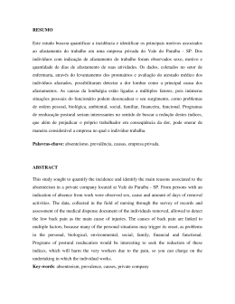
Product Bulletin FX07 Field Controller Issue Date May 5, 2011 FX07 Field Controller Using the FX Tools software package, you can program the FX07 field controller to operate a wide variety of commercial HVACR equipment; including small refrigeration compressors, close control units, packaged rooftop units, fan coil units, unit ventilators, and chilling or heating ceiling beam installations. The FX07 is a high performance field controller designed specifically for commercial Heating, Ventilating, Air Conditioning, and Refrigeration (HVACR) applications. The FX07 supports 17 physical inputs and outputs including a wide range of sensors and actuating devices. The FX07 includes an onboard real-time clock to support the start/stop scheduling of equipment, real-time based control sequences, and time stamping of events and trend records. With the optional integral user interface, you can locally monitor and adjust the FX07’s operation. The FX07 also supports a panel- or wall-mountable Medium User Interface (MUI) for remote monitoring and adjustment. The FX07 can be fitted with an N2 Open, LONWORKS®, or BACnet® communication card to integrate the controller into a compatible Building Automation System (BAS). Alternatively, the FX07 can be fitted with an RS-232C serial communication card to transmit event notification messages via Short Messaging Service (SMS) through a Global System for Mobile (GSM) modem. Figure 1: FX07 Field Controller with Integral User Interface Features and Benefits Freely Programmable Controller Is suitable for a wide range of HVAC or refrigeration control applications using the extensive programming features of the FX Tools software package. Network Communication Card Options: N2 Open, LONWORKS, and BACnet Protocols Provide cost effective solution for stand-alone or networked applications. Remote Communication Services Enable automatic reporting of events and alarms by SMS for stand-alone applications. Optional Integral Liquid Crystal Display (LCD) User Interface with Four Control Buttons Provides onboard user access to the controlled system parameters using a custom designed display with two rows of alphanumeric characters and graphic icons with backlight. Optional Remote User Interface Provides a clear presentation of control system data (including trend log data) on a menu driven and scrolling 4 line x 26 character LCD display with backlight. Continued on next page . . . © 2010 Johnson Controls, Inc. Code No. LIT-12011268 1 Features and Benefits (Cont.) Analog Outputs with Pulse Width Modulated (PWM) Option Provide an interface to a wide range of actuators and drives. Models with Various Output Configurations of Solid-State Triacs and Line Voltage Relays Provide cost effective control of refrigeration, unitary, and terminal unit equipment. Network Room Module (NRM) Features an internal temperature sensor and optional LCD display and dial, which allow the occupant to view and adjust the temperature setpoint value. Onboard Inputs and Outputs You can connect up to 17 physical inputs and outputs to the FX07, including: x four Analog Inputs (AIs) (software configurable) x x keypad with four push buttons x navigation menu to guide users The integral user interface is fully configurable within the application design and typically provides: x display of status information x display and modification of setpoints x display and modification of configuration parameters five Digital (Binary) Inputs (DIs) x clearing and acknowledgement of active alarms voltage free contacts x background lighting with red color when an alarm condition exists with pulse counter option six Digital (Binary) Outputs (DOs) (model dependent) x A99 temperature Ni 1000 (Johnson Controls) temperature Pt 1000 temperature NTC 10k temperature Ratiometric (0.5-4.5 VDC) 0-10 VDC x six relays (line voltage contacts) two triacs (24 V), three interlocked relays, one free (high power) relay two triacs (24 V), four free relays two Analog Outputs (AOs) 0-10 VDC PWM (100 Hz) Integral LCD User Interface The optional integral LCD user interface (Figure 2) for the FX07 features: x two display rows with four alphanumeric characters (13 segment) x blue or red background light x graphic status icons: compressor, alarm, high pressure, low pressure, maintenance, heat, cool, defrost, and electric heat symbols 2 FX07 Field Controller Product Bulletin Figure 2: Detail of the LCD Remote Medium User Interface BACnet MS/TP Communication Card The FX07 also supports a remote medium user interface. The MUI has a 4 line x 26 character, backlit LCD screen, 6 push buttons, and 10 discrete status Light-Emitting Diodes (LEDs). See Figure 3. You can completely configure the MUI, including its navigation menu, within the FX07 application design. The mounting styles include: When fitted with a BACnet MS/TP communication card, the FX07 can connect to a BACnet compliant BAS. This allows network access to the FX07 control system variables and parameters. The FX07 controller supports peer-to-peer communication with other controllers on the BACnet network and change-of-value reporting to monitoring stations. x RS-232C Serial Communication Card x Panel Mount: Mounts up to 3 m (9.8 ft) from the FX07 controller. The FX07 powers and operates this user interface. A flat telephone cable connects the power supply and data communications to the FX07 controller. Wall Mount: Mounts up to 300 m (984 ft) from the FX07. The wall mount user interface must be independently powered with 24 VAC. The data communication requires a 3-wire shielded cable (not provided) for the connection from the remote display to the FX07 controller. You can also panel mount this unit. When fitted with an RS-232C serial communication card, the FX07 can connect to a Global System for Mobile (GSM) modem. When an application event goes into the active or alarm state, the FX07 sends out text messages in SMS format to a prioritized list of destinations, such as to a telephone service center or directly to a mobile telephone. Real-Time Control The FX07 controller has an embedded real-time clock that supports real-time control functions such as the display of time and date on the user interface, scheduling, and event and trend management. The real-time clock continues to run for at least 10 days without power at room temperature. Scheduling Figure 3: Remote Medium User Interface Communication Card Options The FX07 can operate as a stand-alone controller, or it can be fitted with a communication card to provide various types of remote network access. The FX07 supports N2 Open, LONWORKS, BACnet Master Slave/Token-Passing (MS/TP), or RS-232C networking communication card options. N2 Open Communication Card When fitted with an N2 Open communication card, the FX07 controller can connect to the N2 bus of a compatible supervisory controller. This allows network access to its control system variables and parameters. LONWORKS Communication Card When fitted with a LONWORKS communication card, the FX07 can integrate into a LONWORKS network. This allows peer-to-peer communication with other LONWORKS compatible devices on the network and data access from a supervisory system. The real-time clock enables the time scheduling of start and stop commands and occupancy mode changes to the equipment being monitored and controlled. You can configure scheduled commands to execute on one or more days of the week. An exception day calendar allows for alternative time schedules on holidays or during special periods in the year. You can also display and edit time schedules on the integral or remote user interface. Event Management The real-time clock enables the time stamping of alarm and event records. You can configure the FX07 controller to detect and display events and alarms associated with up to 20 data points or variables in the control application. Application events indicate to users that the controlled equipment requires attention or that the controlled conditions are not within the expected limits. Examples of alarms include: x analog value is outside of a desired range x status value represents a condition that is not normal FX07 Field Controller Product Bulletin 3 You can view, acknowledge, or clear active alarms via the integral or remote user interface. You can view the event logs on the remote user interface. You can also view the event logs via a supervisory system. Trend Management The real-time clock enables the time stamping of trend records. You can configure the FX07 to record the values of up to four points at intervals between 1 minute and 1 day. You can then view the values and times on the remote user interface. Room Command Modules Two series of room command modules are available for use with the FX07 controllers: the TM Series room command modules and the network room modules. TM Series Room Command Modules Network Room Modules The NRM (Figure 5) is an intelligent device that communicates with the FX07 via the serial display bus. The NRM features an internal temperature sensor and optional LCD display and dial, which allow the occupant to view and adjust the temperature setpoint value. Certain models also have a fan button, which allows the occupant to override the speed of a threespeed fan. The override status of the fan appears on the LCD display. The NRM also enables the initiation of a temporary occupancy period (for example, at night or weekends), and you can configure the LCD to blink when the controller is not in the occupied mode. The North American NRMs have an additional button that allows you to select the units on the temperature display (°F or °C). These modules are available in the 120 x 80 mm (4.72 x 3.15 in.) enclosure. The TM Series room command module (Figure 4) features an internal temperature sensor and an optional dial that allows the occupant to adjust the temperature setpoint value or request a warmer or cooler setpoint. Certain models also have a dial to enable the occupant to override the speed of a three-speed fan. The operation of the push button and LED are configurable within the application. Typically, the push button initiates a temporary occupancy period (for example, at night or weekends), and the LED provides occupancy status indication. Figure 5: Network Room Modules (NRMs) Figure 4: TM Series Room Command Module The TM Series room command module for North America has a 120 x 80 mm (4.72 x 3.15 in.) enclosure and has dual temperature units (°F and °C). 4 FX07 Field Controller Product Bulletin FX Tools Software Use the FX Tools software suite to program, download, test, and commission the FX devices, including the FX07. The FX Tools software is available on CD in two versions: FX Tools Pro and FX Tools Express (North America only). FX Tools Pro CD includes: x FX Builder – used to program an FX07. FX Builder provides complete flexibility in programming the FX07. x FX CommPro N2 – used to download, test, and commission an FX07 on an N2 Open network x FX CommPro LON – used to download, test, and commission an FX07 on a LONWORKS network x FX CommPro BACnet software – used to download, test, and commission an FX07 on a BACnet network. x FX Builder Express (North America only) – used to select an FX07 standard application and configure it using graphical plug-ins. IMPORTANT: Use this FX07 controller only as an operating control. Where failure or malfunction of the FX07 could lead to personal injury or damage to the controlled equipment or other property, additional precautions must be designed into the control system. Incorporate and maintain other devices such as supervisory or alarm systems or safety or limit controls that are intended to warn of, or protect against, failure or malfunction of the FX07 controller. The FX Tools Express CD (North America only) does not include FX Builder. Programming Key You can download the application to the FX07 controller via a computer with FX CommPro, or via the FX Programming Key (Figure 6) (except LON versions). Figure 6: Programming Key FX07 Field Controller Product Bulletin 5 FX07 Field Controller Dimensions Figure 7: FX07 Controller Dimensions Figure 8: FX07 Controller with Display Dimensions 6 FX07 Field Controller Product Bulletin Network Room Module Dimensions Figure 9: Network Room Module Dimensions Figure 10: Network Room Module Dimensions (North America Models) FX07 Field Controller Product Bulletin 7 Ordering Codes Table 1 through Table 12 give ordering information for the FX07 Controllers, FX07 Accessories, Room Command Modules, and Configuration Software. Table 1: FX07 Controller Ordering Information (24 VAC Power Supply, without Integral Display) Product Code Number Description LP-FX07D00-000C FX07 Controller: 4 AIs, 5 DIs, 2 AOs (0-10 V or PWM), 6 DOs (Relays), no communication card LP-FX07D01-000C FX07 Controller: 4 AIs, 5 DIs, 2 AOs (0-10 V or PWM), 6 DOs (Relays), N2 Open card LP-FX07D02-000C FX07 Controller: 4 AIs, 5 DIs, 2 AOs (0-10 V or PWM), 6 DOs (Relays), LONWORKS card LP-FX07D03-000C FX07 Controller: 4 AIs, 5 DIs, 2 AOs (0-10 V or PWM), 6 DOs (Relays), RS-232C card LP-FX07D04-000C FX07 (Rev. A): 4 AIs, 5 DIs, 2 AOs (0-10 V or PWM), 6 DOs (Relays), BACnet card LP-FX07D20-000C FX07 Controller: 4 AIs, 5 DIs, 2 AOs (0-10 V), 6 DOs (4 Relays, 2 Triacs), no communication card LP-FX07D21-000C FX07 Controller: 4 AIs, 5 DIs, 2 AOs (0-10 V), 6 DOs (4 Relays, 2 Triacs), N2 Open card LP-FX07D22-000C FX07 Controller: 4 AIs, 5 DIs, 2 AOs (0-10 V), 6 DOs (4 Relays, 2 Triacs), LONWORKS card LP-FX07D23-000C FX07 Controller: 4 AIs, 5 DIs, 2 AOs (0-10 V), 6 DOs (4 Relays, 2 Triacs), RS-232C card LP-FX07D24-000C FX07 (Rev. A): 4 AIs, 5 DIs, 2 AOs (0-10 V), 6 DOs (4 Relays, 2 Triacs), BACnet card LP-FX07D30-000C FX07 Controller: 4 AIs, 5 DIs, 2 AOs (0-10 V), 6 DOs (3 Interlocked Relays, 1 Free Relay, 2 Triacs), no communication card LP-FX07D31-000C FX07 Controller: 4 AIs, 5 DIs, 2 AOs (0-10 V), 6 DOs (3 Interlocked Relays, 1 Free Relay, 2 Triacs), N2 Open card LP-FX07D32-000C FX07 Controller: 4 AIs, 5 DIs, 2 AOs (0-10 V), 6 DOs (3 Interlocked Relays, 1 Free Relay, 2 Triacs), LONWORKS card LP-FX07D33-000C FX07 Controller: 4 AIs, 5 DIs, 2 AOs (0-10 V), 6 DOs (3 Interlocked Relays, 1 Free Relay, 2 Triacs) RS-232C card LP-FX07D34-000C FX07 (Rev. A): 4 AIs, 5 DIs, 2 AOs (0-10 V), 6 DOs (3 Interlocked Relays, 1 Free Relay, 2 Triacs), BACnet card Table 2: FX07 Controller Ordering Information (24 VAC Power Supply, with Integral Display) Product Code Number Description LP-FX07D50-000C FX07 Controller: 4 AIs, 5 DIs, 2 AOs (0-10 V or PWM), 6 DOs (Relays), no communication card LP-FX07D51-000C FX07 Controller: 4 AIs, 5 DIs, 2 AOs (0-10 V or PWM), 6 DOs (Relays), N2 Open card LP-FX07D52-000C FX07 Controller: 4 AIs, 5 DIs, 2 AOs (0-10 V or PWM), 6 DOs (Relays), LONWORKS card LP-FX07D53-000C FX07 Controller: 4 AIs, 5 DIs, 2 AOs (0-10 V or PWM), 6 DOs (Relays), RS-232C card LP-FX07D54-000C FX07 Controller: 4 AIs, 5 DIs, 2 AOs (0-10 V or PWM), 6 DOs (Relays), BACnet card LP-FX07D70-000C FX07 Controller: 4 AIs, 5 DIs, 2 AOs (0-10 V), 6 DOs (4 Relays, 2 Triacs), no communication card LP-FX07D71-000C FX07 Controller: 4 AIs, 5 DIs, 2 AOs (0-10 V), 6 DOs (4 Relays, 2 Triacs), N2 Open card Continued on next page . . . 8 FX07 Field Controller Product Bulletin Product Code Number (Cont.) Description LP-FX07D72-000C FX07 Controller: 4 AIs, 5 DIs, 2 AOs (0-10 V), 6 DOs (4 Relays, 2 Triacs), LONWORKS card LP-FX07D73-000C FX07 Controller: 4 AIs, 5 DIs, 2 AOs (0-10 V), 6 DOs (4 Relays, 2 Triacs), RS-232C card LP-FX07D74-000C FX07 Controller: 4 AIs, 5 DIs, 2 AOs (0-10 V), 6 DOs (4 Relays, 2 Triacs), BACnet card LP-FX07D80-000C FX07 Controller: 4 AIs, 5 DIs, 2 AOs (0-10 V), 6 DOs (3 Interlocked Relays, 1 Free Relay, 2 Triacs), no communication card LP-FX07D81-000C FX07 Controller: 4 AIs, 5 DIs, 2 AOs (0-10 V), 6 DOs (3 Interlocked Relays, 1 Free Relay, 2 Triacs), N2 Open card LP-FX07D82-000C FX07 Controller: 4 AIs, 5 DIs, 2 AOs (0-10 V), 6 DOs (3 Interlocked Relays, 1 Free Relay, 2 Triacs), LONWORKS card LP-FX07D83-000C FX07 Controller: 4 AIs, 5 DIs, 2 AOs (0-10 V), 6 DOs (3 Interlocked Relays, 1 Free Relay, 2 Triacs) RS-232C card LP-FX07D84-000C FX07 Controller: 4 AIs, 5 DIs, 2 AOs (0-10 V), 6 DOs (3 Interlocked Relays, 1 Free Relay, 2 Triacs), BACnet card Table 3: FX07 Controller Ordering Information (90 to 240 VAC Power Supply, without Integral Display, Not Available in North America) Product Code Number Description LP-FX07A00-000C FX07 Controller: 4 AIs, 5 DIs, 2 AOs (0-10 V or PWM), 6 DOs (Relays), no communication card LP-FX07A01-000C FX07 Controller: 4 AIs, 5 DIs, 2 AOs (0-10 V or PWM), 6 DOs (Relays), N2 Open card LP-FX07A02-000C FX07 Controller: 4 AIs, 5 DIs, 2 AOs (0-10 V or PWM), 6 DOs (Relays), LONWORKS card LP-FX07A03-000C FX07 Controller: 4 AIs, 5 DIs, 2 AOs (0-10 V or PWM), 6 DOs (Relays), RS-232C card LP-FX07A04-000C FX07 Controller: 4 AIs, 5 DIs, 2 AOs (0-10 V or PWM), 6 DOs (Relays), RS-232C card LP-FX07A20-000C FX07 Controller: 4 AIs, 5 DIs, 2 AOs (0-10 V), 6 DOs (4 Relays, 2 Triacs), no communication card LP-FX07A21-000C FX07 Controller: 4 AIs, 5 DIs, 2 AOs (0-10 V), 6 DOs (4 Relays, 2 Triacs), N2 Open card LP-FX07A22-000C FX07 Controller: 4 AIs, 5 DIs, 2 AOs (0-10 V), 6 DOs (4 Relays, 2 Triacs), LONWORKS card LP-FX07A23-000C FX07 Controller: 4 AIs, 5 DIs, 2 AOs (0-10 V), 6 DOs (4 Relays, 2 Triacs), RS-232C card LP-FX07A24-000C FX07 Controller: 4 AIs, 5 DIs, 2 AOs (0-10 V), 6 DOs (4 Relays, 2 Triacs), BACnet card LP-FX07A30-000C FX07 Controller: 4 AIs, 5 DIs, 2 AOs (0-10 V), 6 DOs (3 Interlocked Relays, 1 Free Relay, 2 Triacs), no communication card LP-FX07A31-000C FX07 Controller: 4 AIs, 5 DIs, 2 AOs (0-10 V), 6 DOs (3 Interlocked Relays, 1 Free Relay, 2 Triacs), N2 Open card LP-FX07A32-000C FX07 Controller: 4 AIs, 5 DIs, 2 AOs (0-10 V), 6 DOs (3 Interlocked Relays, 1 Free Relay, 2 Triacs), LONWORKS card LP-FX07A33-000C FX07 Controller: 4 AIs, 5 DIs, 2 AOs (0-10 V), 6 DOs (3 Interlocked Relays, 1 Free Relay, 2 Triacs) RS-232C card LP-FX07A34-000C FX07 Controller: 4 AIs, 5 DIs, 2 AOs (0-10 V), 6 DOs (3 Interlocked Relays, 1 Free Relay, 2 Triacs), BACnet card FX07 Field Controller Product Bulletin 9 Table 4: FX07 Controller Ordering Information (90 to 240 VAC Power Supply, with Integral Display, Not Available in North America) Product Code Number Description LP-FX07A50-000C FX07 Controller: 4 AIs, 5 DIs, 2 AOs (0-10 V or PWM), 6 DOs (Relays), no communication card LP-FX07A51-000C FX07 Controller: 4 AIs, 5 DIs, 2 AOs (0-10 V or PWM), 6 DOs (Relays), N2 Open card LP-FX07A52-000C FX07 Controller: 4 AIs, 5 DIs, 2 AOs (0-10 V or PWM), 6 DOs (Relays), LONWORKS card LP-FX07A53-000C FX07 Controller: 4 AIs, 5 DIs, 2 AOs (0-10 V or PWM), 6 DOs (Relays), RS-232C card LP-FX07A54-000C FX07 Controller: 4 AIs, 5 DIs, 2 AOs (0-10 V or PWM), 6 DOs (Relays), BACnet card LP-FX07A70-000C FX07 Controller: 4 AIs, 5 DIs, 2 AOs (0-10 V), 6 DOs (4 Relays, 2 Triacs), no communication card LP-FX07A71-000C FX07 Controller: 4 AIs, 5 DIs, 2 AOs (0-10 V), 6 DOs (4 Relays, 2 Triacs), N2 Open card LP-FX07A72-000C FX07 Controller: 4 AIs, 5 DIs, 2 AOs (0-10 V), 6 DOs (4 Relays, 2 Triacs), LONWORKS card LP-FX07A73-000C FX07 Controller: 4 AIs, 5 DIs, 2 AOs (0-10 V), 6 DOs (4 Relays, 2 Triacs), RS-232C card LP-FX07A74-000C FX07 Controller: 4 AIs, 5 DIs, 2 AOs (0-10 V), 6 DOs (4 Relays, 2 Triacs), BACnet card LP-FX07A80-000C FX07 Controller: 4 AIs, 5 DIs, 2 AOs (0-10 V), 6 DOs (3 Interlocked Relays, 1 Free Relay, 2 Triacs), no communication card LP-FX07A81-000C FX07 Controller: 4 AIs, 5 DIs, 2 AOs (0-10 V), 6 DOs (3 Interlocked Relays, 1 Free Relay, 2 Triacs), N2 Open card LP-FX07A82-000C FX07 Controller: 4 AIs, 5 DIs, 2 AOs (0-10 V), 6 DOs (3 Interlocked Relays, 1 Free Relay, 2 Triacs), LONWORKS card LP-FX07A83-000C FX07 Controller: 4 AIs, 5 DIs, 2 AOs (0-10 V), 6 DOs (3 Interlocked Relays, 1 Free Relay, 2 Triacs) RS-232C card LP-FX07A84-000C FX07 Controller: 4 AIs, 5 DIs, 2 AOs (0-10 V), 6 DOs (3 Interlocked Relays, 1 Free Relay, 2 Triacs), BACnet card Table 5: FX07 Communication Card Ordering Information Product Code Number Description LP-NET071-000C N2 Open communication card for FX07 LP-NET072-000C LONWORKS communication card for FX07 LP-NET073-000C RS-232C communication card for FX07 LP-NET074-000C BACnet communication card for FX07 Rev. A only Table 6: FX07 Accessories Ordering Information Product Code Number Description LP-KIT100-000C FX Programming Key DT-9100-8901 Power Supply Adapter for Programming Key: 230 VAC/12 VDC (Europe Only) LP-KIT007-001C Interface cable for standard landline modem, 1.5 m (4.9 ft) LP-KIT007-002C Interface cable for GSM modem, 1.5 m (4.9 ft) LP-KIT007-013C Null modem cable for computer connection, 3 m (9.8 ft) LP-KIT007-014C Null modem cable for computer connection, 15 m (49.2 ft) Continued on next page . . . 10 FX07 Field Controller Product Bulletin Product Code Number (Cont.) Description LP-KIT200-000C N2 Commissioning Adapter: Includes port powered RS-232C to RS-485 converter, 3 m (10 ft) cable, and mating connectors for FX05, FX06, FX07, FX14, FX15, FX16, and FXVMA. LP-KIT204-000C BACnet Internet Protocol (IP) to MS/TP Adapter: Includes USB port powered Ethernet (IP) to RS485 (MS/TP) converter, 3 m (10 ft) cable, and mating connectors for FX07, FX14, and FX16 controllers. IU-9100-8401 Converter RS-232C/RS-485 (N2) 230 VAC (Europe only) LP-KIT007-020C Bag of replacement communication wiring connectors. LP-KIT007-100C Bag of replacement Input/Output (I/O) and power wiring connectors. Table 7: TM Series Room Command Modules Ordering Information (80 x 80 mm [3.15 x 3.15 in.], °C, European Models) Product Code Number Description TM-2140-0000 Room Command Module, temperature sensor only TM-2150-0000 Room Command Module, occupancy button and LED TM-2160-0000 Room Command Module, 12-28°C setpoint dial, occupancy button and LED TM-2160-0002 Room Command Module, 12-28°C setpoint dial, occupancy button and LED, fan speed override TM-2160-0005 Room Command Module, ± setpoint dial, occupancy button and LED TM-2160-0007 Room Command Module, ± setpoint dial, occupancy button and LED, fan speed override TM-2190-0000 Room Command Module, 12-28°C setpoint dial TM-2190-0005 Room Command Module, ± setpoint dial Table 8: Network Room Modules Ordering Information (Available in Europe) Product Code LP-NRM001-000C LP-NRM002-000C Features/Options Size (mm) Service Port Type LCD Display Temperature Adjustment Dial Fan Speed Selector Button °F/°C Button Addressable 80 x 80 Program Key No No No No No Yes Yes No No No Yes Yes Yes No No LP-NRM003-000C No No No No Yes LP-NRM502-000C Yes Yes No No No LP-NRM503-000C Yes Yes Yes No No LP-NRM511-000C MUI FX07 Field Controller Product Bulletin 11 Table 9: Software Ordering Information Product Code Number Description LP-FXTPRO-0 FX Tools Pro CD (Includes the FX Builder, FX Builder Express, FX CommPro N2, LON, BACnet Software) - New User LP-FXTPRO-6 FX Tools Pro CD (Includes the FX Builder, FX Builder Express, FX CommPro N2, LON, BACnet Software) - Upgrade Table 10: TM Series Room Command Modules Ordering Information (120 x 80 mm [4.72 x 3.15 in.], °F/°C) Product Code Number Description TM-2141-0000 Room Command Module, temperature sensor only TM-2151-0000 Room Command Module, occupancy button and LED TM-2161-0000 Room Command Module, 54-82°F/12-28°C setpoint dial, occupancy button and LED TM-2161-0002 Room Command Module, 54-82°F/12-28°C setpoint dial, occupancy button and LED, fan speed override TM-2161-0005 Room Command Module, ± setpoint dial, occupancy button and LED TM-2161-0007 Room Command Module, ± setpoint dial, occupancy button and LED, fan speed override TM-2191-0000 Room Command Module, 54-82°F/12-28°C setpoint dial TM-2191-0005 Room Command Module, ± setpoint dial Table 11: Network Room Modules Ordering Information (Available in North America) Product Code LP-NRM511-000C LP-NRM552-000C LP-NRM553-000C LP-NRM611-000C LP-NRM652-000C LP-NRM653-000C Features/Options Size, mm (inch) Service Port Type LCD Display Temperature Adjustment Dial 80 x 80 (3.15 x 3.15 in.) MUI No No No No Yes Yes Yes No Yes No Yes Yes Yes Yes No 120 x 80 (4.72 x 3.15 in.) MUI No No No No Yes Yes Yes No Yes No Yes Yes Yes Yes No Fan Speed Selector Button °F/°C Button Addressable Table 12: Medium User Interfaces Ordering Information Product Code Number Description LP-DIS60P20-0C Medium User Interface (non-isolated version); can be mounted up to 3 m (9.8 ft) from the FX07 and includes panel mounting hardware. LP-DIS60P21-0C Medium User Interface (isolated version); can be mounted up to 300 m (1,000 ft) from the FX07 and includes panel and wall mounting hardware. LP-KIT007-000C Link cable for the connection of the FX07 to the panel mount MUI – 3 m (9.8 ft). 12 FX07 Field Controller Product Bulletin Technical Specifications Table 13: FX07 Field Controller Technical Specifications (Part 1 of 3) Product Codes Power Requirements Power Consumption Housing Material Protection Class Dimensions (H x W x D) Ambient Operating Conditions Ambient Storage Conditions Real-Time Clock LP-FX07xxx-xxx LP-FX07Dxx-xxx: 24 VAC/DC ±15%, 50/60 Hz – Safety Extra-Low Voltage (SELV) (Europe) – Class 2 North America LP-FX07Axx-xxx: 90 to 240 VAC, 50/60 Hz (Not available in North America) LP-FX07Dxx-xxx: 9 VA maximum LP-FX07Axx-xxx: 17 VA maximum ABS + polycarbonate, self-extinguishing: UL 94-V0 flammability rating IP20 CEI/EN60529 145 (including terminals) x 108 x 49 mm (62 mm with integral display) 5.71 (including terminals) x 4.26 x 1.93 in. (2.45 in. with integral display) -40 to 50°C (-40 to 122°F), 10 to 95% RH (noncondensing) Note that the integral user interface does not operate below -20°C (-4°F). -40 to 70°C (-40 to 158°F) 10 to 95% RH (noncondensing) Accuracy: Better than ±200 ms per day at constant ambient temperature of 25°C Backup: Minimum 10 days without power at 25°C Power Supply for Panel Mount MUI 15 VDC on remote display connector at 100 mA maximum Power Supply Outputs for AIs 15 VDC 20 mA power supply for active sensors (also used for Pulse Width Modulation [PWM] outputs) 5 VDC 15 mA power supply for ratiometric sensors 16-bit resolution – not isolated Analog Inputs Sensor Type Full Linearization Range Accuracy at 20°C (68°F) Ambient (Sensor Accuracy Not Included) A99 -50 to 100°C (-58 to 212°F) ±0.5°C (±1°F) NTC 10k -40 to 150°C (-40 to 300°F) ±0.5°C (±1°F) Pt 1000 Extended -50 to 160°C (-58 to 320°F) ±0.5°C (±1°F) Ni 1000 (Johnson Controls) Active Voltage -45 to 120°C (-49 to 248°F) ±0.5°C (±1°F) 0-10 VDC ±0.05 VDC Active Ratiometric 0.5-4.5 VDC ±0.05 VDC Display Range and Resolution -999 to 999 or -99.9 to 99.9 Digital (Binary) Inputs Voltage free contacts Transition counter function at 50 Hz (minimum 10 ms ON and minimum 10 ms OFF) Analog Outputs 0-10 VDC, maximum 3 mA, 13-bit resolution not isolated, accuracy ±0.1 VDC For actuating and control devices PWM output at 100 Hz cycle frequency with 10 mA sink from 15 VDC reference power source For fan speed controllers with PWM input Continued on next page . . . FX07 Field Controller Product Bulletin 13 FX07 Field Controller Technical Specifications (Part 2 of 3) Relay Outputs Dielectric test voltage on open relay contact: 1,000 VAC Root Mean Square (RMS) Maximum relay switching rate at maximum load: six operations per minute Average relay contact life: 30,000 operations at maximum load Digital (Binary) Outputs for Specific Models Model Channel Type Remark/Application FX07D0x-xxx FX07D5x-xxx FX07A0x-xxx FX07A5x-xxx DO1, DO2, DO3 Single-Pole, Single-Throw (SPST) 5(3) A, 250 VAC relay Maximum 24 VAC in North America) Each relay contact is independent with its own common terminal. DO4, DO5, DO6 SPST 3(1) A, 250 VAC relay Each relay contact is independent with its own common terminal. Motor: 0.1 hp, 230 VAC, 0.05 hp, 120 VAC FX07D2x-xxx FX07D3x-xxx FX07D7x-xxx FX07D8x-xxx DO1, DO2 0.5 A/24 VAC triacs Low voltage 3-point incremental actuators, thermal actuators, for example FX07A2x-xxx FX07A3x-xxx FX07A7x-xxx FX07A8x-xxx DO1, DO2 0.5A/250 VAC triacs Line voltage 3-point incremental actuators, thermal actuators, for example Can also be used to switch low-voltage 24 VAC devices. FX07D2x-xxx FX07D3x-xxx FX07D7x-xxx FX07D8x-xxx FX07A2x-xxx FX07A3x-xxx FX07A7x-xxx FX07A8x-xxx DO3 SPST 5(3) A, 250 VAC relay (Maximum 24 VAC in North America) Relay contact is independent with its own common terminal. DO4 – DO6 SPST 3(1) A, 250 VAC relay On the FX07x2x-xxx and FX07x7-xxx models, each relay contact is independent with its own common terminal. On the FX07x3x-xxx and FX07x8-xxx models, DO4, DO5, DO6 relays are physically interlocked so that only one output is closed at one time. Application: 3-speed fan motors. Motor: 0.1 hp, 230 VAC, 0.05 hp, 120 VAC Connection for Outputs and Power Connection for Inputs and LON/ N2Open/BACnet Networks BACnet Compliance 2 Screw terminals for maximum 2 x 1.5 mm (16 AWG) wires, included in the package 2 Screw terminals for maximum 1 x 1.5 mm (16 AWG) wires or 2 x Belden® cable, 2-core twisted pair with shield 0.8 mm (20 AWG), included in the package. BACnet Testing Laboratories™ (BTL) Listing BACnet Interoperability Building Blocks (BIBBs): BACnet Advanced Application Controller (B-AAC) Protocol Implementation Conformance Statement (PICS) available on request Continued on next page . . . 14 FX07 Field Controller Product Bulletin FX07 Field Controller Technical Specifications (Part 3 of 3) Agency Compliance Europe (all models) – 2004/108/EEC, EMC Directive: EN 61000-6-3, EN 61000-6-2 – 2006/95/EEC, Low Voltage Directive: EN 60730 Canada (LP-FX07Dxx-xxx models only) – UL Listed (PAZX7), C22.2 No. 205, Signal Equipment – Industry Canada, ICES-003 United States (LP-FX07Dxx-xxx models only) – UL Listed (PAZX), UL 916, Energy Management Equipment – FCC compliant to CFR 47, Part 15, Subpart B, Class A The performance specifications are nominal and conform to acceptable industry standards. For application at conditions beyond these specifications, consult the local Johnson Controls office. Johnson Controls, Inc. shall not be liable for damages resulting from misapplication or misuse of its products. Building Efficiency 507 E. Michigan Street, Milwaukee, WI 53202 Johnson Controls® is a registered trademark of Johnson Controls, Inc. All other marks herein are the marks of their respective owners. © 2011 Johnson Controls, Inc. FX07 Field Controller Product Bulletin 15
Baixar