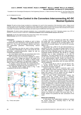
Federal University of Santa Catarina - UFSC
Post-graduation in Electrical Engineering - PPGEEL
Power Electronics Institute - INEP
Master Thesis Presentation:
Study and Design of a Voltage Line Conditioner
with Serial Compensation and Fed by Load Side
Eng. MSc Thiago Batista Soeiro
July, 2007
Presentation Contents
• Introduction
• Voltage Line Conditioner: Power Stage
• Voltage Line Conditioner: Control Stage
• Experimental Results
• Conclusions
Motivations
1- The increase of voltage-sensitive equipments results in greater
demand for high-quality voltage sources;
2- The existence of standards limiting the harmonic pollution in
electric power system;
3- To aid the national industries in the development of high-quality
voltage sources.
Main Objectives
1- To study concepts and topologies of voltage line conditioners;
2- To establish general voltage compensation methods to be applied
in voltage line conditioners;
3- To evaluate the performance of the topology proposed under
unbalanced and distorted system voltages;
4- To study and formulate control techniques to provide the
conditioning of the load voltage
5- To develop and test a voltage line conditioner prototype to
validate the analysis.
Important Concepts
io
The Studied Topology was based on two
+
concepts:
ZL
d
− vri +
vi
• The Principle of Serial Voltage
Compensation, applied in Stabilizers in
1950 by Patchett
vo ( vi , io , d )
−
−
vr
Lo
Rectifier
S1
S2
S3
+
• Indirect ac-ac Converter with
Direct link presented by BongHwan Kwon in 2002
+
vri
vri
−
S5
S7
a
S4
S6
b
S8
Inverter
− vds
vdp
Co
+
Important Concepts
The Voltage Line Conditioner Operation Principle:
vi′
+
=
vds
−
vds = vdsF + vdsH
vo
+
io = iF + iH
ZS
vi = vF + vH
vo
vi′
− vri +
Voltage Line Conditioner
Generalization of Serial Voltage Conditioners:
• The Serial Voltage Compensation:
−Δv +
+
vo
−
+
+
vo
vi
−
Conversor
ca − ca
Direct Compensation
Carga
Conversor
Conversor
CA-CA
ca − ca
Inversor
Carga
−
− Δv
+
+
vi
Transf. + Filter
−
Voltage Line Conditioner
− Δv
Filter by the load side
+
− Δv
Conversor
Conversor
CA-CA
ca − ca
Inversor
Transf. + Filter
−
+
+
vo
vi
−
Conversor
Conversor
CA-CA
ca − ca
Inversor
−
Carga
vo
vi
Carga
+
+
−
+
Voltage Line Conditioner
• Feeding the ac-ac Converter:
Conversor
Compensador
CA-CA
sérieInversor
By the Load Side
Conversor
Compensador
CA-CA
sérieInversor
vo
vi
−
−
+
vi
−
By the Line Side
+
vo
Carga
+
Carga
+
−
Voltage Line Conditioner
Conversor
Compensador
CA-CA
sérieInversor
vo
−
+
vi
vaux −
Auxiliary Source
Carga
+
+
−
Voltage Line Conditioner
• ac-ac Converter Isolation:
+
− vds
+
Co
T1
+
vf
−
vi
+
Lo
Converter
ac − ac
vo
Inverter
By the
Rectifier side
−
−
−
+
By the
inverter side
vi
−
vds
Co
+
vf
−
Conversor
Converter
ac − ac
CA-CA
Retificador
T1
Lo
+
+
vo
Inversor
Inverter
−
Voltage Line Conditioner
• Conditioner Topologies:
− vds
+
vi
+
Co
+
vf
−
Lo
T1
Conversor
Converter
vo vi
vf
−
vo
Co
Retificador
Inverter
− −
−
− vds +
vi
+
Lo
ac − ac
CA-CA
Inversor
Inversor
Inverter
−
+
vds +
T1
+ +
Conversor
Converter
ac − ac
CA-CA
Retificador
−
Co
T1
+
vf
−
Lo
−
T1
+ +
Conversor
Converter
Converter
ac − ac
vo vi
vds +
vf
ac − ac
CA-CA
In verso r
Inverter
− −
Fed by the line side
+
Lo
Co
vo
Retificador
Inverter
−
Voltage Line Conditioner
• Conditioner Topologies:
−
vds +
−
T1
+
Lo
Conversor
Converter
ac − ac
CA-CA
Inversor
vf
Co
i
Inversor
vo
vf
Retificador
Inverter
−−
−
vds
−
−
+
Co
Lo
T1
+
Conversor
Converter
ac − ac
CA-CA
Inversor
−
Conversor
Converter
ac − ac
CA-CA
Retificador
Inverter
−
vi
+
Lo
vov
Co
+
T1
++
vi
+
vds
vf
vo
+
vds +
Co
vi
Retificador
Inverter
Lo
Conversor
Converter
ac − ac
CA-CA
Inversor
−
−
Fed by the load side
T1
vf
+
vo
Retificador
Inverter
−
Voltage Line Conditioner
• Conditioner Topologies:
−
vds +
T1
+
Conversor
Converter
vi
vf
Co
vo
−
−
Conversor
Converter
ac − ac
CA-CA
Inversor
vi
+
vf
−
Lo
Co
vo
ac − ac
CA-CA
R etificador
vo
Inversor
Inverter
−
−
+
vi
Retificador
Inverter
−
+
Lo
T1
Conversor
Converter
− vds
+
+
Co
vds +
T1
+
vf
+
Retificador
Inverter
−
−
+
Lo
ac − ac
CA-CA
In verso r
vi
− vds
Co
T1
+
vf
−
Lo
+
+
Conversor
Converter
ac − ac
CA-CA
Retificador
−
Fed by an auxiliary source
vo
Inversor
Inverter
−
Voltage Line Conditioner:
Power Stage
−
vds
LS + Lds
+
T1
io
+
vi
Lo
+
S5
iLo
S7
S3
S1
b vr
a
S6
S8
Co
S4
vo
S2
−
−
Inverter
Rectifier
Modulation Strategy
v0 (t )
PWM Inverter (S5 - S8)
S1,4 (t )
S 2,3 (t )
vr (t)
0
Tr
2
Tr
Bidirectional Rectifier (S1 - S4)
t
Main Waveforms
Adding voltage
vi
vo
3 Level PWM Modulation
Subtracting voltage
Rectifier input voltage
Rectifier input voltage
vg1,4
vg 2,3
vr
Rectifier
vc
vab
Inverter
0
vds
d⋅
Ts
2
Ts
2
vo
vi
t
0
π
2π
t
0
π
2π
Main Analytical Expression
N
g (t ) =
N − d (t )
1
N = ⋅ d (t )
Δ
ΔI Leq =
ΔVCo =
Converter’s Static Gain
Transformation ratio
V0 ⋅ d ( t ) ⋅ (1 − d ( t ) )
2 ⋅ N ⋅ f s ⋅ Leq
ΔI Leq ⋅ ( N − d ( t ) )
16 ⋅ N ⋅ f S ⋅ Co
+
Current ripple
I o 2 ⋅ d ( t ) ⋅ (1 − d ( t ) )
4 ⋅ f S ⋅ Co ⋅ ΔI Leq ⋅ ( N − d ( t ) ) ⋅ ( N − 1)
Voltage ripple
Voltage Line Conditioner:
Control Stage
LS
LdP
S5
S7
S3
S1
vi ()
t
C0
S6
S8
S4
Sensor
de
Tensão
S1 S2 S3 S4
vSrr
vSrr
Modulador
Cv (s)
Modulador
v0(t)
S2
Comando
S5 S6 S7 S8
Carga
Rede de Energia
RS
vo _ ref
−
+
Compensador de Tensão
Mathematical Model
• Small signals model:
• G(s), Transfer Function of output voltage vs. duty cycle;
• F(s), Transfer Function of output voltage vs. input voltage .
v0 ( s ) = F ( s ) ⋅ vi ( s ) + G ( s ) ⋅ d ( s )
vlo
G (s) = =
d
vlo
F (s) = =
vl
i
− s ⋅ Leq ⋅ N 2 ⋅ Vo
ZL ⋅ ( N − D)
s ⋅ Leq ⋅ Co ⋅ N +
2
2
+ Vo ⋅ ( N − D )
s ⋅ Leq ⋅ N 2
ZL
N ⋅( N − D)
s ⋅ Leq ⋅ Co ⋅ N +
2
2
s ⋅ Leq ⋅ N 2
ZL
+ ( N − D)
+ ( N − D)
2
2
Conditioner Analytical Study
• Load Influence over circuit’s dynamic response:
Conditioner Analytical Study
There are some strategies to damp the voltage oscillation or compensate the
absence of load:
• To damp voltage oscillation with virtual resistance control strategy;
• To insert a control loop to compensate abrupt voltage drop;
• To insert input filter topologies;
Virtual Resistance
Line conditioner Block Diagram:
N ⋅ RVirtual
V0 ⋅ GPWM
N −D
N
iˆ0
Vc ( s ) −
+
Gd̂PWM
d̂
−
Vo
N
+
vˆLeq
−
+
vˆi
iˆLeq
1
s ⋅ Leq
+
D
N
RVirtual
Vo
ZL ⋅( N −D)
−
+
+
−
iˆCo
1
sC0
v̂0
Converter Control
RS
LS
LdP
D5
S7
S6
Sensor
de
Corrente
S3
D 3 S1
D1
a
b
vi ()
t
D7
D6
S8
C0
D8
S4
D4
S2
v0(t)
D2
Sensor
de
Tensão
Comando
S1 S2 S3 S4
S5 S6 S7 S8
Modulador
+
vSrr
vSrr
Carga
S5
−
Modulador
Cv (s)
vo _ ref
−
+
+
+
Compensador de Tensão
C Rv ( s )
−
+
Rede de Energia
T
Compensador de Rvirtual
Ic ( s )
Experimental Results
Prototype
Vi = 220 ± 20% [ V ]
Vo = 220 [ V ]
So = 10 [ kVA ]
Fr = 60 [ Hz ]
FS = 20 [ kHz ]
N =4
Leq ≈ 340 [ μ H ]
Co = 20 [ μ F]
Control Signals
ac-ac converter voltage signals
Rectifier
Inverter
Operation with Load Transient
Without Virtual Resistance Control Loop
With Virtual Resistance Control Loop
50% Load Transient
Operation with input Transient
• +20% transient in input voltage Vi(t):
Operation with input Transient
• -20% transient in input voltage Vi(t):.
):
Operation with input Transient
• THD correction:
Nonlinear load Operation
The greatest requirements in terms of dynamic
response.
+
100 μ H
10Ω
vo
−
10 mF
Conclusions
• Experimental Results:
• The control strategy was efficient with instantaneous correction of the output
voltage when faced with input voltage and load variations;
• Capability of supplying an output voltage with low harmonic distortion;
• When presented with the worst case scenario, a nonlinear load, the conditioner
studied was able to correct the THD to fit the required standards of 5%
(IEEE519/92);
Conclusions
• Contributions:
• A generalization of serial line conditioners was presented through 12 possible
topologies;
• This work focused on the study of a serial line conditioner with an ac-ac indirect
converter with direct link, fed by load side. The capacitive filter was positioned on the
load side to make use of the line impedance as a multi-functional filter;
• A control strategy was introduced to efficiently stabilize the output voltage of the
studied structure;
.
Conclusions
• Future works:
• Study of three-phase voltage line conditioners:
- Space vector Modulation;
- Digital Control and Nonlinear Control Techniques;
- Study of Rectifier control techniques;
- Study of combined series and shunt active power filters for
simultaneous compensation of voltage and current;
- Hybrid and Matrix Converters;
The End
Baixar