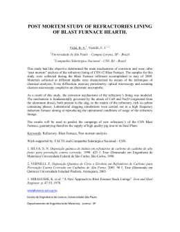
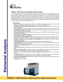
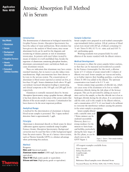
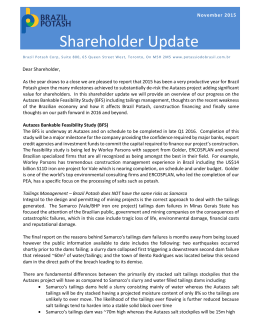
a
http://dx.doi.org/10.4322/tmm.2014.048
Artigo Original
AVALIAÇÃO DA DISTRIBUIÇÃO DE GASES EM FORNO DE
PELOTIZAÇÃO DA SAMARCO MINERAÇÃO ATRAVÉS
DE CFD E VALIDAÇÃO EXPERIMENTAL
Maycon Athayde 1
Roberto Parreiras Tavares 2
Sergio Fernando Nunes 3
Maurício Cota Fonseca 4
Resumo
A Samarco Mineração produz pelotas de minério de ferro processadas termicamente em fornos de grelha móvel.
Este processo é fundamental para que se obtenha a adequada resistência mecânica dos aglomerados para o transporte
e operação dos reatores de redução. Todas as propriedades mecânicas dos aglomerados são obtidas durante a etapa
de queima, sendo etapa decisiva, para a qualidade da pelota. Portanto, a distribuição de velocidade do fluxo gasoso no
interior desta zona deve ser homogênea ao longo do leito. Para tanto, foi desenvolvido um modelo matemático em CFD
objetivando caracterizar o escoamento dos gases na zona de queima, aplicando as equações de conservação de quantidade
de movimento, massa e energia. A validação do modelo proposto foi obtida através de medições de temperaturas no
interior do forno. Foi desenvolvido um sistema de comunicação wireless de forma a acompanhar de forma contínua a
evolução de temperatura do forno.
Palavras-chave: Modelagem; CFD; Pelotização; Leitos porosos.
EVALUATION OF FLOW DISTRIBUTION IN THE PELLETIZING FURNACE
THROUGH CFD AND EXPERIMENTAL VALIDATION AT SAMARCO
Abstract
Samarco produces iron ore pellets thermally processed in Travelling Grate furnaces. This process is essential in
order to obtain adequate mechanical strength to the pellets transportation and operation in the reduction reactors. All the
mechanical properties of the agglomerates are obtained during the stage of firing, being a decisive step to pellet quality.
Therefore, the velocity distribution of gas flow within this zone must be homogeneous. For this reason, it was developed
a mathematical CFD model to characterize the gas flow in the burning zone, applying the equations of conservation of
momentum, mass and energy. The validation of the model was obtained by measuring the temperatures inside the furnace.
It was developed a wireless communication system in order to monitor continuously the evolution of the temperatures
in the furnace.
Keywords: Modeling; CFD; Pelletizing; Packed beds.
1 INTRODUCTION
One of the strategic objects of Samarco Mineração
S/A is to “ensure quality products and services”. The iron
ore pellet quality is attained when mechanical resistance
is added to the agglomerates. This property is obtained
by thermal treatment of the pellets in the Travelling Grate
furnace. In order to achieve this goal, the furnace processes
the pellets in three steps: drying, firing and cooling. Accor-
ding to Meyer [1], all properties of the agglomerates are
obtained during firing, and therefore this step is crucial to
ensure the quality of the pellet.
Travelling Grate furnaces are thermal equipment
based on intense heat transport by convection. Through
recovery of the heated air due to the cooling of the pellets
at the discharge of the furnace, firing of the new agglome-
Metallurgical Engineer, Process Engineer, Samarco Mineração S/A, Anchieta, ES, Brasil. E-mail: [email protected]
Metallurgical Engineer, Professor, Universidade Federal de Minas Gerais – UFMG, Belo Horizonte, MG, Brasil. E-mail: [email protected]
3
Metallurgical Engineer, Process Specialist, Samarco Mineração S/A, Anchieta, ES, Brasil. E-mail: [email protected]
4
Metallurgical Engineer, Technology Specialist, Samarco Mineração S/A, Anchieta, ES, Brasil. E-mail: [email protected]
1
2
340
Tecnol. Metal. Mater. Miner., São Paulo, v. 11, n. 4, p.340-345, out./dez. 2014
Avaliação da distribuição de gases em forno de pelotização da Samarco Mineração através de CFD e validação experimental
rates is performed by adding heat to the pre-heated air
via burners positioned along the firing zone. Despite the
importance for the quality of the product, thermocouples
placed above the pellet bed indicated unbalanced gas flow
along the firing zone. Additionally, thermographic images
of the furnace discharge have shown a large temperature
variation along the bed cross section. Uneven gas flow
distribution may lead to higher variability of the final physical
quality of the agglomerates.
The decrease of pellet quality increases the risk of
degradation during transport [2]. Additionally, in industrial
practice, the irregular hot gas flow distribution along the
cross section of the furnace may generate premature and
non-uniform mechanical parts wearing especially in the
firing zone where the highest temperature occur. Despite
the high temperature of the process and the process air
rate that can be higher than 1500 Nm³/dmt, the dominant
mechanism for energy transport is convection, different
from other industrial and common pellet beds where
radiation is more important.
Fluid dynamic and geometric factors may be associated with non-regular profile of the heated gas flow, which
is unwanted to the process. The geometric asymmetry of
furnace windboxes, which conduct the gas flow from the
firing zone to the exhaust fan, seems also to be critical and
is also pointed out as the reason of the preferential wearing
of the pallet car at the south side.
2 MATERIALS AND METHODS
2.1 Mathematical Modeling of Flow in the Burning
Zone
A numerical code based on finite elements method
was applied [3] for solving continuity and Average Reynolds
Navier-Stokes equations (RANS). The energy conservation
equation was also included in the model. The study was
conducted with resources from LaSiP - Process Simulation
Laboratory, in the Department of Metallurgical and Materials Engineering of the Engineering School at UFMG. The
discretization of the fluid domain was carried out through
a mesh of 118,225 elements (the mesh independence test
showed less than 2% variation doubling the number of
elements, which was considered acceptable). Regarding
the boundary conditions, the combustion was taken into
account based on the assumption of non-reactive approach
injecting a stream of combustion products (CO2, H2O, N2
and O2) at the adiabatic flame temperature, considering a
multicomponent flow. The pressure at the windbox outlet
was set up as the static pressure measured in the pellet
plant and the furnace walls were considered adiabatic. The
flow regime was considered permanent. This latter simplification was assumed to minimize the computational cost
due to the high mesh refinement achieved. It may fit the
industrial practice as the gas flow is roughly fully developed
crossing the pellet beds, however, the pellet bed movement
is transient regarding the furnace production line. This
assumption is valid considering the purpose of the present
work which is the evaluation of the flow profile of the gases
(many studies have evaluated the pellet bed temperature
profile after Thurlby et al. [4]). The κ-ε model turbulence
was used. This model is largely used in industrial cases according to Seshadri et al. [5]. One more assumption needed
to the travelling grate furnace is the effect that the porous
bed on the pressure drop of the fluid through the furnace.
This effect may be modelled adding a source term on the
momentum equations. This source term can be defined
by Equation 1 which is similarly to the Ergun’s equation for
pressure drop in the particle bed [6].
∂p
=
∂xi
µ
ρ
Ui + Kloss
Ui U (1)
Kperm
2
1
ϕd²
Where, Kperm =
150 (1− ε ) ² 1
( ε)
3
and Kloss = 1,75
(1− ε ) (1ε 3 )
ϕd
.
µ: Dynamic Viscosity (kg/m.s); ρ: fluid density (Kg/m³);
ϕ: Roundness (-); ε: void fraction; U: Fluid Velocity (m/s)
2.2 Development of Temperature Measurement
System in Pallet Cars
It was developed in partnership with INSAUT
Instrumentation a continuous and on-line measurement
system for temperature profile of the pallet cars along
the furnace to evaluate for a long term the temperature
profile of the pellets and grate bars. Grate bars with points
for insertion and support of thermocouples were used.
In order to establish a system for data communication,
temperature transmitters and signal repeaters composed a
wireless HART network, non-structured. In this developed
device, the signal is constantly optimized as the network
tries to communicate the temperature information. This
system enables to determine the location of the pallet
car across the furnace. The whole system consists in
15 signal repeaters, which can communicate with each
other in order to amplify and ensure the highest possible
signal strength for the network. The reception of these
signals from the repeaters strategically positioned along
the furnace was carried out through a gateway positioned
on the side of the furnace with the function of sending the
signal to the record data system for remotely monitor
the process. Every four thermocouples installed in the
pallet cars operate in groups of temperature transmitters
that had the communication function, the wireless HART
network, yet transmitter electronic temperature was also
monitored, creating a safety parameter for the equipment
integrity.
Tecnol. Metal. Mater. Miner., São Paulo, v. 11, n. 4, p.340-345, out./dez. 2014
341
Athayde et al.
3 RESULTS AND DISCUSSION
3.1 Characterization of the Fluid Flow in the Firing
Zone
Figure 1 shows the velocity and the flow pattern
of the gases in the region of the firing zone. The velocity
contours show the existence of areas with high velocities,
especially close to the grate bars and burner.
Figure 1. Velocity contours inside the firing furnace zone.
This map also highlights the effect on the inlet flow
from the burner of the downcomer, which generates a
deflection of the flames leading to a change in velocity
pattern inside the combustion chamber. That seems to
influence the entire velocity profile in the firing zone of
the furnace. According to Athayde et al. [7], this effect can
increase the risk of obstruction of the combustion chamber
due to accumulation of particles carried out through the
downcomers to the combustion chamber bottom.
The flame deflection occurs in the combustion
chamber due to the ratio between the cross momentum
flow rates of the air stream and natural gas coming out of
the burner. Figure 2 shows a front view of the combustion
chamber where the configuration of the flame is captured
in four moments. As shown, the “tail” of the flame is always
displaced downwards, as predicted by the model.
In the present work, it has been identified that the
high jet velocity from the burner is intensely deflected by
the flow coming from the downcomers, even after the
combustion chamber length. Afterwards, the flow goes
towards the pellet bed with higher intensity near the sides
of the furnace, and not in the center, as expected. One
possible cause for this effect might be the differences in
the void fraction between pellet bed and the hearth layers,
which has great impact on the flow pattern. A simulation
carried out, shown in Figure 3, shows the influence of the
void fraction in the pressure drop across the pellet bed.
This influence is more significant than the increase of the
pellet mean size. Indeed, the amount of voids between the
pellets seems to be more critical and it is strongly linked
to the heterogeneity of particle size distribution. At this
Figure 2. Flame deflection inside the combustion chamber.
342
Tecnol. Metal. Mater. Miner., São Paulo, v. 11, n. 4, p.340-345, out./dez. 2014
Avaliação da distribuição de gases em forno de pelotização da Samarco Mineração através de CFD e validação experimental
point it is important to highlight that the small pellets are
screened out of the hearth layer (burned pellets) in order
to attain better gas flow into the bottom hearth layer of
the pallet car. A pressure drop of 400 mmWG was found
between the hearth layer side wall of the pallet car and the
green pellet, shortcutting the gas flow closer to this region.
The non-uniform distribution of gas flow can lead to
heterogeneity of the final physical quality of the agglomerates in the central region of the furnace, as it can reduce
the residence time at certain reaction temperature, defined
by Batterham et al. [8] as the isothermal pellet trajectory.
In the industrial practice, the heat input is increased to
guarantee the quality, on another hand this may have a
side effect as this singularity along this flow pattern may
promote premature and not uniform wearing of mechanical
parts as the pallet car grate bars and side walls. It is shown
in Figure 4 an industrial example of the the side bars of the
furnace damaged due to the intense gas flow in the region
of the extremities of the pallet car.
Furthermore, other geometric factors of the furnace
can also be associated with the uneven flow distribution. For
instance, the lack of symmetry plane on the windboxes has
been pointed as a critical issue for the gas flow distribution.
It is associated with the differences between the two sides
of the furnace. It is also remarkable the higher south side
degradation compared with the north side. Although there
is a plane of symmetry in the firing zone hood, there is no
symmetry at the bottom of the pellet bed, in the windboxes.
This geometry leads to a gas flow that may cause premature
and accentuated wearing of the furnace south side or specifically the side near the outlet duct towards the exhaust fan.
Figure 3. Influence of the void fraction and divisions of the pellet
beds fall pressure in the pellet beds.
Figure 6. Example of slag reaction on the refractory due the iron
ore fine inside the furnace.
Figure 4. Abrasive wearing due to intense flow in the region.
Figure 5. Velocity profile inside the furnace highlighting the temperatures gradient.
Figure 7. Temperature Contours at the furnace cross section.
Tecnol. Metal. Mater. Miner., São Paulo, v. 11, n. 4, p.340-345, out./dez. 2014
343
Athayde et al.
Figure 8. Velocity distribution on the pellet bed, showing intensity on the grate bars.
Figure 10. Industrial Validation of the proposed model and mapping
temperatures of pallet car.
Figure 9. The concentration of water vapor along the furnace.
The most important final effect of this uneven
flow distribution was observed in the temperatures in the
furnace. Figure 5 shows the velocity profile across the
furnace. The higher velocities are further the hood furnace
centerline and similarly the high temperature streams
concentrated closer to the sidewall. This has an important
implication on the process (side hearth layer).
The main factor to determine the pressure drop in
the furnace is the pellet bed itself. A remarkable feature of
the previous map of velocity is the strong recirculation of
the gases in the central region of the furnace, which carries
iron ore fines to the hood, causing a slag reaction with the
refractory hood (Figure 6).
The resulting effect of the gas stream is previously
demonstrated directly in the temperature profile inside the
pellet bed and even on the grate bars, that, as a consequence,
will exhibit overheat and also the higher temperature cycles,
resulting in excessive abrasive wearing in this region. The
temperature profile is presented in Figure 7.
344
Figure 8 shows the combined influences of the mass
flow passing through the pellet bed and the temperature
of the grate bar. A broad distribution of flows along the
pellet beds occur and, therefore, the unbalance in the flow
of the furnace hood leads to heterogeneity in this region.
It is important to state that regions with more intense gas
flow also exhibit higher temperatures. This effect occurs
especially in the region comprised of the 8 grate bars from
the first “blind bar”, which presents excessive wear.
The flow of the combustion products coming
from the burners also concentrates near the furnace
wall (Figure 9). The multicomponent gas flow should be
analyzed. The high concentration of super-heated steam
(molar fraction from 0.04 to 0.07, at temperatures above
1,000 °C) in the region becomes a powerful agent of great
importance in the generation of wear on grate bars.
3.2 Validation of the Proposed Model and Analysis
of Temperature Measurements
Thirty days of continuous monitoring of the temperatures of the pallet car was performed in order to establish
the “burnthrough” temperature of each cycle. Figure 10
shows a Box-Plot representing the temperature distribution in the bottom layer in different pallet car positions.
Tecnol. Metal. Mater. Miner., São Paulo, v. 11, n. 4, p.340-345, out./dez. 2014
Avaliação da distribuição de gases em forno de pelotização da Samarco Mineração através de CFD e validação experimental
This figure also includes the temperatures predicted by
mathematical model. As shown, the variation is similar to
the average data measured at the end of the firing zone of
the furnace, where steady state condition is attained.
The data were collected directly on the industrial
plant and a good fit to the predicted values was obtained.
The shift between the measured and calculated curve it
is attributed to steady temperature profile achievement
within the bed pellet and to the large response time of the
thermocouples as the pallet car is suddenly cool down due
the cooling zone.
4 CONCLUSION
It was possible through a two-dimensional model to
characterize the fluid profile in a pelletizing furnace. The
model helped on the identification of an uneven velocity
and temperature profiles which may be the main cause to
the mechanical parts wearing due to the high temperatures
required in the process. A robust measurement system and
reliable temperature measurements were developed which
enabled the validation of the mathematical model.
Acknowledgements
The financial support of FAPEMIG – Fundação de
Amparo à Pesquisa do Estado de Minas Gerais, Brazil - in
the form of a research grant to R. Tavares, Process No.
PPM-00118-13, is gratefully acknowledged.
The authors also acknowledge the financial support
of CAPES/PROEX to the graduate program (PPGEM).
REFERENCES
1 Meyer K. Pelletizing of iron ores. Düsseldorf: Springer-Verlag mbH; 1980.
2 Nunes SF. Influência da carga circulante do pelotamento na qualidade física das pelotas cruas e queimadas da Samarco
Mineração [dissertação de mestrado]. Ouro Preto: Redemat/UFOP; 2007. 133 p.
3 Patankar SV. Numerical heat transfer and fluid flow. Washington: McGraw Hill Book Company; 1980.
4 Thurlby JA, Batterham RJ, Turner RE. Development and validation of a mathematical model for the moving
grate induration of iron ore pellets. International Journal of Mineral Processing. 1979;6(1):43-64. http://dx.doi.
org/10.1016/0301-7516(79)90031-0.
5 Seshadri V, Tavares RP, Silva CA, Silva IA. Fenômenos de transporte: fundamentos e aplicações nas Engenharias
Metalúrgica e de Materiais. São Paulo: ABM; 2010.
6 Niven KR. Physical insight into the Ergun and Wen & Yu equations for fluid Flow in packed and fluidised beds.
Chemical Engineering Science. 2002;57(3):527-534. http://dx.doi.org/10.1016/S0009-2509(01)00371-2.
7 Athayde M, Nunes SF, Silva GAL, Sousa FDA, Arima MN. Novel burner design supported by cfd to minimize
deposits inside combustion chambers of samarco pelletizing furnaces. In: Associação Brasileira de Metalurgia,
Materiais e Mineração – ABM. Anais do 6th International Congress on the Science and Technology of Ironmaking;
2012; Rio de Janeiro, Brasil. São Paulo: ABM; 2012. p. 100-105.
8 Batterham RJ. Modeling the development of strength in pellets. Metallurgical and Materials Transactions. B, Process
Metallurgy and Materials Processing Science. 1986;17(3):479-485.
Received: 11 June 2014
Accepted: 15 Oct. 2014
Tecnol. Metal. Mater. Miner., São Paulo, v. 11, n. 4, p.340-345, out./dez. 2014
345
Baixar