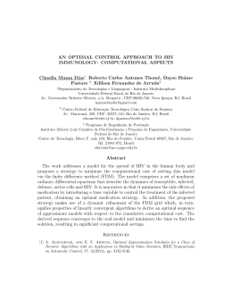
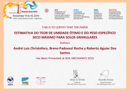
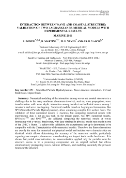
Computational modeling applied to the study of wave energy converters (WEC) Flávio Medeiros Seibt1, Max Letzow1, Mateus das Neves Gomes2,3, Jeferson Avila Souza1,4, Luiz Alberto Oliveira Rocha1,3,4, Elizaldo Domingues dos Santos1,4 and Liércio André Isoldi1,4,* 1 Programa de Pós-Graduação em Engenharia Oceânica (PPGEO) - Escola de Engenharia (EE), Universidade Federal do Rio Grande (FURG), Av. Itália km 8, CEP 96203-900, Rio Grande-RS, Brazil. 2 Instituto Federal de Educação, Ciência e Tecnologia do Paraná (IFPR) 3 Programa de Pós-Graduação em Engenharia Mecânica (PROMEC) - Universidade Federal do Rio Grande do Sul (UFRGS) 4 Programa de Pós-Graduação em Engenharia Oceânica (PPGEO) - Escola de Engenharia (EE), Universidade Federal do Rio Grande (FURG), Av. Itália km 8, CEP 96203-900, Rio Grande-RS, Brazil. * Corresponding Author: [email protected] Abstract The employment of numerical methods to solve engineering problems is a reality, as well as, the worldwide concern about the need of renewable and alternative energy sources. Thus, this work presents a computational model capable of simulating the operating principle of some Wave Energy Converters (WEC). To do so, the device is coupled in a wave tank, where the sea waves are reproduced. The Finite Volume Method (FVM) and the Volume of Fluid (VOF) model are adopted. The results showed that the converter's operating principle can be numerically reproduced, demonstrating the potential of computational modeling to study this subject. Keywords Computational Modeling, Volume of Fluid (VOF), Wave Energy Converters (WEC), Oscillating Water Column (OWC), Overtopping, Submerged Plate. Nomenclature g H Hp h k L p T Gravitational acceleration Wave height Plate installation height Water depth Wave number Wave length static pressure Wave period t u Time Velocity component of the wave in x direction Vol. 9 No. 2 pp. 77-84 December 2014 x w z π Velocity vector Horizontal direction Velocity component of the wave in z direction Vertical direction Volume fraction Viscosity Mathematical constant Density Stress tensor Angular frequency Marine Systems & Ocean Technology 77 Computational modeling applied to the study of wave energy converters (WEC) Flávio Medeiros Seibt, Max Letzow, Mateus das Neves Gomes, Jeferson Avila Souza, Luiz Alberto O. Rocha, Elizaldo Domingues dos Santos and Liércio André Isoldi 1 Introduction In the discussions about the energy issue, deepened by the oil shortages and climate changes, caused by the fossil fuel combustion, arises the need of researches and studies seeking the scientific and technological developments for the use of renewable and alternative energy sources (Pacheco, 2006). In this context and considering the potentiality of the region where Federal University of Rio Grande (FURG) is located (in the south of Brazil), researches concerning the conversion of the sea wave energy into electrical energy have been developed in this university since 2008. The exploration of the enormous energy reserve of sea waves represents an innovation domain, where almost everything still need to be developed. Theoretically, if it were possible to equip the planet coastlines with Wave Energy Converters (WEC), the existing power plants could be disabled. The value of existing energy resource in the seas becomes extremely attractive if one considers that the total amount of wave power is around 2 TW, a value that is equivalent to the annual average electrical power consumed worldwide. This value is distributed unevenly around the world, being its evaluation estimated in terms of power per length of wave front (kW/m). The average power of waves occurs mostly in moderate to high latitudes and has one potential between 40 and 100 kW/m (Cruz and Sarmento, 2004). Specifically in southern coast of Brazil there is an availability around 30 kW/m, being a possible source of renewable and alternative energy to the region. It is well known that to the analysis of engineering problems, such as the sea wave energy conversion into electrical one, three approaches are possible: the analytical methods, the numerical methods and the experimental methods. However, the analytical methods usually can be used only in problems in which the required simplifications hypothesis causes great deviations from the real physical phenomenon. Besides, its use is restricted to simple geometries and simple boundary conditions. On the other hand, experimental methods deal with the real configuration of the problem, but they are extremely expensive and often cannot be applied due to security issues or due the difficulty to reproduce the real conditions. Then, the use of numerical methods arises as a powerful tool to help in the solution of engineering problems. Virtually, they don't present restrictions and have the capability to quickly solve complex problems, with varied boundary conditions and defined in complex geometries (Maliska, 2004). It is obvious that the analytical solutions should not be discarded, being one of its important applications in the verification process of numerical models, helping the development of more robust numerical methods. Likewise and wherever possible, the experimental results should be used to validate the computational models. Therefore, what should be practiced in engineering is the combination of these three techniques, resulting in a better design with lower cost. There are no doubt that this is the way of modern engineering, in which the numerical simulation will perform, increasingly, a decisive role in the cost and quality of the project, walking side by side with the laboratory experiments (Maliska, 2004). 78 Thus, the goal of this work is to present the computational model that have been used by the FURG research group for the analysis of the operating principle of WEC. To do so, three different types of these devices were numerically studied: the Oscillating Water Column (OWC), the Overtopping device and the Submerged Plate. In this sense, it was possible to show the computational modeling potential to accurately reproduce the operational principle of these converters, allowing the realization of several other studies and investigations about wave energy conversion. 2 Computational modeling The computational modeling simulates physical phenomena employing a systematic which involves engineering, mathematical and computer science. The physical phenomenon that will be studied is represented by a differential equations system (translation of the engineering problem to mathematics). This equations system is approximated by a discretization method (translation of the mathematical problem to computer science). Finally, the numerical simulation results are compared with the studied physical phenomenon (translation of the computer science problem to engineering) (Devloo, 2005). Therefore, to obtain an approximated numerical solution it is necessary to use a discretization method that approximates the differential equations by means of an algebraic equations system, which is computationally solvable. The approximations are applied to small domains in space and/or time, and then the numerical solution generates results in discrete locations in space and in time (Ferziger and Perić, 1997). The computational model presented in this work was developed in GAMBIT and FLUENT package. The GAMBIT is a software that allows the construction and discretization of computational domains for Computational Fluid Dynamics (CFD) and other scientific applications, while the FLUENT software is a commercial code dedicated to the numerical solution of CFD problems. The CFD can be defined as the analysis of systems involving fluid flow, heat transfer and associated phenomena such as chemical reactions by means of computer-based simulation. The technique is very powerful and spans a wide range of industrial and non-industrial application areas. Some example are: turbomachinery, aerodynamics of aircraft and vehicles, hydrodynamics of ships, power plant, electrical and electronic engineering, chemical process engineering, external and internal environment of buildings, marine engineering, environmental engineering, hydrology and oceanography, meteorology, biomedical engineering (Versteeg and Malalasekera, 2007). It is worth to mention that the investment costs of a CFD capability are not small, but the total expense is not normally as great as that of a high-quality experimental facility. Moreover, there are several unique advantages of CFD over Marine Systems & Ocean Technology Vol. 9 No. 2 pp. 77-84 December 2014 Computational modeling applied to the study of wave energy converters (WEC) Flávio Medeiros Seibt, Max Letzow, Mateus das Neves Gomes, Jeferson Avila Souza, Luiz Alberto O. Rocha, Elizaldo Domingues dos Santos and Liércio André Isoldi experiment-based approaches to fluid systems design: substantial reduction of lead times and costs of new designs, ability to study systems where controlled experiments are difficult or impossible to perform (e.g. very large systems), ability to study systems under hazardous conditions at and beyond their normal performance limits (e.g. safety studies and accident scenarios), and practically unlimited level of detail of results. The variable cost of an experiment, in terms of facility hire and/or person-hour costs, is proportional to the number of data points and the number of configurations tested. In contrast, CFD codes can produce extremely large volumes of results at virtually no added expense, and it is very cheap to perform parametric studies, for instance to optimize system performance (Versteeg and Malalasekera, 2007). The CFD codes are structured around the numerical algorithms that can tackle fluid flow problems. In order to provide easy access to their solving power all commercial CFD packages include sophisticated user interfaces to input problem parameters and to examine the results. Hence all codes contain three main elements: a pre-processor - that consists in the definition of the geometry of the region of interest (computational domain), the sub-division of this domain into a number of smaller cells (grid generation), the selection of the physical and chemical phenomena that need to be simulated, the definition of fluid properties and the specification of appropriate boundary conditions and initial conditions of the problem; a solver - where occur the Integration of the governing equations of fluid flow over all the cells of the domain, the conversion of the resulting integral equations into a system of algebraic equations (by a discretization method), and the solution of these algebraic equations by an iterative method; a post-processor - is the final step of the numerical simulation, being the CFD packages equipped with versatile data visualization tools which allow a complete analyses of the results (Versteeg and Malalasekera, 2007). The discretization method adopted by the FLUENT software is the Finite Volume Method (FVM). The FVM is well suited for the numerical simulation of various types (elliptic, parabolic or hyperbolic, for instance) of conservation laws. It has been extensively used in several engineering fields, such as fluid mechanics, heat and mass transfer. The FVM can be used on arbitrary geometries, using structured or unstructured meshes, leading to robust schemes. An additional feature is the local conservation of the numerical fluxes, i.e., the numerical flux is conserved from one discretization cell to its neighbor. This last feature makes the FVM quite attractive when modeling problems for which the flux is of importance, such as in fluid mechanics, semi-conductor device simulation, heat and mass transfer. The FVM is locally conservative because it is based on a balance approach: a local balance is written on each discretization cell which is often called control volume; by the divergence formula, an integral formulation of the fluxes over the boundary of the control volume is then obtained, being the fluxes on the boundary discretized with respect to the discrete unknowns (Eymard et al., 2003). So, as already mentioned, in this work the GAMBIT software was employed during pre-processor stage (geometry creation and discretization) and the FLUENT software was used for Vol. 9 No. 2 pp. 77-84 December 2014 pre-processing (boundary conditions, models and physical properties setting), solution and post processing of the results. The computational domain is composed by a wave tank in which the converter is assemble. Besides, to obtain a more realistic interaction among water, air and converter the multiphase Volume of Fluid (VOF) model is adopted (Hirt and Nichols, 1981). The VOF is a multiphase model used to solve fluid flow problems with two or more immiscible fluids. In this formulation, all phases are well defined and the volume occupied by one phase cannot be occupied by the other. Thus, to represent these phases inside of each control volume is necessary to consider the volume fraction () concept. Hence it is necessary that the sum of all phases for each cell be always equal to one. In this work there are only two phases: water and air. Therefore if = 1 the cell is full of water; if = 0 the cell is without water, i.e., it is filled of air; and if the value of is between 0 and 1 the cell contain the interface between water and air (Srinivasan et al., 2011). Moreover, when the VOF method is used a single set of momentum and continuity equations is applied to all fluids, and the volume fraction of each fluid in every computational cell (control volume) is tracked throughout the domain by the addition of a transport equation for the volume fraction. Thus, the model is composed by the continuity equation (FLUENT, 2007; Grimmler et al., 2012): v 0 t (1) the volume fraction equation, t v 0 (2) and momentum equations, v vv p g t (3) being: the fluid density, t the time, the flow velocity vector, p is the static pressure, the molecular viscosity, the stress tensor and g the gravitational acceleration. As a single set of momentum and continuity equations is solved for both phases it is necessary to evaluate average values for density and viscosity, respectively (Srinivasan et al., 2011): water 1 air (4) water 1 air (5) Besides, to generate regular waves in the wave tank (representing the incident ocean waves to the OWC converter) Marine Systems & Ocean Technology 79 Computational modeling applied to the study of wave energy converters (WEC) Flávio Medeiros Seibt, Max Letzow, Mateus das Neves Gomes, Jeferson Avila Souza, Luiz Alberto O. Rocha, Elizaldo Domingues dos Santos and Liércio André Isoldi the components of wave velocity in the longitudinal and vertical directions, based on the Stokes Second Order Theory, are used and defined, respectively, by (Dean and Darlymple, 1991): u Hgk cosh k h z cos kx t 2 cosh kh 3H 2 k cosh 2 k h z cos kx t 16 senh 4 kh (6) Bodies (point absorbers or surging devices) and the Overtopping devices (Cruz and Sarmento, 2004). This classification does not include all types of converters, as is the case of the Submerged Plate device. So, among the several types of WEC, this work deals with the operational principle of the OWC, Overtopping and Submerged Plate devices. For this reason, hereafter a brief explanation about each of these converters is made, aiming to facilitate the comprehension of the results generated with the presented computational model. And w Hgk senh k h z sen kx t 2 cosh kh 3H 2 k senh 2 k h z sen kx t 16 senh 4 kh 3.1 (7) where: H is the wave height, k 2 L is the wave number, h is the water depth into the wave tank, 2 T is the angular frequency, x and z represent the longitudinal and vertical directions, respectively, L is the wave length and T is the wave period. These components of wave velocity are applied as boundary conditions in the left side of the computational domain with the purpose to mimic the effect of the wavemaker at the channel inlet. The other boundary conditions applied are the no slip condition in bottom and in the write wall of the wave tank, and the prescribed atmospheric pressure in the top and in the segment above the wavemaker. Oscillating water column (OWC) An Oscillating Water Column (OWC) converter is a steel or concrete structure with a chamber presenting at least two openings, one in communication with the sea and one with the atmosphere (Fig. 1). Under the action of waves the free surface inside the chamber oscillates and displaces the air above the free surface. The air is thus forced to flow through a turbine that generates electrical power (Nielsen et al., 2006). Usually a Wells turbine is employed; such turbines, once started, turn in the same direction to extract power from air flowing in either axial direction, i.e., the turbine motion is independent of the fluid direction (Twidell and Weir, 2006). The solver is pressure-based, employing upwind and PRESTO for spatial discretizations of momentum and pressure, respectively. The velocity-pressure coupling is performed by the PISO algorithm, while the GEO-RECONSTRUCTION method is employed to tackle with the volume fraction. Moreover, under-relaxation factors of 0.3 and 0.7 are imposed for the conservation equations of continuity and momentum, respectively. Fig. 1 It is important to highlight that this numerical model, for the wave generation into a wave tank, was already verified and validated in Gomes et al. (2009) and in Seibt et al. (2014). 3 Wave energy converters (WEC) There is a great diversity of equipment prototype to convert the sea wave energy into electrical energy. The most common classification of these devices is related with the water depth where occurs its installation, considering three groups: onshore devices (with access by land), nearshore devices (at depths between 8 and 25 m) and offshore (at depths greater than 25 m). Other possible classification is related with the way of the wave energy is converted into electricity, i.e., related with the converter operating principle. In accordance with this classification there are fundamentally three main classes: the Oscillating Water Column (OWC), the Floating 80 Schematic representation of an Oscillating Water Column (OWC) converter. The greatest disadvantage of the OWC converter is the large dimensions of the structure. As a result, the cost of a single device is rather high (Khaligh and Onar, 2010). An advantage of using the OWC device for power extraction is that the air speed is increased by reduction in the cross-sectional area of the channel approaching the turbine. This couples the slow motion of the waves to the fast rotation of the turbine without mechanical gearing (Twidell and Weir, 2006). Another important advantage is that the moving mechanical parts, that is, the turbine and the generator, are not in direct contact with sea water (Khaligh and Onar, 2010). 3.2 Overtopping The Overtopping device consists of a ramp that captures the water close to the wave crest and introduces it, by over spilling, into a reservoir where it is stored at a level higher than the average free-surface level of the surrounding sea (Fig. Marine Systems & Ocean Technology Vol. 9 No. 2 pp. 77-84 December 2014 Computational modeling applied to the study of wave energy converters (WEC) Flávio Medeiros Seibt, Max Letzow, Mateus das Neves Gomes, Jeferson Avila Souza, Luiz Alberto O. Rocha, Elizaldo Domingues dos Santos and Liércio André Isoldi 2). The potential energy of water trapped in the reservoir is then converted into electrical energy through a low head turbine connected to a generator (Dos Santos et al., 2013). Fig. 2 3.3 Sketch of the Overtopping device. Submerged plate The Submerged Plate is a horizontal structure commonly used in coastal engineering applications (Brossard et al, 2009). One of these applications is its use as a WEC, harnessing the movement of water circulation below the plate which is generated when the ocean waves pass above the plate (Carter, 2005). As indicated in Fig. 3, the water axial velocity below the device occurs in an alternate way, being this alternate water flow responsible to drive a hydraulic turbine installed bellow the plate. As in the OWC converter a turbine needs to keep the same rotation direction independently of the flow direction (Orer and Ozdamar, 2007). The Submerged Plate has some advantages when compared with other wave energy converters, e.g., the device works submerged (which leads to a lower mechanical effort caused by the wave impact and lower maintenance costs since turbine materials have lower corrosion). Moreover, the system can be used for two functions simultaneously: breakwater and energy converter and has a reduced influence over the environment (Seibt et al, 2012). Fig. 3 4 average parameters of this wave are: T = 10 s, H = 1.5 m, L = 109 m and h = 15 m, representing the average wave that occurs in the coast of city of Rio Grande (in extreme southern of Brazil). The 2D computational domain, which was discretized with a regular mesh composed by 146495 quadrilateral cells with characteristic length of 0.2 m, can be viewed in Fig. 4. The time step used in this numerical simulation was 0.001 s. Fig. 4 Computational domain of the OWC device (Gomes, 2010). In Fig. 5 the fluid-dynamic behavior inside the hydropneumatic chamber of the OWC converter is showed during the compression (Figs. 5(a) and 5(b)) and decompression (Figs. 5(c) and 5(d)) of the air. One can note in Fig. 5(a) when the wave crest (in red) reaches the OWC converter, the air (in blue) is compressed inside the chamber and forced to flow out the device through the chimney. This behavior can be visualized in Fig. 5(b) where the vertical velocity of the air flow is positive. On the other hand, in Fig. 5(c) a wave trough is reaching the OWC, generating a decompression inside the hydro-pneumatic chamber. Hence the external air enters through the chimney into the converter, originating an air flow with a negative vertical velocity, as can be seen in Fig. 5(c). Illustration of the Submerged Plate device. Results and discussion To demonstrate the potentiality of the computational modeling application in the analyses of WEC, case studies about the operational principle of an OWC, Overtopping and Submerged Plate devices were addressed in this work. 4.1 OWC converter An onshore OWC converter submitted to the incidence of regular waves with real characteristics was considered. The Vol. 9 No. 2 pp. 77-84 December 2014 Fig. 5. Detail of the hydro-pneumatic chamber of the OWC device (Gomes, 2010). Marine Systems & Ocean Technology 81 Computational modeling applied to the study of wave energy converters (WEC) Flávio Medeiros Seibt, Max Letzow, Mateus das Neves Gomes, Jeferson Avila Souza, Luiz Alberto O. Rocha, Elizaldo Domingues dos Santos and Liércio André Isoldi 4.2 Overtopping converter In this section a 3D numerical investigation about an Overtopping device in laboratory scale is presented. The computational domain is indicated in Fig. 6 and it was subdivided in three regions to obtain the spatial discretization. The first region, upstream of the device (0 m ≤ x ≤ 2.4 m), and the third region, downstream of the device (3.2 m ≤ x ≤ 6 m), it were discretized with a regular mesh generated by hexahedral cells with characteristic length of 0.2 m; while the second region, defined where the converter is placed (2.4 m ≤ x ≤ 3.2 m), it was discretized by tetrahedral cells, with characteristic length of 0.2 m, due its geometry complexity. The temporal discretization was made with a time step of 0.001 s. Fig. 6. Fig. 7. Numerical results for the incidence of waves over the Overtopping device: (a) t = 1 s; (b) t = 2 s; (c) t = 3 s; (d) t = 4 s; (e) t = 5 s; (f) t = 6 s; (g) t = 7 s; and (h) t = 8 s (Machado et al., 2011). Fig. 8. Computational domain of the Submerged Plate device. Computational domain of the Overtopping device (Machado et al., 2011). Regular waves, in a laboratory scale, were generated with the follow characteristics: T = 0.88 s, H = 0.18 m, L = 1.2 m and h = 0.6 m. In Fig. 7 it is depicted the transient behavior of the waves generation and its incidence over the Overtopping converter. It is possible to notice in Fig. 7 the interaction among water (blue), air (red) and converter (black). Moreover, the interface between water and air (green) can also be observed. These images were obtained from a x-z plane located at the middle of the wave tank (y = 0.5 m). For the time t = 1 s, the formation of the first wave can be viewed in Fig. 7(a). After that, for t = 3 s, this first wave reaches the Overtopping device, as can be seen in Fig. 7(c). So, in Fig. 7(e) for t = 5 s, the wave overcomes the ramp and consequently the water enters into the reservoir. Finally, for t = 8 s in Fig. 7(h), the amount of water that not overtopped the ramp returns to the wave tank. 4.3 Submerged plate converter A 2D approach was adopted to numerically study the operational principle of a Submerged Plate (Seibt et al. 2013b). Its computational domain is showed in Fig. 8 and it was discretized by a mesh of 399800 quadrilateral cells with characteristic length of 0.01 m. Besides, a time step of 0.001 s was used to the time discretization. 82 Regular waves, with T = 1.5 s, H = 0.06 m, L = 3 m and h = 0.6 m, were generated in the wave tank. The incidence of these waves over the horizontal plate, placed in the middle of the wave tank at a height of Hp = 0.52 m, promotes an alternate water flow bellow the plate that was monitored at the point p (see Fig 8.). Its numerical sensor recorded the transient behavior of the horizontal velocity of the water flow, as can be seen in Fig. 9. Fig. 9. Transient velocity variation below the Submerged Plate converter (Seibt et al., 2012). Marine Systems & Ocean Technology Vol. 9 No. 2 pp. 77-84 December 2014 Computational modeling applied to the study of wave energy converters (WEC) Flávio Medeiros Seibt, Max Letzow, Mateus das Neves Gomes, Jeferson Avila Souza, Luiz Alberto O. Rocha, Elizaldo Domingues dos Santos and Liércio André Isoldi One can observe in Fig. 9 the variation of the water flow horizontal velocity below the plate, alternating positive and negative values. This behavior is in accordance with previous description presented in the literature (see Seibt et al. 2014). As the flow starts from rest at t = 0 s due to its inertia only after approximately 9 s the flow velocity in horizontal direction begins its alternate movement below the plate. In addition, Fig. 9 indicates that the higher magnitudes for the horizontal velocity are obtained in opposite direction to the wave propagation direction, being this trend already observed in other researches, as in: Carter (2005), Orer and Ozdamar (2007) and Seibt et al. (2013). Therefore, one can note the potentiality of the computational modeling application to the study of the WECs, allowing to simulate its fluid-dynamic behaviors in a reliable way. Moreover, by means of the numerical simulation it is possible the development of new type of converters as well as the improvement of the knowledge about the existing ones. Other important aspect that can be highlighted with the use of computational models is the search of geometries for the WECs that leads a superior performance, i.e., the combined use of a geometric optimization technique with the numerical simulation. Acknowledgements 5 Conclusions This paper presented a computational modeling dedicated to the analysis of the Wave Energy Converters (WEC), which are responsible to convert the ocean wave energy into electrical energy. By means the numerical simulation it is possible to reproduce adequately and accurately the operating principle of the studied WEC, as well as, obtain future theoretical recommendations for design of these devices. To demonstrate the applicability of the proposed computational model three converters with different operating principles were numerically studied. It is worth to mention that this model was verified and validated previously in the works of Gomes et al. (2009) and Seibt et al. (2014). In the first case study an OWC device with real dimensions was analyzed by a 2D numerical simulation. It was possible to observe the incidence of the waves on the converter, promoting a piston-type movement inside the hydropneumatic chamber. Hence, when the wave crest reaches the OWC a compression occurs, as well as, if a wave through is on the OWC an internal decompression is generated. So, due to the oscillating movement of the wave column inside the chamber, an alternate air flux can be noted at the chimney region, being this flow responsible to drive a turbine which allows the conversion of the sea waves energy into electricity. After that, a 3D numerical approach was used to study an Overtopping converter in a laboratory scale. It was possible to observe the transient behavior of the waves, from its generation until reaches the device. Besides, it was possible to reproduce the complex interaction between water/air flow and the converter ramp. If the incident waves have sufficient amount of energy to overtop the ramp, the water enters into the reservoir and it is used to drive a turbine to generate electrical energy from the sea wave energy. Finally the Submerged Plate converter was analyzed by a 2D numerical simulation, also in laboratory scale. The incidence of the waves on the device promotes an alternate water flux over the plate, which was proved by the periodic variation of its horizontal velocity value. This water movement can be harnessing to convert the waves energy into electrical energy, driving a turbine adequately installed over the plate. Vol. 9 No. 2 pp. 77-84 December 2014 E. D. dos Santos thanks FAPERGS by financial support (Process: 12/1418-4). L. A. O. Rocha and J. A. Souza thanks CNPq by research grant. F. M. Seibt and M. Letzow thanks CAPES by scholarships. References BROSSARD, J., Perret, G., Blonce, L. and Diedhiou, A., (2009) "Higher harmonics induced by a submerged horizontal plate and a submerged rectangular step in a wave flume". Coastal Engineering, v. 56, n. 1, pp. 11-22. CARTER, W. R., (2005) - "Wave energy converters and a submerged horizontal plate". Thesis of Degree of Master of Science in Ocean and Resources Engineering, University of Hawaii, USA, 273 p. CRUZ, J. M. B. P. and Sarmento, A. J. N. A., (2004) - "Energia das Ondas: Introdução aos Aspectos Tecnológicos, Econômicos e Ambientais". Alfragide: Instituto do Ambiente. Dean, R. G. and Dalrymple, R. A., (1991) - "Water Wave Mechanics for Engineers and Scientists". v. 2, World Scientific. DEVLOO, P. R. B., (2005) - "Simulação numérica". MultiCiência: A Linguagem da Ciência, n. 4, pp. 1-13. DOS SANTOS, E. D., Machado, B. N., Lopes, N., Souza, J. A., Teixeira, P. R. F., Gomes, M. N., Isoldi, L. A. and Rocha, L. A. O., (2013) - "Constructal Design of Wave Energy Converters". In: Rocha, L. A. O., Lorente, S. and Bejan, A. - "Constructal Law and the Unifying Principle of Design". Springer. EYMARD, R. Gallouët T. and Herbin, R., (1997) - "Finite Volume Methods". Handbook of Numerical Analysis , v. 7, pp. 713-1020. FERZIGER, J. H. and Peric, M., (1997) - "Computational Methods for Fluid Dynamics". Springer, p. 423. Marine Systems & Ocean Technology 83 Computational modeling applied to the study of wave energy converters (WEC) Flávio Medeiros Seibt, Max Letzow, Mateus das Neves Gomes, Jeferson Avila Souza, Luiz Alberto O. Rocha, Elizaldo Domingues dos Santos and Liércio André Isoldi FLUENT, (2007) - "User's Manual". ANSYS, Inc. GOMES, M. das N., (2010) - "Modelagem Computacional de um Dispositivo Coluna d'Água Oscilante de Conversão de Energia das Ondas do Mar em Energia Elétrica". Thesis of Degree of Master in Computational Modeling, Federal University of Rio Grande, Brazil, 187 p. GOMES, M. das N., Olinto, C. R., Rocha, L. A. O., Souza, J. A. and Isoldi, L. A., (2009) - "Computational modeling of a regular wave tank". Engenharia Térmica, v. 8, pp. 44-50. GRIMMLER, J. do A. M., Gomes, M. das N., Souza, J. A., dos Santos, E. D., Rocha, L. A. O. and Isoldi, L. A., (2012) "Constructal Design of a Three-Dimensional Oscillating Water Column (OWC) Wave Energy Converter (WEC)". International Journal of Advanced Renewable Energy Research, v. 1, n. 9, pp. 573-580. HIRT, C. W. and Nichols, B. D., (1981) - "Volume of fluid (VOF) method for the dynamics of free boundaries". Journal of Computational Physics, v. 39, n. 1, pp. 201-225. KHALIGH, A. and Onar, O. C., (2010) - "Energy Harvesting: Solar, Wind, and Ocean Energy Conversion Systems". CRC Press, 341 p. MACHADO, B. N., Zanella, M. M., Gomes, M. das N., Souza, J. A., Dos Santos, E. D., Isoldi, L. A. and Rocha, L. A. O., (2011) - "Numerical Analysis of the Ramp Shape Influence in an Overtopping Converter". In: Ibero Latin American Congress on Computational Methods in Engineering (CILAMCE), UFOP, p. 1-16. MALISKA, C. R., (2004) - "Transferência de Calor e Mecânica dos Fluidos Computacional". LTC - Livros Técnicos e Científicos, p. 453. NIELSEN F. G., Andersen M., Argyriadis K., Butterfield S., Fonseca N., Kuroiwa T., Boulluec M. L., Liao S-J., Turnock S. R. and Waegter J., (2006) - "Ocean wind and wave energy utilization". ISSC. 84 ORER, G. and Ozdamar, A., (2007) - "An experimental study on the efficiency of the submerged plate wave energy converter". Renewable Energy, v. 32, n. 8, pp. 1317-1327. PACHECO, F., (2006) - "Energias renováveis, breves conceitos. Conjuntura e Planejamento". SEI, n. 149, pp. 4-11. TWIDELL, J. and Weir, T., (2006) - "Renewable Energy Resources". 2. ed., Taylor & Francis, 607 p. VERSTEEG, H. K., and Malalasekera, W., (2007) - "An Introduction to Computational Fluid Dynamics". 2. ed., Pearson, p. 503. SEIBT, F. M., Couto, E. C., Santos, E. D. dos, Isoldi, L. A., Rocha, L. A. O. and Teixeira, P. R. de F., (2014) "Numerical Study on the Effect of Submerged Depth on Horizontal Plate Wave Energy Converter". China Ocean Engineering (in press). SEIBT, F. M., Couto, E. C., Santos, E. D. dos, Teixeira, P. R. de F. and Isoldi, L. A., Rocha, (2012) - "Estudo Numérico de uma Placa Submersa Vista como Quebra-Mar e Conversor de Energia das Ondas". In: Seminário e Workshop em Engenharia Oceânica (SEMENGO), FURG, pp. 108-115. SEIBT, F. M., Letzow, M., Vasconcellos, L. da S., Gomes, M. das N., Souza, J. A., Rocha, L. A. O., Santos E. D. dos and Isoldi, L. A., (2013) - "Simulação Numérica Aplicada ao Estudo de Conversores de Energia das Ondas do Mar em Energia Elétrica". In: Conferência Internacional em Tecnologias Naval e Offshore: Energia e Sustentabilidade (NAVTEC), FURG, pp. 1-4. SRINIVASAN, V., Salazar, A. J. and Saito, K., (2011) "Modeling the disintegration of modulated liquid jets using volume-of-fluid (VOF) methodology". Applied Mathematical Modeling, v. 35, n. 8, pp. 3710-3730. Marine Systems & Ocean Technology Vol. 9 No. 2 pp. 77-84 December 2014
Baixar