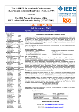
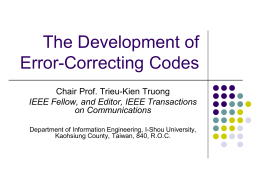
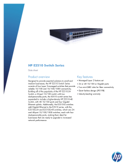
8
DSLAM and Home Network
8.1 Introduction
Chapters 5–7 presented the various versions of xDSL modems (HDSL, ADSL,
G.lite, and VDSL) with their variants. Our approach has essentially been
focused on the description of these modems from an end user’s perspective. This
chapter is divided into two parts dedicated to DSLAM and to home networking,
respectively. A DSLAM may be seen as the complementary of an xDSL end
user’s modem, at the CO side. We have already introduced in Chapter 3 the
concept of DSLAM as the set of xDSL modems installed in the carrier premises.
For each xDSL modem installed at the end user, another xDSL modem is
installed by the carrier between the MDF and the POP of a packet-switching
network carrier (see Figure 3.6). We detailed in Chapter 3 unbundling and the
technical and regulation aspects related to the management of the MDF and of
the DSLAM. We describe in the first part of this chapter the role and interfaces
of a DSLAM. The second part is dedicated to home networking. In reference to
the ITU-T terminology, we have underlined that an ATU-R and an ATU-C
both correspond to a network termination of type 1 (NT-1) and to a line termination (LT). When we have presented the reference points of an ADSL access system (see Figure 6.5), we have introduced the concept of network terminations
of type 2 (NT-2). In the ITU-T terminology, an NT-2 is an optional piece of
equipment that a carrier may provide to the customer to complement his or her
modem (NT-1). The main objective of an NT-2 is to facilitate a fair share
between various pieces of equipment under the responsibility of the end user of
a unique physical access to a data network via the NT-1. In general, an NT-2
consists of the provision of a LAN service also called a home network to the end
user.
227
228
Broadband Local Loops for High-Speed Internet Access
8.2 DSLAM
In a multioperator environment, DSLAMs have an important impact on the
design of the global architecture of multiservice networks. Indeed, a DSLAM is
placed at the boarder between local loops and public networks on which are
connected service providers. These public networks may be of different types,
either circuit-switching–oriented (PSTN managed by an ILEC) or packetswitching–oriented (ATM, IP, Ethernet-based or frame relay networks managed
by a CLEC). A DSLAM is not only a set of xDSL modems used at the end of
each subscriber line. Located either at the EOs or at CO,1 it serves as a protocol
adapter and as a traffic concentrator. We have also underlined in Chapter 3 the
key role of a DSLAM in the unbundling context.
8.2.1
DSLAM Functionalities
A DSLAM is a piece of equipment that assembles multiple xDSL modems. Current DSLAMs available on the market may include up to a few hundreds of
xDSL modem-cards.2 Knowing that an EO concentrates up to 5,000 subscriber
lines, several tens of DSLAMs are in fact installed close to the MDF. By simplification, we assimilate in the following the set of these DSLAMs to a single piece
of equipment. Figure 8.1 illustrates the location of a DSLAM in its typical environment. A DSLAM is a multitechnology piece of equipment, its modem cards
being in general of different types (HDSL, HDSL2, SHDSL, G.dmt, and
G.lite). One distinguishes in Figure 8.1 five types of access lines:
� Case 1: The lines that only transport traditional analog voice channels
do not use any modem or POTS splitter at the DSLAM. Such lines are
directly redirected at the MDF to the inputs of the EO.
� Case 2: The lines used for ADSL and G.lite services transport both ana-
log voice channels and data traffic. Each of these lines needs a modem
and a POTS splitter within the DSLAM. Let us remark that although a
G.lite modem does not need a POTS splitter at the customer premises,
it is not the case at the EO or at the CO.
� Case 3: IDSL lines that are specifically designed for ISDN services and
HDSL lines that are used for T1/E1 leased lines services need a dedicated modem at the DSLAM. On the other hand, no POTS splitter is
required at the CO/EO side. In addition, as ISDN and T1/E1 LL are
1. Chapter 2 explained that the proximity between an EO and its CO depends on the end users’ density.
2. The size of a DSLAM is comparable to the size of an IP router.
Internet
Internet
ATM,
ATM,
Frame
Frame Relay
Relay, ,
Ethernet
Ethernet …
…
Figure 8.1 Location of a DSLAM in its typical environment.
POP #2
Internet
POP #1
IDSL lines and
E1/T1 LL (3)
Sub-E1/T1 LL (4)
EO
IP router
xDSL modem-cards
DSLAM
Traffic
Traffic
concentrator
concentrator
CO
POTS splitter
Web server
MDF
HDSL, HDSL2, SHDSL lines (5)
Subscriber lines
G.dmt and G.lite lines (2)
Traditional POTS lines (1)
DSLAM and Home Network
229
230
Broadband Local Loops for High-Speed Internet Access
fixed bit rate services, they to not need to use a traffic concentrator at
the DSLAM.
� Case 4: HDSL/SHDSL modems may be used to provide circuit-
oriented LL services with a fixed bit rate lower than E1/T1. In that case,
one may use the services of a traffic concentrator in fact quite similar to
an EO in order to concentrate the traffic of various analog lines on
dedicated E1/T1 links.
� Case 5: The HDSL, HDSL2 and SHDSL lines may also transport
packet-oriented data traffic. These packets are forwarded by the
DSLAM toward packet-switching networks.
8.2.2
Reference Model for xDSL Services
In the context of client-server applications like remote access to Web servers, a
DSLAM routes the multiple requests sent by the end users to such or such POP
of an NSP. Figure 8.1 illustrates such a situation for which the NSPs cannot
afford the installation of a POP close to every DSLAM. In other terms, IP networks on which are connected the Web servers are not accessible directly from the
EO/CO but need the crossing of a data network, which is either a long-distance
core network or a MAN. The choice of such or such a POP by the DSLAM is
related to the fact that this POP makes it possible to reach the remote IP network
on which is connected the requested server. The transport network between the
DSLAM and the POPs may rely on various technologies and protocols (ATM,
frame relay, and probably Ethernet in the next few years). This is the reason why a
DSLAM must in general proceed to protocol conversion. Chapter 9 is totally
dedicated to the description of end-to-end protocol architectures. Currently,
ATM or frame relay networks are frequently used between the DSLAMs and the
POPs. Instead of opening as many virtual circuits from the DSLAM to the POPs
as the amount of simultaneous requests received from the end users, a DSLAM
uses a single permanent virtual circuit to be connected to each POP. Thus, in our
example of Figure 8.1, two permanent virtual circuits link the DSLAM to the two
POPs. On the basis of the requested URL, IP packets received from the end users
are forwarded toward such a permanent virtual circuit.
Several technologies are possible to proceed to an upstream traffic concentrator at the DSLAM The choice of technology is a key point in the cost, the
efficiency, and the complexity of the offered services. Current implementations
are in their majority based on ATM switches. Since 2000, DSLAM vendors
consider with an increasing interest the benefits of gigabit Ethernet switches for
concentrating upstream traffic. We have already underlined this evolution from
ATM to Ethernet in the local loop in Chapter 6 when we introduced the concept of EFM. For economy of scale, the modem cards installed within a
DSLAM and Home Network
231
DSLAM are software-programmable. Thus, these cards can be dynamically
reconfigured in order to operate under different modes, including G.dmt,
G.lite, HDSL, HDSL2, and SHDSL. This flexibility assumes that several line
codes and modulation techniques are possible from a same hardware. This is the
reason why an xDSL modem at the CO side is in fact much more complex and
expensive than an xDSL modem at user’s side.
8.2.3
DSLAM Supervision
Because of their multiple functions and of their key role in Internet access provision, efficient tools are necessary to manage the proper working of DSLAMs.
DSLAMs available on the market are equipped with network management tools
like simple network management protocol (SNMP). As an example, such tools are
able to provide statistics on subscriber lines quality in terms of SNR or in terms
of utilization ratio per subcarrier in DMT systems. As mentioned above, a
DSLAM may be under the responsibility of a CLEC. If colocation is possible, it
may be located within the CO or EO building of an ILEC. The IAP installs in
its own room (see Figure 3.8) a work station on which is implemented the
DSLAM management software.
8.2.4
Remote Access Multiplexer (RAM)
Telcordia laboratories (formerly Bellcore) proposed a new version of DSLAM
called RAM, which makes it possible to provide xDSL services to users located
further than 4 km from the EO. Typically, a RAM is a small-size version of a
DSLAM able to manage up to about 10 subscriber lines. A T1/E1 LL is used
between the CO and the RAM. Figure 8.2 illustrates how a RAM may be
attached to a DSLAM in order to serve the most distant users from the CO. The
LTs of these digital LL are directly connected to the internal bus of the DSLAM.
8.3 Home Networking
8.3.1
The Emergence of Home Networking
Typically, the families using more than one PC are those for which the parents
bring back their own laptop at home at the end of the day and where one or several PCs owned by the family are used for private purposes. The homes of these
families are usually connected to the Internet either by means of a cable modem
or of a voiceband or xDSL modem. Let us recall that a modem is called an NT-1
in the ITU-T terminology. An NT-1 is coupled to the telephone line. In their
traditional configuration, these modems enable the connection of a single end
system at a time. The specification of the reference points of an ADSL modem
232
Broadband Local Loops for High-Speed Internet Access
CO
EO
distance < 4 km
DSLAM internal bus
RAM internal bus
To the NSPs
Traffic
concentrator
LT
LT
NT
LT
LT
NT
MDF
T1/E1 LL
RAM
DSLAM
xDSL modem-cards
distance > 4 km
Figure 8.2 Example of RAM in an access network.
outlines the role of and NT-2 (see Figure 6.5). An NT-2 is an optional piece of
equipment that can be provided by the access provider or that can be purchased
by the end user himself or herself in order to have the possibility to connect several end systems on the NT-1. The role of an NT-2 is twofold. First it enables
simultaneous access to public networks via a same NT-1 by multiple PCs. Second, an NT-2 is the equivalent of a LAN connected to the NT-1 via a standardized interface. Whereas a LAN is used for professional purposes, an NT-2 is
used in general for residential purposes. Such a private LAN is called a home network. We have given an example in Chapter 2 of an NT-1 and NT-2 combination in reference to narrowband ISDN access (see Figure 2.11). Two major
functions are dedicated to an NT-1 when it is connected to a home network:
routing and access control. These two functions are carried out by means of an
IP router and of a firewall, respectively.
Knowing that by the end of 2001, about 10 million xDSL lines (essentially
G.dmt and G.lite) were in service in the world, home networking represents a
huge market for electronic chip providers and electronic equipment vendors.
Figure 8.3 (from the ADSL Forum) illustrates the main functions that should be
carried out for home networking. As underlined in Chapter 6, in its current
implementation, ADSL assumes an ATM cell-based transmission format. The
broadband NT-1 (BNT-1) is in charge of the physical layer functions mentioned
in Chapter 6 (modulation, error detection and correction, synchronization).
DSLAM and Home Network
233
Signaling, CAC
TA
Fast
U
data
T
S
TTC-F
C -F
Shaping
Policing
ATU-R
R
SAR
SAR
TTC-I
C -I
SAR
Interleaved
data
B-NT-1
B-NT-2
Figure 8.3 ADSL Forum reference interfaces for home networking.
The BNT-2 is in charge of ATM signaling for the supervision of ATM connections (OAM functions) and of CAC. The decision of acceptance or of rejection
of a new ATM connection is not decided by the BNT-2 but by the nearest
ATM switch in the carriers’ network. The terminal adaptors (TAs) are in charge
of protocol adaptation between the ATM-oriented BNT-1 and the
IP/Ethernet-oriented end-equipment. A TA proceeds to segmentation and reassembly (SAR) of the variable size packets generated by users’ applications. The
function of terminal adaptation is either distributed onto the various end equipment or is carried out after traffic concentration between an NT-2 and a
BNT-1. Several groups of interest are working on a standardization of home
networking: ADSL Forum (TR-011/012 Group), ETSI (TM6 ANA Group),
ATM Forum (Residential Broadband or RBB Group), DAVIC, ITU-T (SG
15/4) and finally IEEE.
Today, many homes are equipped with multiple PCs in North-America,
Europe, and a few countries in Asia. Facing this situation, the most recent versions of cable modems or of xDSL modems include a router and multiple ports
enabling the connection of multiple pieces of end equipment. Depending on
the vendors, the first forms of built-in home networks have appeared on the
market since 2000. In most cases, these first versions of NT-2 enable the connection of a very limited range of end equipment such as PCs, printers, and analog or digital telephone sets to the NT-1.
8.3.2
End Users’ Expectations
These recent years, several polls have been carried out in order to determine consumers’ expectations in terms of home networking [1]. The first demand from
234
Broadband Local Loops for High-Speed Internet Access
the end users is to benefit from real in-home networks that enable them to
spread out the end equipment in the different rooms of the home. Via a single
NT-1 a few pieces or all of this equipment should benefit concurrently from
always-on connections for high-speed access to the Internet. Like a traditional
LAN, the basic role of a home network is to facilitate file and peripheral sharing
within the home. Data applications accessible via PCs such as Web access,
e-mail, and printing represent a global bit rate of a few megabits per second.
Voice applications requirements are low in terms of bandwidth (a few tens of
kilobits per second). Thanks to compression techniques like MPEG-4, video
over PC services are today possible at data rates under 500 Kbps. Traditional
video over TV set requires higher bit rates up to 4 Mbps.
Today, the concept of home networking is enlarged to a great variety of
end equipment and applications. Thus, consumers would like to be able to integrate their digital mobile phone to their home network in order to use it as a
cordless system. The definition of a cordless system is given in Chapter 11. Let
us state precisely that a cordless system assumes the reduced mobility of the end
user. In this way, the cost of a cordless call is much lower than the cost of a regular cellular call. Indeed, operations like end-user localization, handover, or
power control are much easier to achieve in cordless systems than in cellular systems. Consumers also would like to be able to transfer easily information from
equipment such as their personal digital assistants (PDAs), digital cameras, and
digital video recorders (DVRs) onto their home network. They could in this way
share digital documents locally or with distant persons. Playing Internet radio
stations or MP3 files on their home stereo systems is another example or consumers’ demand. At last, a whole range of services deals with the remote control
and telemetry of electrical in-home devices. Such remote controls should make
it possible to regulate the temperature or the lightening within the home (concept of smart home). They could also be used for security purposes by means of
video cameras. Considered one by one, these new services do not represent high
bit rates but some of them (i.e., telephony, video, and conferencing) require
stringent QoS constraints in terms of end-to-end delay and packet loss ratio.
8.3.3
Which Medium for Home Networking?
The previous section listed a wide range of applications based on various pieces
of equipment. This equipment is usually incompatible in terms of networking
because of reliance on different cabling or wireless systems. During the last 5
years, the multiplicity of commercial offers for private devices susceptible to be
connected to a home network has been such that standardization will be necessary in the next years. Schematically, three types of cabling approaches are possible: structured wiring, existing wiring, and wireless systems.
DSLAM and Home Network
235
8.3.3.1 Structured Wiring
Structured wiring assumes the installation of brand new wiring in the home
based, for instance, on UTP copper pairs, coaxial cable, or optical fibers. Economically, a single type of medium is recommended. Today, 10- or 100-Mbps
Ethernet switches or hubs may operate on UTP pairs. Coaxial cable is certainly
too expensive and lacks the mechanical flexibility to be a considered as a futureproof alternative. Finally, optical fibers could be the solution for installations
requiring the highest bit rates. The great default of structured wiring is that it is
in practice applicable only to the case of brand-new apartments or houses, with
recabling an existing house or apartment appearing less realistic.
8.3.3.2 Existing Wiring
The following are examples of existing wiring.
� Home Phoneline Networking Alliance (HomePNA): In the case of exist-
ing buildings or houses, a reuse of the installed wiring seems economically reasonable. Today, three types of wired mediums are installed at
the customer premises. UTP copper pairs traditionally used for analog
telephony are widely deployed in most of the rooms of the house or of
the apartment. A consortium known as the HomePNA has already
published a set of specifications enabling the constitution of home networks from in-home existing copper pairs [2, 3].
Figure 8.4 depicts an example of home network configuration
using the HomePNA standard. An ADSL modem (the BNT-1) is connected to a 10BaseT Ethernet hub or switch. Two PCs (1 and 2)
equipped with an Ethernet card are connected on two ports of this
hub/switch. An analog telephone set is connected to the POTS splitter,
which is itself connected to the existing copper phone wiring. Another
telephone set connected to a PC (PC 2) is used for digital voice (for
instance, a VoIP phone). A HomePNA bridge makes it possible to
extend the range of the home network based on the Ethernet
hub/switch by making it possible to connect PCs directly into the existing phone wiring. Thus, PCs 3 and 4 must be equipped with specific
HomePNA adaptors linking their USB port to a RJ45 phone connector. For such a home network configuration, the NT-2 corresponds to
the set of the equipment included within the dotted line box represented on Figure 8.4. A TA is necessary between the Ethernet
hub/switch and the ATU-R (i.e., the B-NT1) in order to carry out
Ethernet-to-ATM conversion (the set of the NT-2 and TA corresponds
logically to the BNT-2). Multiple IP addresses are dynamically assigned
to the ADSL modem by the ISP, each of these addresses serving a given
236
Broadband Local Loops for High-Speed Internet Access
Analog telephone set
POTS splitter
ATU-R BNT-1
TA
Ethernet hub/switch
New copper wiring
PC #1
Ethernet/Home PNA bridge
NT-2
Phone wiring
PC #3
PC #4
Digital telephone set PC #2
Figure 8.4 An example of a home network based on the HomePNA standard.
piece of end equipment. In our example, up to five IP addresses may be
necessary, one for each of the four PCs and one for the voice-over-IP
phone.
� HomePlug: In-house electrical wiring is another type of medium already
installed at the customer premises. Section 3.8 introduced the HomePlug Powerline Alliance [4], a consortium of vendors interested in the
definition and development of interfaces enabling to use electrical wiring as a home network. The MAC protocol specified in the HomePlug
1.0 reference document is based on OFDM. Compared to HomePNA
networks, home networks based on PLC technology are characterized
by a more limited capacity. According to the state of the technology,
the capacity of such home networks is about 1 Mbps instead of several
megabits per second to share between multiple pieces of end equipment
for HomePNA. Current investigations carried out within the HomePlug Powerline Alliance aim to enable a global capacity on the electrical
home wiring up to 10 Mbps. Let us remark that in general, electrical
wiring is installed in every room; that is not the case for phone wiring.
Electrical wiring is equipped with a larger number of outlets than
phone wiring.
� Coaxial wiring: Many homes are connected to coaxial cable networks all
over the world. Nevertheless, a great disparity exists, especially in
Europe where cable modems are, for instance, widely deployed in
DSLAM and Home Network
237
Belgium but much less popular in France. We mentioned the limitations of coaxial cable in the section dedicated to structured wiring.
8.3.3.3 Wireless Systems
Compared to wired systems, wireless home networks have the advantage of not
needing any recabling at the customer premises. This property will be certainly
an important factor in the competitive context of home networking. Unlike
HomePNA solutions, wireless technologies are better suited to the connection
of mobile or semimobile radio equipment such as GSM cellular phones, laptops,
PDAs or cordless phones to a home network. Numerous vendors proposing different technologies are in competition, each of them expecting their solution to
become the de facto standard by occupying the fastest as possible this market
segment. The IEEE 802.11b and Bluetooth technologies are currently the most
popular approaches for wireless home networking. Other technologies like
home RF, HiperLAN or ultra wideband are also among the candidates for wireless home network. These different techniques are presented in the following
sections.
8.3.4
IEEE 802.11 and IEEE 802.11b
Historically, the first IEEE 802.11 standard, also known as wireless Ethernet,
dates from 1997. This first version operating at 1 or 2 Mbps was replaced by an
enhanced version operating either at 5.5 Mbps or 11 Mbps and known as the
IEEE 802.11b standard in 1999. The two data rates considered for both IEEE
802.11 and IEEE 802.11b correspond to a noisy and to a favorable environment, respectively. Currently, investigations aim to increase the on-line bit rate
up to 20 Mbps for the new IEEE 802.11g standard.
The IEEE 802.11b wireless LAN, also known as wireless fidelity or WiFi,
operates at 2.4 GHz. As it is intended for private usage, no license from the
regulation bodies is necessary to operate a WiFi network. The transmission
power is of 20 dBm for a range of about 50m. Two configuration modes are
possible for WiFi: the infrastructure mode and the ad hoc mode. An ad hoc
IEEE 802.11b network consists of a set of terminal equipment (typically PCs
and printers, for example) able to communicate directly between each other
without any master node or base station. This set of terminals forms an independent basic set service (IBSS). By its nature, the services offered by the ad hoc
mode are limited to best effort asynchronous data transfers. The other configuration mode, called the infrastructure mode, makes it possible to provide specific services to a terminal over a certain area. Infrastructure networks are based
on the usage of base stations called access points (APs). A radio cell defined by an
AP is called a basic set service (BSS). The AP are linked together by means of a
238
Broadband Local Loops for High-Speed Internet Access
traditional Ethernet bus called a distribution system (DS). Figure 8.5 illustrates
an example of IEEE 802.11b network configuration associating three BSSs and
one IBSS. One notices that a terminal may belong to an IBSS and to a BSS
simultaneously. The most popular versions of IEEE 802.11b are based on the
infrastructure mode.
Three different physical layers are possible for an IEEE 802.11 network:
frequency hopping spread spectrum (FHSS), direct sequence spread spectrum
(DSSS), and infrared. FHSS consists of splitting the 75-MHz capacity of a cell
into 75 channels of 1 MHz each. An active terminal (transmitting or listening)
scans permanently these 75 channels according to a procedure that is independent from one cell (IBSS or BSS) to another one. The objective of frequency hopping is to reduce considerably the risk of interference between communication
channels. The main drawback of FHSS is that it reduces considerably the effective capacity of the system due to the switchover time inherent to frequency
hopping. DSSS is better suited to high-speed data transfers than FHSS. The
baseband signal is spread out in the frequency domain in order to reduce the
impact of interference. In each transmitter, information bits are added up with a
binary sequence in the Gallois field. The binary sequence corresponds to a set of
“bits” called chips. The duration of a chip is an integer fraction of a bit duration.
The sequence of chips used in IEEE 802.11 is called a Barker sequence with 11
chips. Figure 8.6 depicts the principle of DSSS. Both IEEE 802.11 and IEEE
802.11b operates with DSSS.
DS
AP #3
AP #1
BSS #1
BSS #3
IBSS
AP #2
BSS #2
Figure 8.5 Example of IEEE 802.11b network.
DSLAM and Home Network
Data (1)
Code word = 11 chips
239
Code word = 11 chips
Barker sequence
Resulting sequence (2)
1 011 01110000100 100 0111
Transmitted data
Amplitude (1)
Frequency
Amplitude (2)
Frequency
Figure 8.6 Principle of DSSS in IEEE 802.11.
A received signal during a bit duration with six chips equal to 0 or 6 chips
equal to 1 corresponds to the bit “1” or “0,” respectively. The Barker sequences
imply a frequency spreading factor equal to 11. DSSS uses 14 channels of 5
MHz each. In IEEE 802.11b, a modulation technique inspired by QPSK called
complementary code keying (CCK) associates to each suite of 8 bits a given phase
according to the value of the first 2 bits and an 8-bit code word according to the
value of the last 6 bits. At the MAC layer, the carrier sense multiple access with collision avoidance (CSMA-CA) protocol has been adopted. The protocol efficiency of this MAC protocol limits the effective capacity of the IEEE 802.11b to
about 6 Mbps. A particular interest has been dedicated to security aspects in
order to prevent a malicious user to access or to listen illegally to the data transferred on the network. For that purpose, the MAC layer includes an encryption
sublayer called wired equivalent privacy (WEP). A detailed description of the
IEEE 802.11b MAC protocol and of CCK is out of the scope of this book. The
interested reader may consult [5, 6].
8.3.5
Bluetooth
Bluetooth is another good candidate for wireless home networking. At the difference of IEEE 802.11b, Bluetooth was conceived initially for applications
requiring low bit rates over a few meters range (between 5m and 10m). Networks with such a very short range qualify as personal area networks (PANs). Like
240
Broadband Local Loops for High-Speed Internet Access
IEEE 802.11b, Bluetooth operates around 2.4 GHz. It uses a bandwidth of 83
MHz in the [2.4 GHz, 2.4835 GHz] band. The transmission power of Bluetooth is on average of a few dBm, much lower than the 20 dBm required by
IEEE 802.11b. Bluetooth technology is based on VLSI electronic chips that can
be placed on any kind of electrical device susceptible to be remote-controlled
(e.g., washing machine, heating system, air conditioning system, home stereo
system, and PDAs) or to communicate with other equipment. Bluetooth is an
ad hoc network. This means that the connection of an equipment to a “piconet”
(a cell with 10m radius) is carried out automatically without any manual configuration. Several piconets may be linked together automatically to form a
“scatternet.” The first piece of equipment to be activated plays automatically the
role of master. The other machines activated in the same cell after the master are
qualified as slaves under the control of this master. Up to seven slaves may
depend on a same master to form a piconet. In other words, an eighth station is
considered automatically as a new master that will control up to seven new slaves
and so on. The masters communicate between each others to form a scatternet.
The FHSS transmission technique is adopted at the physical layer. The 83-MHz
band mentioned above is thus divided into 70 sub-bands; an active piece of end
equipment scanning permanently on these 70 channels. Master stations have the
responsibility to assign randomly the sequence of frequency hops that two
machines have to adopt during their dialogue. About 1,600 frequency hops per
second are thus applied during communications. A detailed description of Bluetooth systems is given in [7]. Today, Bluetooth chips are implemented in such
devices as cellular phones (Ericsson), PC cards (Anycom, 3Com), PDAs (Palm),
and electronic pencils.
8.3.6
Home RF, HiperLAN, and Ultra Wideband
Other wireless techniques are also considered to be possible candidates for wireless home networking. Home RF and HiperLAN operate at 2.4 GHz whereas
ultra wideband operates between 3 and 6 GHz. Meanwhile, the development of
these techniques is less advanced than for the two previous ones. This is the reason why we do not detail their respective announced performance.
8.3.7
Toward a Universal Residential Gateway
8.3.7.1 Residential Gateway
We have listed in Section 3.2 a large variety of possible services that could be
offered on next generation home networks. The most innovative among these
services are those referring to the concept of smart house. We have also underlined that next generation home networks will probably be based for economical
and technical purposes on a hybrid combination of multiple subnetworks using
DSLAM and Home Network
241
various types of mediums. Some of these subnetworks will reuse existing cabling
systems by enlarging their field of utilization (HomePNA, PLC). Figure 8.7
illustrates an example of a home network combining existing phone wiring, Ethernet wiring, and a wireless system. In Figure 8.7, one has represented a residential gateway coupled with a remote modem in charge of interconnecting the
various in-home networks onto a same user’s modem. For downstream traffic, a
residential gateway operates as an IP router to dispatch incoming IP packets to
the right terminal. Locally, the residential gateway must be able to proceed to
protocol conversion in order, for instance, to enable a PDA equipped with a
Bluetooth chip to communicate with a HomePNA PC. In order to facilitate
such local communications without the intervention of a carrier or ISP, the residential gateway must be able to assign dynamically IP addresses to any active
piece of end equipment. Finally, the residential gateway must be able to carry
out synchronous/asynchronous packet multiplexing in order to share the xDSL
link between multiple egress connections. We have also mentioned above the
necessity to protect the private installation from undesirable incoming traffic;
this service is offered by means of a firewall included in the residential gateway.
8.3.7.2 Service Gateway
Because of the multiplicity of the actors (vendors, service providers, carriers)
involved in the market of home networking, the emergence of a standard is necessary. The open services gateway initiative (OSGi) is the most advanced
approach in this matter [8, 9]. The OSGi introduces the concept of a network
Analog
telephone
set
POTS splitter
Modem NT-1
Residential gateway
TA
Ethernet hub/switch
Wireless access point
New copper wiring
NT-2
PC #1
Ethernet/Home PNA bridge
Phone wiring
Digital
telephone set
PC #3
PC #2
Figure 8.7 An example of hybrid home network.
PC #4
242
Broadband Local Loops for High-Speed Internet Access
service gateway that consists of providing each home a unique “virtual service
gateway” based on the OSGi specifications. Thus, one enlarges the concept of
residential gateway to a form of universal residential gateway made of a network
terminal and of a service gateway. The network terminal provides IP bearer services by means of an NT-1 and of an NT-2. The service gateway is an application
server using Java software and located at the customer premises. A piece of terminal equipment may dynamically download from the service gateway service
applications called bundles. If these bundles necessary for the provision of the
required service are not available in the service gateway, the service gateway may
itself download them from dedicated servers located at the CO. In existing networks, the services offered to the end users are fixed and rely on specific terminal
equipment. With OSGi, the idea is then to enable the end users to adapt partially the offered services to their own requirements, independently from the
provider of the basic service.
8.4 Conclusion and Perspectives
The first part of this chapter was dedicated to the description of a DSLAM. We
have seen that in addition to terminating at the EO or CO xDSL links, a
DSLAM serves as a traffic concentrator and as protocol converter. The second
part of this chapter was dedicated to home networking. Ad hoc wireless LANs
may be considered good candidates for the coming home network standard
because they are the most simple to implement. We have seen that IEEE
802.11b and Bluetooth are the most two important competitors for this market
segment. In terms of range and power consumption, Bluetooth seems better
suited to an in-home environment. On the other hand, some estimate that it
should be easy to reduce the power of transmission in IEEE 802.11b in order to
adapt the range to home networking, the reverse being not possible for Bluetooth, which is PAN-oriented. Efforts are currently being carried out to adapt
both systems to the residential environment. Ethernet switches or hubs are
already widely used as an NT-2 coupled to an ADSL modem. In-home networking will probably be based on hybrid technologies. It has been observed
experimentally on real installations that Bluetooth, Home RF, and IEEE
802.11b systems could interfere with microwave systems. Because of the inevitable multiplicity and permanent evolution of the services inherent to the smart
network concept, the definition of a universal residential gateway seems necessary. This is the reason why we have briefly introduced the OSGi standard. An
OSGi that promotes an evolution toward universal home networks should
motivate, for instance, the development of bistandard phones (cellular and
cordless) by the manufacturers.
DSLAM and Home Network
243
References
[1]
Teger, S., and D. J. Waks, “End-User Perspectives on Home Networking,” IEEE Communications Magazine, April 2002, pp. 114–119.
[2]
Bisaglia, P., R. Castle, and S. H. Baynham, “Channel Modeling and System Performance
for HomePNA 2.0,” IEEE Journal on Selected Areas in Communications, Vol. 20, No. 5,
June 2002, pp. 913–922.
[3]
HomePNA, http://www.homepna.org.
[4]
Homeplug Powerline Alliance, http://www.homeplug.org.
[5]
Ala-Laurila, J., et al., “Wireless LAN Access Network Architecture for Mobile Operators,”
IEEE Communications Magazine, November 2001, pp. 82–89.
[6]
Heegard, C., “High-Performance Wireless Ethernet,” IEEE Communications Magazine,
November 2001, pp. 64–73.
[7]
Schneiderman, R., “Bluetooth Slow Dawn,” IEEE Spectrum Magazine, November 2000.
[8]
Marples, D., and P. Kriens, “The Open Services Gateway Initiative: An Introductory
Overview,” IEEE Communications Magazine, December 2001, pp. 110–114.
[9]
OSGi, http://www.osgi.org.
Selected Bibliography
Horowitz, B., N. Magnusson, and N. Klack, “Telia’s Service Delivery Solution for the
Home,” IEEE Communications Magazine, April 2002, pp. 120–125.
Muñoz, L., et al., “Optimizing Internet Flows over IEEE 802.11b Wireless LANs: A
Performance-Enhancing Proxy Based on Forward Error Correction,” IEEE Communications Magazine, December 2001, pp. 60–67.
Paradyne Corporation, The DSL Source Book: Plain Answers About Digital Subscriber Line
Opportunities, 1997.
Valtchev, D., and I. Frankov, “Service Gateway Architecture for a Smart Home,” IEEE
Communications Magazine, April 2002, pp. 126–132.
Baixar