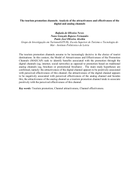
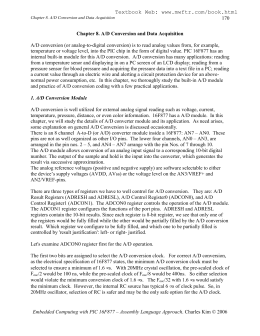
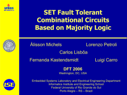
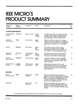
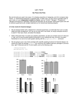
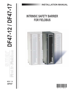
FICHA TÉCNICA DE PRODUTO
PRODUCT DATASHEET
HMI – Automação e Instrumentação, Lda.
Rua Dr. Oliveira Salazar, nº 88
4780-453 Santo Tirso
PORTUGAL
Web: www.hmi.pt
Tel. +351 252 809 124
Fax. +351 252 859 298
Email: [email protected]
Data Sheet DS/695FI-EN Rev. H
Model 695FI
Field Indicator
Digital LCD or analog meter
– allows to select the proper indication
Programmable meter and HART configurator
– combines signal display with password protected
configuration capabilities for transmitter management
Rugged, compact, lightweight, enclosure to IP67
– enables installation in industrial environments
Compatible with all 4-20 mA, 2-wire systems
Square root signal characterization
– allows measurements linearization
Comprehensive certification approvals
– give high applicability in plant hazardous areas
600T EN Series Transmitters
Model 695FI
Model 695FI field indicator provides simple and low cost er mote
indication of a pr ocess variable on an easy to r ead meter ,
ensuring the most useful display for any specific application.
Traditional analog indicator is available with standar d 0-100%
linear or 0-10 squar e root graduations or special scales to be
specified.
In addition to parallel transmitter wiring the terminal block 695FI
provides series wiring through junction box connection facility.
Alternatively to the pr evious options, model 69 5FI, of fers a
programmable signal meter which integrates LCD plus bargraph
indications (ProMeter). This kind of display is also available with
HART configuration capabilities (CoMeter).
Both these meters feature:
one 5-digit numeric indication (top)
one 10-segment bargraph indication (central)
one 7-digit alphanumeric indication (bottom)
a membrane keypad with 4 tactile feedback keys
DS/695FI-EN Rev. H
The functionality as METER is achieved by the 10-segment
bargraph which gives an analog 0-100% indication and by the 5digit display which gives a digital indication programmable from
the following options:
• 4 to 20 mA
• 0 to 100%
• engineering unit
Programmability is carried out using the four keys, allowing to
define linear or square root indication for mA or engineering unit;
for this latter, also indication range (zer o and full scale values)
can be chosen related to the unit which is defined in HART table;
these parameters can be automatically uploaded fr
om the
transmitter where 695FI with CoMeter is remotely connected.
As CONFIGURATOR , the device keypad of CoMeter only
allows easy management of the associated transmitter; the 7digit alphanumeric display provides comprehensive feedback via
menù driven operations. This configuration device operates in
compliance to standar d definition of universal and common
practice HART commands as explained in the following list:
PV reading
Analog output and % output reading
Secondary variables reading
Transmitter tag reading
Sensor number reading
Up/Down scale setting reading
Upper and Lower Range limit reading
Change output transfer function (square root)
Change units
Change range (ranging)
Change damping
Transmitter number (assembly reference)
Reranging (wet calibration)
Loop test
Output trimming (directly using CoMeter or by external DVM)
Zero alignment (sensor trim)
Overall passwor d pr otection ensur es operational security ,
avoiding unauthorized access to any CoMeter operation.
A CoMeter remotely installed from transmitter allows convenient capability of configuration at easy accessible site.
•
•
2
• Password
• Configuration
• Trimming
• Damping
• Square root
• etc
600T EN Series Transmitters
Model 695FI
DS/695FI-EN Rev. H
Functional specification
Environmental limits
Input range
Relative humidity
4 to 20mA nominal
Operating range
3.6 to 22mA (for CoMeter ensuring HART functionality)
Maximum overload (for 2 minutes)
Analog indicator : 150% of input range
CoMeter and ProMeter: 110mA (23mA indication).
A current less than 3.4mA will blank the display
Voltage drop
analog indicator : 0.2Vdc
ProMeter : 2Vdc
CoMeter:
– less than 2.6Vdc @ full scale and 20°C
– 2.8Vdc @ max temperature (including HART modulation)
Meter/indication range
CoMeter and Prometer LCD :
5-digit (±99999 counts) programmable with 7.6mm. high (3in),
7-segment numeric characters plus sign and digital point for digital
indication of output value in percentage, current or engineer unit;
10-segment bargraph display (10% per segment) for analog
indication of output in percentage;
7-digit with 6mm. high (2.3in), 14-segment alphanumeric
characters, for engineer units and configuration display
Analog : 36mm (1.4in) scale on 90°; available scales are
0-100% linear, 0-10 square root or special on request.
Update time
Analog indicators : 0.5sec
CoMeter and ProMeter: 0.7sec
Operative limits
Temperature limits
Ambient (is the operating limit)
analog indicator: –40 to +85°C (–40 to +185°F)
CoMeter and ProMeter : –20 to +70°C (–4 to +158°F)
Lower limit can be down to –40°C (–40°F) keeping loop integrity and
without meter damage (the display will be blank)
Storage
– 40 to +85°C (–40 to +185°F)
Reference: 60% ±25%
Operative, transportation and storage limits : 0 and 100%
condensing permissible
EMI/RFI (SAMA PMC 33.1)
Operative limits : Class 3 abc, field strengths up to 30V/m
(Frequency range: 20 to 1000MHz)
Wet and dust-laden atmospheres
The field indicator is dust and sand tight and protected against
immersion effect as defined by IEC 529 to IP 67 or by NEMA 4X.
Hazardous atmospheres
– INTRINSIC SAFETY/ EUROPE
ATEX/CESI approval
EC-Type Examination Certificate no. CESI 01ATEX015
Category 1 equipment for Zone 0 (Gas) and Zone 20 (Dust)
For Category 1 Stainless Steel enclosure only
ATEX II 1 G Ex ia IIC T6 T5 Ga (–40°C ≤ Ta ≤ +40°C)
ATEX II 1 G Ex ia IIC T4 Ga (–40°C ≤ Ta ≤ +85°C)
ATEX II 1 D Ex ia IIIC T50°C Da (–40°C ≤ Ta ≤ +40°C)
ATEX II 1 D Ex ia IIIC T95°C Da (–40°C ≤ Ta ≤ +85°C)
Category 2 equipment for Zone 1 (Gas) and Zone 21 (Dust)
For Category 2 Aluminiun or alternatively Stainless Steel enclosure
ATEX II 2 G Ex ia IIC T6 T5 Gb (–40°C ≤ Ta ≤ +40°C)
ATEX II 2 G Ex ia IIC T4 Gb (–40°C ≤ Ta ≤ +85°C)
ATEX II 2 D Ex ia IIIC T50°C Db (–40°C ≤ Ta ≤ +40°C)
ATEX II 2 D Ex ia IIIC T95°C Db (–40°C ≤ Ta ≤ +85°C)
– FLAMEPROOF/EUROPE
ATEX/CESI approval
EC-Type Examination Certificate no. CESI 01ATEX011
ATEX II 2 G Ex d IIC T6 (–40°C ≤ Ta ≤ +70°C)
ATEX II 2 G Ex d IIC T5 (–40°C ≤ Ta ≤ +85°C)
ATEX II 2 D Ex d tD A21 IP67 T80°C (–40°C ≤ Ta ≤ +70°C)
ATEX II 2 D Ex d tD A21 IP67 T95°C (–40°C ≤ Ta ≤ +85°C)
– TYPE "N"/EUROPE
ATEX CESI type examination
Design compliance by Certificate no. CESI 02 ATEX074
II 3 GD T50°C, EEx nL IIC T6 (–40°C ≤Ta ≤+40°C)
T95°C, EEx nL IIC T4 (–40°C ≤Ta ≤+85°C)
– CANADIAN STANDARDS ASSOCIATION and
FACTORY MUTUAL:
Explosionproof: Class I, Div. 1, Group B, C, D
Dust ignitionproof: Class II, Div. 1, Group E, F, G
Suitable for: Class II, Div. 2, Group F,G; Class III, Div 1,2
Nonincendive: Class I, Div. 2, Group A,B,C,D
Intrinsically safe: Class I, II, III, Div. 1, Group A,B,C,D,E,F,G
– GOST (Russia), GOST (Kazakistan),
based on ATEX
Operative limits
Temperature limits
Ambient (is the operating limit)
analog indicator: –40 to +85°C (–40 to +185°F)
CoMeter and ProMeter : –20 to +70°C (–4 to +158°F)
Lower limit can be down to –40°C (–40°F) keeping loop integrity and
without meter damage (the display will be blank)
Storage
– 40 to +85°C (–40 to +185°F)
3
600T EN Series Transmitters
Model 695FI
Performance specification
Stated at ambient temperature of 23°C ± 3K (75°F ± 5), relative
humidity of 50% ± 20% and atmospheric pressure
Indication accuracy
analog indicator : ± 2% fsd
CoMeter and ProMeter
– digital : ± 0.10% of max span(16 mA) ± 1 digit
– analog (bargraph) : 10%
Resolution for CoMeter and ProMeter
DS/695FI-EN Rev. H
Electrical connections
Two 1/2 NPT or M20x1.5 or PG 13.5 or 1/2 GK threaded conduit
entries, direct on housing.
Terminal block
Three screw terminals suitable for wirings up to 2.5mm2 (14AWG)
and three connection points for test and communication purposes.
Grounding
Internal and external 6mm2 (10AWG) ground termination points are
provided.
± 0.025% (12-bit conversion)
Mounting
Ambient temperature
Total effect per 1K (1.8°F) change between the limits of
–20 and +80°C (–4 and +176 °F).
CoMeter and ProMeter: ± 0.15% of max span (16 mA)
EMI/RFI
Total effect : ± 0.10% from 20 to 1000MHz and for field strengths
up to 10V/m when instrument is properly installed.
Physical specification
Materials
Housing and covers
Aluminium alloy with light gray (RAL 9002) baked epoxy finish;
AISI 316 L ss.
Covers O-ring
Buna N
Identification tag
AISI 316 ss permanently mounted.
40 characters max on three lines (legend to be specified).
Mounting bracket (*)
Plated carbon steel with chrome passivation;
AISI 316 L ss
(*) U-bolt material: AISI 400 ss.
4
Vertical position on a 60mm or 2in pipe by bracket.
Net weight
0.9kg. approx (2lb) (without mounting bracket).
Packing
Expanded polythene box.
600T EN Series Transmitters
Model 695FI
DS/695FI-EN Rev. H
MOUNTING DIMENSIONS (not for construction unless certified) - dimensions in mm (in)
Meter housing
Electrical connection
100 (3.93)
Locking fastener
for cover (EEx d only)
128 (5.03)
100%
GARD
ER
KE L
mA
!
E
T QU
AN
E'T H E N
W
12.000 *
0% / - - - - - /
15 (0.59)
Certification
tag
N
IO
NS
L ES
C
CI R I R
C
U
SONT SO
I TS AL I V US T
E
E
CU TS
I
95 (3.74)
Terminals
side
55 (2.17)
50 (1.97)
170 (6.69)
90 (3.54)
5
ERCLE BIEN F
UV
E
CO VER TI GH RM
E P CO
T
E
600T EN Series Transmitters
Model 695FI
DS/695FI-EN Rev. H
WIRING DIAGRAM
695FI as indicator only
2600T transmitter terminal
M
Internal
ground
M
TEST
To receiver/
power supply
TEST
COMM
COMM
M
WIRING DIAGRAM AVAILABLE ONLY WITH ANALOG OUTPUT METER
External
ground
2600T transmitter terminal
M
695FI as junction box
M
TEST
COMM
To receiver/
power supply
TEST
WIRING DIAGRAM FOR ALL METER VARIANTS
6
COMM
600T EN Series Transmitters
Model 695FI
DS/695FI-EN Rev. H
ORDERING INFORMATION model 695FI Field Indicator
Select one character or set of characters from each category and specify complete catalog number.
BASE MODEL – 1st t o 5th ch aract ers
6
9
5
F
I
XXXXX
X
X
X
X
X
F ield In dicat or
6th t o 10th ch aract ers
U se code
00000
Mounting bracket – 11th ch aract er
C arbon st eel (n ot su it able wit h A IS I h ou sin g)
A I S I 3 1 6 ss
2
3
Electrical certification – 12th ch aract er
Gen eral pu rpose
A TEX Grou p II C at egory 2 GD - F lameproof Ex d II C T6, T5
A TEX Grou p II C at egory 1 GD - In t rin sic S afet y Ex ia II C T6, T5, T4
A TEX Grou p II C at egory 2 GD - In t rin sic S afet y Ex ia II C T6, T5, T4
A TEX Grou p II C at egory 3 GD - Ty pe of prot ect ion " N " Ex n L design complian ce
F act ory Mu t u al (F M) an d C an adian S t an dard A ssociat ion (C S A ) approv als
GOS T (Ru ssia) EEx ia
GOS T (Ru ssia) EEx d
GOS T (Kaz akist an ) EEx ia
GOS T (Kaz akist an ) EEx d
Housing material and electrical connection – 13th ch aract er
A lu min iu m alloy
A lu min iu m alloy
A lu min iu m alloy
A lu min iu m alloy
A I S I 3 1 6 L ss
A I S I 3 1 6 L ss
A I S I 3 1 6 L ss
A I S I 3 1 6 L ss
Output meter - 14th ch aract er
1/2in N P T
M20 x 1.5 (C M20)
P g 13.5
1/2in GK
1/2in N P T
M20 x 1.5 (C M20)
P g 13.5
1/2in GK
P roMet er, S t an dard calibrat ion
P roMet er, S pecial calibrat ion
A n alog ou t pu t in dicat or lin ear 0– 100% scale
A n alog ou t pu t in dicat or squ are root 0– 10 scale
A n alog ou t pu t in dicat or, special gradu at ion (t o be specified for lin ear scale)
A n alog ou t pu t in dicat or, special gradu at ion (t o be specified for squ are root scale)
P rogrammable sign al met er an d H A RT con figu rat or (C oMet er)
P rogrammable sign al met er an d H A RT con figu rat or (C oMet er – cu st omer con figu rat ion )
1
F
L
M
N
8
R
U
K
A
(N o t e 3 )
(N o t e 3 )
(N ot es 1, 3)
(N ot es 1, 3)
(N o t e 2 )
(N o t e 2 )
(N ot es 1, 2)
(N ot es 1, 2)
1
2
3
4
A
C
D
F
3
5
7
8
9
Z
P
W
Labels language - 15th ch aract ers
En glish
German
E
G
Note 1:
Not available with Electrical certification code 8
Note 2:
Not available with Carbon steel bracket code 2
Note 3:
Not available with Electrical certification code L
7
Our offering:
Actuators and
Positioners
Device Management,
Fieldbus and Wireless
Force Measurement
Natural Gas
Measurement
Analytical Instruments
Flow Measurement
Level Measurement
Pressure Measurement
Recorders and
Temperature
Controllers
Measurement
HMI – Automação e Instrumentação, Lda.
Rua Dr. Oliveira Salazar, nº 88
4780-453 Santo Tirso
PORTUGAL
Web: www.hmi.pt
Tel. +351 252 809 124
Fax. +351 252 859 298
Email: [email protected]
ABB Ltd.
Process Automation
Howard Road
St. Neots
Cambridgeshire PE19 8EU
UK
Tel: +44 (0)1480 475321
Fax:+44 (0)1480 217948
ABB Inc.
Process Automation
125 E. County Line Road
Warminster
PA 18974
USA
Tel: +1 215 674 6000
Fax:+1 215 674 7183
ABB Automation Products GmbH
Process Automation
Schillerstr. 72
32425 Minden
Germany
Tel: +49 551 905 534
Fax:+49 551 905 555
ABB S.p.A.
Process Automation
Via Statale 113
22016 Lenno (CO)
Italy
Tel: +39 0344 58111
Fax:+39 0344 56278
www.abb.com
Note
We reserve the right to make technical changes or
modify the contents of this document without prior
notice. With regard to purchase orders, the agreed
particulars shall prevail. ABB does not accept any
responsibility whatsoever for potential errors or
possible lack of information in this document.
We reserve all rights in this document and in the
subject matter and illustrations contained therein.
Any reproduction, disclosure to third parties or
utilization of its contents - in whole or in parts – is
forbidden without prior written consent of ABB.
Copyright© 2013 ABB
All rights reserved
Sales
Service
DS/695FI-EN Rev. H 02.2013
Contact us
Baixar