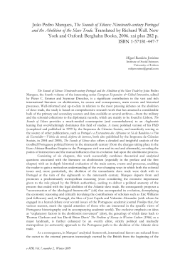
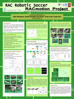
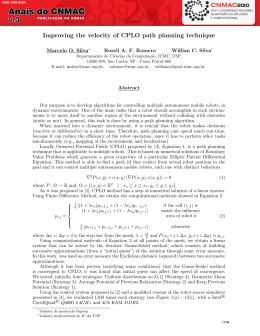
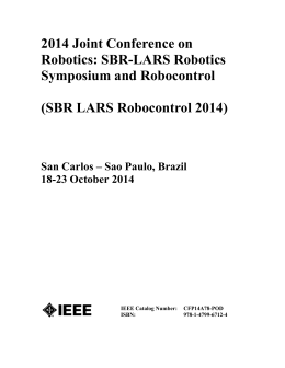
ABCM Symposium Series in Mechatronics - Vol. 3 - pp.246-255
c 2008 by ABCM
Copyright °
MASTER-SLAVE SERVO-BILATERAL CONTROL OF DIRECT DRIVE
ELECTRICAL MANIPULATORS
Bruno Favoreto Fernandes Soares, [email protected]
Filipe Sacchi da Silva, [email protected]
Ilana Nigri, [email protected]
Camilla Bacellar Mello, [email protected]
Marco Antonio Meggiolaro, [email protected]
Pontifical Catholic University of Rio de Janeiro, Rua Marquês de São Vicente 225 Gávea, Rio de Janeiro, RJ, Brazil
Abstract. Telerobotics is an important area with several practical applications such as in toxic and nuclear material
manipulation, telesurgery, civil engineering, law enforcement and aerospace and subsea environments. These systems
are based on a master-slave architecture, where the operator directly interacts with a master manipulator, whose
sensors are used to define reference positions and trajectories for the slave robot. To increase the remote manipulation
efficiency, it is highly desirable that the teleoperator feels the same forces to which the slave robot is subjected, either
scaled – e.g. scaled down in civil engineering or scaled up in microsurgery – or not. With this improved haptics, most
tasks can usually be completed in a shorter time and with better results. In this work, two electrical manipulators are
designed and built to implement a master-slave architecture. Both low power master and high power slave robots have
two degrees of freedom each, computer-controlled using A/D and D/A boards. Servo-bilateral control is implemented
in the developed software, in which the errors between both robots are measured to calculate the slave control forces
and the master force feedback. This particular implementation does not need the use of force sensors, decreasing the
system’s final cost. Experiments show that the slave robot, powered by two DC motors with peak 4.5hp each, is able to
achieve high average speeds of the order of 8.5rad/s in its joints, with rise time as low as 0.15s for a 90 degree step.
The implemented servo-bilateral control is able to provide stable force feedback to the master robot, with a delay of
only 0.1s between the two manipulators.
Keywords: telerobotics, master-slave manipulators, force feedback, haptics, servo-bilateral control
1. INTRODUCTION
Telerobotics has always been an important research topic since the beginnings of industrial robotics in the 1950’s.
Tasks in hard to reach and hazardous environments have been inspiring scientists to develop remote controlled systems,
making several procedures safer, more repeatable and cost effective. Teleoperation allowed for a huge progress in
previously dangerous tasks, assisting human labor at industries and providing technological innovations in new areas. A
few of the applications of teleoperation include telesurgery over the internet, radioactive materials handling, underwater
tasks at high depths, space missions, rescue operations in unsafe areas, and work in sterilized environments (which can
degrade the immunological system of workers).
Teleoperation is the field in robotics that deals with remote system control through a communication link. A
teleoperated system consists basically of two main devices: the Master and the Slave stations. Both
stations/manipulators can be distinguished primarily by their function. The Master Station is usually designed to be
lightweight and ergonomic, manually operated to send signals to the Slave Station, which effectively performs the task
replicating the master’s movements. The master manipulator can be a scaled version of the slave system, but this is not
necessary if the direct and inverse kinematic models of both systems are known. It is necessary for the operator to have
feedback of the slave’s movements, which is usually accomplished through visual feedback using cameras. This
architecture is traditionally used to perform a wide range of tasks, such as those that take place on constant changing
environments.
Implementing telerobotics can result in several benefits regarding overall precision, repeatability and task variety in
comparison to human performed tasks. Furthermore, enhancements in safety and operator’s integrity also become clear,
especially in industry fields where unhealthy environments are common. On the other hand, operating remote
equipment creates certain difficulties such as the dissociation between operator and the actual task being accomplished
and interaction problems with the end effectors. Therefore, methods to improve the interaction between operator and
manipulator should be used to reduce the impact of these difficulties on the system’s performance.
In critical tasks, it is necessary to have a reliable communication link between the systems - the connection must not
be lost during a procedure. Such link must be fast because excessive delays can compromise the task. In tasks where
significant delays are unavoidable due to long distances between master and slave, such as in space or planetary
teleoperation, where the delays are essentially constant, it is desirable to generate renderings of an estimator output.
This estimator must consider a known constant communication delay to generate computer renderings of the predicted
slave state when the current master commands are actually applied to the slave. This estimator is constantly updated
with the slave’s sensor readings to correct for cumulative prediction errors, which can be accomplished with, e.g., a
Kalman filter.
Another way to improve the teleoperation performance is to make the operator feel the actual forces experienced by
the slave. Such haptic feedback is very desirable, in special for delicate tasks such as telesurgery (Friconneuau et al.,
2002). The operator is expected to feel an opposing force to the desired movement, generated by the master robot to
replicate the actual forces felt by the slave system. To implement this, the master system must have not only position
sensors such as encoders, but also motors to actuate each joint and generate the force feedback.
The forces felt by the slave system can either be directly measured using force sensors (Fig. 1) or they can be
inferred from other sensor data such as the position errors obtained from the difference between the slave and master
encoder readings.
Figure 1. Teleoperated system schematics
The former method, using force sensors, is able to better reproduce the actual forces sensed by the slave system. The
force sensors are used at the slave manipulator to close the control loop at each joint by creating torques at the master’s
motors. This method works by reproducing the forces sensed by the slave, often scaled up or down. However, such
control can become unstable for stiff environments or when high force feedback gains are used. In addition, the use of
force sensors significantly increases the cost of the teleoperation system.
The latter method, with force feedback inferred from the joint position readings, is an inherently stable and
inexpensive control methodology. The best example of such methodology is the Servo-Bilateral Control (Miyazaki et
al., 1986), which will be addressed in the next section.
In this work, one master and two slave electric manipulators are built and controlled using a PC computer. The
manipulators, with two degrees of freedom each, are controlled using PID. One of the slave systems developed is a high
power (up to 9HP) direct drive manipulator, which is able to perform high speed tasks. Servo-Bilateral Control is
implemented to perform teleoperation tasks with force feedback. Experiments show the effectiveness of the developed
system.
2. ANALYTICAL BACKGROUND
2.1. PID Control
According to Craig (2003) and Ogata (2003), the Proportional-Integral-Derivative Control (PID) is one of the most
common techniques because of its ease of implementation and calibration. This happens because PID control does not
require a prior knowledge of the system dynamic effects. This technique can be described as a mono-variable control
with the difference between the measured and desired positions of each link (so called errors) as input variables and an
output value that somehow acts upon this error. In this teleoperation study, the input variable is the angular error
between the joints of the master and slave manipulators, and the output variable is the voltage applied at the motors’
terminals in order to reduce this error.
The PID Control can be split into three distinct terms that gave this technique its name. The proportional term is a
model of a linear spring whose extension is given by the position error. Thus, the objective of this term is to reduce the
difference between the master and slave joint angles. The derivative term can be described as a damper, therefore being
dependent on the error rate, or the difference between the master and slave joint velocities. Finally, the integral term is
responsible for reducing the residual steady-state error, mainly related to friction, gravity or other disturbances on the
controlled system. The integral term, however, doesn’t have a physical equivalent, but it can be mathematically defined
as a factor that is proportional to the time integral of the measured errors.
Because of the large variety of the possible systems to be controlled and their own characteristics and responses, it is
necessary to study the influence of each of these factors onto each system individually. For each manipulator joint i,
three gains are used, one for each of the PID terms: KPi, KIi, KDi.
Considering qdes,i and qi as the desired and measured positions of joint i, qdes ,i and qi as the desired and measured
velocities of joint i, and τPi, τIi and τDi as the resulting control torques, the three parts of the PID control are:
t
τ Pi = K Pi ⋅ ( qdes ,i − qi ), τ I i = K I i ⋅ ∫ ( qdes ,i − qi )dt, τ D i = K D i ⋅ ( qdes ,i − qi )
(1)
0
In the implementation of teleoperation, the desired values are taken from the joint sensor readings of the master
manipulator, the measured values are the ones from the slave, and the torques are then applied to the slave system.
The complete PID control formula for each joint is obtained by adding the three terms above, resulting in the control
torque to be applied to the slave’s joint i:
t
τi = K Pi ⋅ ( qdes ,i − qi ) + K Di ⋅ ( qdes ,i − qi ) + K Ii ⋅ ∫ ( qdes ,i − qi )dt
(2)
0
If direct current (DC) electrical motors are considered, then the control torque is approximately proportional to the
applied electric current. Therefore, current control systems would be desirable at each motor, in special if non-linear
control techniques are used, such as Computed Torque Control (Spong and Vidyasagar, 1989).
However, if a current control loop is not available, speed controllers can also be used. Speed controllers are easier to
find than current control systems, and the high power versions have a significantly lower cost than current control
equivalents. The speed controller is a feedback system to adjust the DC motor voltage, using single loop (speed loop) or
cascaded loops (speed and current loops). Thus, the speed controller electronics is not necessarily pure voltage control
for a DC motor. However, assuming the applied currents are well under the saturation of the electronic system, the
voltage applied by the speed controller is then proportional to the control output, and sometimes the proportionality
factor is embedded into the values of KPi, KIi and KDi, which are directly calibrated to convert position errors into
control voltage. Although the calibration of a PID structure is resumed to fit only three parameters, there are several
methods to tune a PID controller and many configurations of PID structures.
The design of a PID controller can be a challenging task. The PID gain tuning is even more difficult in robotic
manipulators, due to dynamic coupling among the links. In this work, the PID gains are tuned assuming no coupling
among the joints, i.e., independent PID control.
For such decoupled systems, there are several references in the literature about calculation methods for the PID
gains based on the system response to a step input and the associated settling time (O’Dwyer, 2006; Yu, 2005). Other
methods are found in Astrom and Hagglund, 1995; St. Clair, 1990). In this work, the manipulator gains are calibrated
first based on the system rise time (to obtain the proportional gain), then on critical damping (to avoid oscillations, thus
obtaining derivative term), and finally on the steady-state error (for the integral gain). The calibration is independently
performed for each link of the manipulators, therefore it does not consider the dynamic coupling behavior between
them.
2.2. Servo Bilateral Control
A very common force feedback technique uses the errors between the master and slave positions not only to apply
control torques to the slave, but also to close the control loop joint-wise applying torques back to the master system.
This method, referred to as Servo-Bilateral Control (Miyazaki et al., 1986), can be easily implemented because it does
not require additional components since it only needs the same sensors already used by the PID control. This fact
contributes to lower the overall costs. The only requirement is that the master manipulator must have active joints, with
motors able to apply appropriate forces back to the operator.
The servo-bilateral control is based on the difference between the positions of each master and slave joint (position
error) to calculate the torques at both manipulators, using a linear control such as PID. At the slave robot, the torques
will bring its links to the desired position (the master’s position), using e.g. PID control gains defined in the transfer
function Gs, see Fig. 2. The master will implement force feedback through another transfer function Gm, which will
calculate the torques to be applied back to the operator. If Gm is equal to Gs, then the technique is called Symmetrical
Servo-Bilateral Control. For tasks involving heavy loads, such as in civil engineering, the master gains are significantly
smaller than the slave ones, resulting in force amplification from the operator. On the other hand, in delicate tasks such
as neurosurgery, usually the slave gains are much higher in order to convert large operator movements and forces into
small delicate ones at the performed task. Figure 2 shows the block diagram of Servo-Bilateral Control for a one-degree
of freedom system with generalized coordinate θ (θm for the master and θs for the slave). Note that the angular error ∆θ
is used to obtain both master and slave torques τm and τs.
Figure 2. Servo-Bilateral control schematic for a single degree of freedom system
It is also worth mentioning that the described approach is easily implemented when the master robot is a scaled
version of the slave and all joints are rotary, because the angular positions of each joint are directly correlated. If this
were not the case, then the direct and inverse kinematic equations of each of the robots would need to be used to
correlate end-effector errors, instead of joint errors, and to generate appropriate torques at each joint that would result in
similar or scaled end-effector wrenches.
3. EXPERIMENTAL SYSTEM
3.1. Manipulator Design
In this work, three electrical robot manipulators are developed, with 2 degrees of freedom each. The manipulators
are developed according to the SCARA configuration (Selective Compliance Arm for Robotic Assembly), which
assumes that the first and second joint axes are parallel. Here, to decrease the system inertia, both motors of each of the
manipulators are attached to the fixed base, while the second link is driven through a timing belt. The architecture of
each of the systems is shown in Fig. 3. In the present work, the robots’ movements are restricted to a horizontal plane,
thus eliminating any gravity effect on the system.
Figure 3. Two-degree of freedom manipulator using timing belts
Each manipulator has two direct current motors (one for each link), transmission system, encoders and tachometers.
The three manipulators are designed using the CAD software SolidworksTM, which makes it possible to optimize the
components’ positions and preview the final dimensions, see Fig. 4. Since the master manipulator would serve as a
“joystick” to a human operator while the slaves would reproduce its movements, the master is developed with reduced
scale and power to improve the ergonomic aspect and to avoid injuring the operator.
encoder
SLAVE
tachometer
coupler
MASTER
joint 1
DC
motor
encoder
tachometer
joint 1
DC
motor
link 1
joint 2
link 2
endeffector
belt
joint 2
DC
motor
link 2
endeffector
tachometer
encoder
tachometer
encoder
Figure 4. Simplified CAD models of the master (left) and slave (right) manipulators
The structural components of the three manipulators are built using aluminum alloys due to their high stiffness-todensity ratio, reducing dynamic effects without adding link flexibility that could compromise the system’s accuracy.
The links are built using medium strength alloy 6061-T6, while the robot base structure uses a lower strength (and
lower cost) alloy 5052.
Three different DC motors are used to drive the manipulators. The master system uses low-power DC gearmotors
Büehler 1.61.046.311, weighing 150g each, with gear ratio 2.9:1. The motor nominal voltage is 12V, however it is
operated overvolted at up to 24V without significant overheating.
The first slave system developed uses 24V 0.5HP DC surplus gearmotors, model VDO Anteriebstechnik GmbH. To
improve the slave response, a second slave system is developed with high power motors Magmotor S28-400, weighing
3.13kg, with maximum mechanical power output of 4.5HP each. The high power and torque of such motors allow for
the use of direct drive, i.e., no gears or speed reductions are necessary. This leads to a high speed system with virtually
no backlash.
Small DC motors attached to high resolution encoders, with 2048 pulses per revolution, are coupled to each of the
actuator motors. They work passively as DC generators to measure both joint position, from the attached encoders, and
speed, from the generated output voltage. It’s important to emphasize that the coupling between the active and passive
DC motors must be very rigid and without any slippage, otherwise this would result in large position errors. Backlash
from the joint shaft keys and keyways must also be avoided, which is accomplished using oversized key stock for an
interference fit between joint shafts and robot links. Also, the timing belts need to be reasonably tensioned to avoid
backlash and compliance issues. A belt tensioner is implemented using small roller bearings attached to the links. More
details of the developed robots can be found in (Favoreto, 2006; Mello, 2006; Nigri and Meggiolaro, 2005; Sacchi,
2006). Figure 5 shows the fully assembled master manipulator and the high power slave robot.
SLAVE
encoder
MASTER
tachometer
encoder
coupler
tachometer
coupler
Magmotor
Büehler
motor
link 1
joint 2
joint 2
link 1
link 2
link 2
Figure 5. Master manipulator (left) and high power slave manipulator (right)
The master system above has link 1 length (distance between the timing pulley centers) equal to 173mm, and link 2
length 163mm (measured between joint 2 and the end-effector), all made out of 1” × ½” solid aluminum bars. Both
pulleys have 20 teeth and primitive diameter 12.3mm, using a 1520 MXL timing belt between them. Joint 2 uses a 5mm
diameter steel shaft with ball bearings.
The high power slave system has link 1 length 244mm with 2” × 1” cross section, and link 2 length 230mm with
1½” × 1” section. Both pulleys have 28 teeth and primitive diameter 44.6mm, using a 248 XL timing belt. Joint 2 uses a
keyed ½” diameter steel shaft with ball bearings and shaft collars. Shaft couplers connect the active DC motors to the
tachometer/encoder systems. Note that both manipulators have similar geometries, one being a 1.41:1 scaled version of
the other.
3.2. Computer-Manipulator Interface
To implement the control system, an interface responsible for reading the encoder and tachometer signals and
generating the output voltages to the manipulators is necessary. In long distance teleoperation, each master and slave
robot needs a dedicated computer to perform its control loop, in addition to a communication line between them. On the
other hand, several teleoperation tasks can be performed with master and slave systems sharing the same computer
system, thus avoiding communication delays. This can be done whenever the master and slave are at short distances
from each other. This is the approach adopted in this work, which is aimed to study the force feedback behavior and not
the effect of significant time delays due to the communication line.
The control system is implemented on a PC computer using a ServoToGoTM board, which has 8 A/D inputs, 8
encoder inputs and 8 D/A outputs. No additional signal conditioner hardware is necessary since all sensors are already
compliant with the board specifications. However, the low power output of the D/A board requires the use of a power
amplifier to deliver higher voltage and current to the manipulators. RoboteQTM amplifiers/controllers are used to
interface the computer with each of the manipulators. They are able to read D/A output signals - low power 0 to 5V and generate a PWM (Pulse Width Modulated) output to the motors, from −24 to 24 volts, at peak currents of up to
400A (160A continuous). The amplifier is powered by a 24V NiCd battery pack, which is a safe measure that eliminates
undesired voltage peaks from the power source. Each amplifier provides power only to 2 independent channels,
therefore one RoboteQTM is needed for each robot. Figure 6 shows pictures of the optical disk of the high resolution
encoders, the A/D D/A PC board, and the power amplifier used in this work. Figure 7 shows a wiring diagram of the
motor-amplifier-battery system.
Figure 6. Optical disk from the encoders (top left), ServoToGoTM PC board (top right) and RoboteQTM power
amplifier/controller (bottom) used in the experimental system
Figure 7. Wiring diagram of the motor-amplifier-battery system
4. RESULTS
After building the experimental system, the control methodologies are implemented in the computer using the
software Labview 8.0. Several experiments show that a control period as low as 5ms can be deterministically imposed
to the system with such software, as long as no other program is executed at the same time. Experiments with shorter
periods such as 1ms, however, present significant delays due to the limitations of the operating system. In this case, a
dedicated DSP (Digital Signal Processor) would be required to guarantee deterministic high frequency control. The
present experiments are all based on 5ms control periods.
The tests are divided into two parts. First, the master and slave manipulators are controlled separately using PID to
follow pre-established trajectories. The control gains are optimized from these tests to improve the system response.
Then, the master and slave robots are coupled using Servo-Bilateral Control and their performance is evaluated.
4.1. PID Control
Each manipulator is evaluated through 45 degree step inputs applied to each joint. The integral and derivative gains
of the PID control are initially set to zero in order to calibrate the proportional gain. Figure 8 shows the response of both
joints of the high power slave manipulator when step inputs are applied to joint 1. Note the oscillations of both joints
due to the initially zero derivative gains. Also, note the errors in joint 2 due to the dynamic coupling with joint 1.
Figure 8. High power slave manipulator response due to 45 degree step inputs at joint 1, with pure proportional control
The proportional gain at each joint is systematically increased until the rise time reaches a desired value, for instance
50ms. The step inputs continue while the derivative gain is increased until the oscillations disappear, obtaining gains
associated with critical damping. Finally, the integral term is increased until the steady-state error is compensated for
within a desired settling time, for instance 150ms.
After calibrating joint 1 gains, the step inputs are applied to joint 2, and the process goes on until the gains of all
joints are calibrated. Note that, due to the dynamic coupling between the links, which is significant at the desired high
speeds, the entire process needs to be repeated iteratively until all joints result in the desired rise time, critical damping
and settling time. Figure 9 shows the position response of the lower power slave manipulator, due to a 45 degree step
input at joint 1, after calibrating its gains using the above procedure. Note the joint 1 rise time of only about 50ms, with
a settling time for joint 2 (due to dynamic coupling effects) of roughly 150ms.
Figure 9. Lower power slave manipulator response due to a 45 degree step input at joint 1, with calibrated PID gains
Despite the fast response, it can be seen in the figure that the PID control does not provide a good compensation for
the dynamic coupling effects that exist between the manipulator’s links, because joint 2 deviates from its constant
desired position. This is a clear evidence of the dynamic influence of link 1 over link 2, which is not predicted by the
PID control, being dealt with as an unknown disturbance. The position of joint 2 eventually returns to its original value
after the settling time, however a significant deviation is present. Advanced non-linear control techniques such as the
Computed Torque Control would be able to significantly reduce such joint 2 deviation since it would consider the
dynamic effects due to the step input in joint 1. However, such technique would require a precise knowledge of the
manipulator link dimensions and inertias, in addition to the need for current control electronics, instead of speed
controllers, to provide the required calculated torques precisely.
The poor response of the PID control at high speeds, even with the optimized calibrated gains using the described
procedure, can be seen in Fig. 10. In this experiment, the end-effector of the lower power slave manipulator is
commanded to follow a circular path with 260mm diameter at a (high) speed of 0.82m/s. It can be seen in the figure that
even with high PID gains the system is not able to compensate for the high non-linear dynamic effects due to coupling,
centrifugal and coriolis terms, resulting in an oval-shaped actual trajectory.
Figure 10. Desired and actual end-effector trajectories of the lower power slave robot at high speeds using PID control
Experiments with the lower power slave robot at very low speeds also present some errors, but in this case they are
due to joint friction. However, the high power slave manipulator does not have significant friction problems not only
because of its higher power, but also due to its direct drive, with no gearboxes to contribute with friction losses. This
manipulator is able to achieve an impressive maximum measured end-effector speed of 4.2m/s.
4.2. Servo-Bilateral Control
After calibrating the gains of all manipulators, Servo-Bilateral Control is implemented. The master manipulator is
commanded to move by the operator, defining the desired trajectories for the higher power slave manipulator to follow.
Force feedback takes place as expected, resulting in improved haptics for the operator and better object handling
particularly for heavy objects (due to the force amplification in this case). This increase in performance is a clear
evidence of how the servo-bilateral control technique can be applied, without the need for force sensors.
Figure 11 shows the system response to Servo-Bilateral Control when the master is handled by a human operator to
command the high power slave with high speeds and accelerations. The results show that such control technique is able
to provide in this system stable force feedback with a maximum lag of only 0.125s between the two manipulators. It is
possible to notice the system’s good performance based on the low error values. The errors only reach higher values in
the presence of high accelerations, as expected, reaching values of up to 10 degrees. However, these errors translate to
less than 1 degree just 0.125s after the high acceleration is removed. Note also that errors higher than 10 degrees arise
when joint 1 is commanded by the master robot to reach 125º or −125º, which are the master joint 1 limits. The reason
for this is because in this case the slave manipulator cannot reach such desired angles due to design limitations, which
limits the slave joint 1 movements between −90º and 90º.
Figure 11. Response to Servo-Bilateral Control
5. CONCLUSIONS
A control system consisting of three manipulators, one master and two slaves, has been developed to demonstrate
the performance of Servo-Bilateral Control. All the manipulators were designed and built specifically for this work, as
well as the control software. Several tests were performed using PID control. After calibrating the control gains, the
end-effector steady-state errors of all manipulators were compensated within the encoder resolution. At very high speed
trajectories, however, significant deviation was found from the desired values due to dynamic effects. In particular, the
high power slave manipulator (9HP maximum) was able to reach end-effector speeds of the order of 4.2m/s. ServoBilateral Control has been successfully implemented, providing realistic and stable force feedback for the human
operator, with a maximum lag of only 0.125s between the master and slave robot trajectories. This improved haptics
greatly contributes for the success of teleoperated tasks.
6. ACKNOWLEDGEMENTS
The authors would like to acknowledge the support of CNPq for this research.
7. REFERENCES
Astrom, K.J., Hagglund, T., 1995, “PID Controllers: Theory, Design, and Tuning”, Int. Soc. for Measurement and
Control, 343p.
Craig, J.J., 1986, “Introduction to Robotics: Mechanics and Control”, 3.ed., Prentice Hall, 575p.
Favoreto, B.F.S., 2006, “Controle Servo-Bilateral de um manipulador robótico teleoperado”, PIBIC Report, Pontifical
Catholic University of Rio de Janeiro, Brazil.
Friconneuau, J.P., Karouia, M., Gosselin, F., Gravez, Ph., Bonnet, N. and Lepince, P., 2002, “Force Feedback Master
Arms, From Telerobotics to Robotics Surgery Training”, Paris, France.
Mello, C.B., 2006, “Desenvolvimento de um Sistema Robótico Mestre-Escravo com Aplicação em Tele-Cirurgia”,
B.Sc. Thesis, Pontifical Catholic University of Rio de Janeiro, Brazil.
Miyazaki, F., Matsubayashi, F., Yoshimi, T., Arimoto, S., 1986, “A New Control Methodology Toward Advanced
Teleoperation of Master-Slave Robot Systems”, Proceedings of the IEEE International Conference on Robotics and
Automation, IEEE, USA.
Nigri, I. and Meggiolaro, M.A., 2005, “Projeto e Controle de um Manipulador Robótico de Dois Graus de Liberdade”,
PIBIC Report, Pontifical Catholic University of Rio de Janeiro, Brazil.
O’Dwyer, A., 2006, “Handbook of PI and PID Controller Tuning Rules”, 2ed. Imperial College Press, 564p.
Ogata, K., 1997, “Engenharia de controle moderno”, 3.ed., Rio de Janeiro: Prentice-Hall do Brasil, 813p.
Sacchi, F.S., 2006, “Desenvolvimento e Controle de um manipulador robótico de alta potência com dois graus de
liberdade”, PIBIC Report, Pontifical Catholic University of Rio de Janeiro, Brazil.
Spong, M.W., Vidyasagar, M., 1989, “Robot Dynamics and Control”, Wiley, 352p.
St. Clair, D.W., 1990, “Controller Tuning and Control Loop Performance”, Straight-Line Control Co., 100p.
Yu, C.-C., 2005, “Autotuning of PID Controllers: A Relay Feedback Approach”, 2ed. Springer, 261p.
8. RESPONSIBILITY NOTICE
The authors are the only responsible for the printed material included in this paper.
Baixar