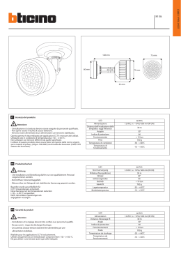
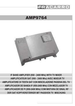
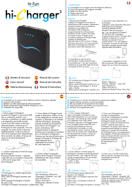
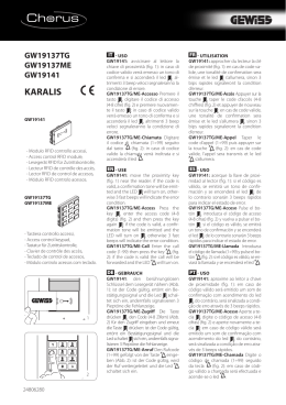
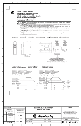
V2 S.p.A.
Corso Principi di Piemonte, 65/67
12035 RACCONIGI (CN) ITALY
tel. +39 01 72 81 24 11 - fax +39 01 72 84 050
[email protected] - www.v2home.com
IL n.381
EDIZ. 10/02/2015
SENSIVA-PLUS
I
GB
FOTOCELLULE DA PARETE ORIENTABILI (180°) E
SINCRONIZZATE (FINO A 8 COPPIE DI DISPOSITIVI)
WALL-MOUNTED PHOTOCELLS, ORIENTABLE (180 °) AND
SYNCHRONIZED (UP TO 8 PAIRS OF DEVICES)
F
PHOTOCELLULES DE PAROI ORIENTABLES (180°) ET
SYNCHRONISÉES (JUSQU’À 8 COUPLES DE DISPOSITIFS)
E
CÉLULAS FOTOELÉCTRICAS DE PARED ORIENTABLES (180°)
Y SINCRONIZADAS (HASTA 8 PAREDES DE DISPOSITIVOS)
P
FOTOCÉLULAS DE PAREDE ORIENTÁVEIS (180°) E
SINCRONIZADAS (ATÉ 8 PARES DE DISPOSITIVOS)
D
SCHWENKBARE (180°) UND SYNCHRONISIERTE
WANDSENSOREN (BIS ZU 8 VORRICHTUNGSPAARE)
NL
FOTOCELLEN MET (180°) RICHTBARE EN (TOT 8
INRICHTINGSSTELLEN) GESYNCHRONISEERDE WANDEN
Fig. 1
Fig. 2
Fig. 3
ITALIANO
DESCRIZIONE DEL DISPOSITIVO
La fotocellula SENSIVA-PLUS ha la possibilità di selezionare
8 codici di trasmissione differenti, permettendo quindi
l’installazione di 8 coppie di fotocellule affiancate senza pericolo
di interferenze.
Caratteristiche:
• Orientabili fino a 180° sull’asse orizzontale e 30° sull’asse
verticale
• Rallentamento automatico del rilevamento del segnale in caso
di neve per evitare interventi indesiderati causati dalla caduta
dei fiocchi
• Regolazione della portata su due livelli
• Led per semplificare la messa a punto del sistema
RICEVITORE (RX)
Codice di trasmissione: impostando
combinazioni diverse si possono ottenere
fino a 8 codici diversi.
TX e RX della stessa coppia devono avere
DIP-SWITCH 1 - 2 - 3
la stessa combinazione.
Più coppie nella stessa installazione
devono avere combinazioni differenti per
non interferire tra di loro.
DIP-SWITCH 4
Mantenere su ON
JUMPER J2
Posizione A - uscità relè con contatto
normalmente chiuso
Posizione B - uscità relè con contatto
normalmente aperto
INSTALLAZIONE A MURO (Fig.1)
Per una corretta installazione seguire attentamente le seguenti
istruzioni:
• Definire i punti previsti per l’installazione, tenendo conto che è
necessario fissare le fotocellule su una superficie lineare e piana.
m ATTENZIONE: posizionare le fotocellule in modo da
evitare che il ricevitore RX si trovi di fronte al sole.
• Definire il percorso dei canali per il passaggio dei cavi di
alimentazione.
• Aprire il contenitore della fotocellula e utilizzare la base A per
la tracciatura dei fori di fissaggio.
• Fissare la base A ed effettuare i collegamenti elettrici
COLLEGAMENTI ELETTRICI
TRASMETTITORE (TX)
1
alimentazione (+)
2
alimentazione (-)
RICEVITORE (RX)
1
alimentazione (+)
2
alimentazione (-)
3-4
uscita relè
- contatto NC con J2 in posizione A
- contatto NA con J2 in posizione B
MESSA A PUNTO
Terminata l’installazione verificare che il sistema funzioni
correttamente:
1. Controllare che nessun oggetto sia interposto tra il
trasmettitore e il ricevitore.
2. Alimentare il sistema:
- Il led del ricevitore è spento: la fotocellula non è centrata,
far oscillare lentamente la parte mobile fino a quando il led
del ricevitore si accende
- Il led del ricevitore è acceso: la fotocellula è centrata,
passare al punto 3
- Il led del ricevitore lampeggia lentamente: il segnale è
troppo debole, migliorare l’allineamento.
3. Inserire la cover B sulle fotocellule e verificare il corretto
fuzionamento senza togliere il filtro adesivo di attenuazione C
(il filtro simula condizioni metereologiche avverse come
pioggia, nebbia ecc.)
4. Togliere quindi il filtro di attenuazione.
5. Interrompere più volte il fascio infrarosso: il led del ricevitore si
deve spegnere e il relè deve commutare.
CARATTERISTICHE TECNICHE
Portata ottica
20 m
DIP-SWITCHES E JUMPER (Fig. 3)
Dimensioni
115x41x38 mm
Il dip-switch e i jumper presenti sui circuiti elettronici delle
fotocellule servono per impostare il funzionamento del sistema.
Alimentazione (VIN - GND)
12÷24 Vac / 12÷36 Vdc
TRASMETTITORE
Segnale
infrarosso modulato 2 KHz
l = 940 nm
Codice di trasmissione: impostando
combinazioni diverse si possono ottenere
fino a 8 codici diversi.
TX e RX della stessa coppia devono avere
DIP-SWITCH 1 - 2 - 3
la stessa combinazione.
Più coppie nella stessa installazione
devono avere combinazioni differenti per
non interferire tra di loro.
Portata relè
1A max 30 VDC
Assorbimento (VIN = 24Vdc)
TX 15 mA RX 20 mA
DIP-SWITCH 4
Mantenere su ON
Temperatura di funzionamento -20° + 60° C
Grado di protezione
IP54
DESCRIPTION OF THE DEVICE
The photocell SENSIVA-PLUS has the ability to select 8 different
transmission codes, thus allowing the installation of 8 pairs of
photocells side by side without danger of interference.
WALL INSTALLATION (Fig.1)
For correct installation, follow the instructions below very
carefully:
• Decide where the photocells are to be installed, taking into
account the need for the photocells to be fixed on a flat,
linear surface.
m PLEASE NOTE: position the photocells so as to avoid
the receiver RX facing into the sun.
• Decide where to place the channels for the power supply
cables.
• Open the photocell casing and use the base A to mark out
the positions of the fixing holes.
• Fix the base and connect-up the terminals.
WIRING
TRANSMITTER (TX)
1
power supply (+)
2
power supply (-)
RECEIVER (RX)
1
power supply (+)
2
power supply (-)
3-4
relay output
- relay output with NC contact - J2 Position A
- relay output with NO contact - J2 Position B
Transmission code: by setting different
combinations you can get up to 8
different codes.
TX and RX of the same pair must have
DIP-SWITCH 1 - 2 - 3
the same combination.
Multiple pairs in the same installation
must have different combinations to
avoid mutual interference
DIP-SWITCH 4
Keep on ON
JUMPER J2
Position A - relay output with normally
closed contact
Position B - relay output with normally
open contact
ADJUSTMENT
Having completed the installation, check that the system is
operating correctly:
1. Ensure there are no obstacles between the transmitter and
the receiver.
2. Power-up the system:
- The receiver LED is off: The photocell is not centred;
perform centring.
- The receiver LED is on: the photocell is centred, move on to
part 3.
- The led on the receiver blinks slowly: the signal is too weak;
improve the alignment.
3. Place the cover B over the photocell and ensure it is operating
correctly without removing the adhesive attenuation filter C
(the filter simulates adverse weather conditions such as rain,
fog etc.)
4. Then remove the attenuation filter.
5. Break the infrared beam a number of times: the receiver LED
must switch itself off and the relay must switch.
TECHNICAL SPECIFICATIONS
Optical range
20 m
DIP-SWITCHES AND JUMPERS (Fig. 3)
Dimensions
115x41x38 mm
The dip-switches and jumpers on the electronic circuits of the
photocells are used to set the operation of the system.
Power supply (VIN - GND)
12÷24 Vac / 12÷36 Vdc
Signal
infrarosso modulato 2 KHz
l = 940 nm
Relay contact
1A max 30 VDC
Absorption (VIN = 24Vdc)
TX 15 mA RX 20 mA
Operating temperature
-20° + 60° C
Protection degree
IP54
TRANSMITTER (TX)
Transmission code: by setting different
combinations you can get up to 8
different codes.
TX and RX of the same pair must have
DIP-SWITCH 1 - 2 - 3
the same combination.
Multiple pairs in the same installation
must have different combinations to
avoid mutual interference
DIP-SWITCH 4
Keep on ON
ENGLISH
Features:
• Adjustable up to 180° on the horizontal axis and 30° on the
vertical axis
• Automatic signal detection slow down in the event of snow to
avoid undesired activations caused by the fall of the flakes
• Maximum range adjustment on two levels
• Led to simplify the tuning of the system
RECEIVER (RX)
FRANÇAIS
DESCRIPTION DU DISPOSITIF
RÉCEPTEUR (RX)
La photocellule SENSIVA-PLUS a la possibilité de sélectionner 8
codes de transmissions différents permettant ainsi l’installation de
8 couples de photocellules côte à côte sans risque d’interférences.
Caractéristiques :
• Orientables jusqu’à 180° sur l’axe horizontal et 30° sur l’axe
vertical
• Ralentissement automatique de la détection du signal en cas
de neige pour éviter les interventions non désirées causées par
la chute des flocons
• Réglage du débit sur deux niveaux
• Led pour simplifier la mise au point du système
DIP-SWITCH
1-2-3
Code de transmission : en configurant des
combinaisons différentes, il est possible
d’obtenir jusqu’à 8 codes différents.
TX et RX du même couple doivent avoir la
même combinaison. Plusieurs couples dans
la même installation doivent avoir des
combinaisons différentes pour ne pas
interférer entre eux.
DIP-SWITCH 4
Maintenir sur ON
JUMPER J2
Position A - sortie relais avec contact
normalement fermé
Position B - sortie relais avec contact
normalement ouvert
INSTALLATION AU MUR (Fig.1)
Pour une correcte installation veuillez suivre attentivement les
instructions suivantes:
• Définir les points prévus pour l'installation, en tenant compte
qu'il est nécessaire de fixer les photocellules sur une surface
linéaire et plate.
m ATTENTION: positionner les photocellules de manière
d'éviter que le récepteur RX se trouve face du soleil.
• Définir le parcours des canaux pour le passage des câbles
d'alimentation.
• Ouvrir le boîtier de la photocellule et utiliser la base A pour le
traçage des trous de fixation.
• Fixer la base et effectuer les branchements au bornier.
BRANCHEMENTS ÉLECTRIQUES
ÉMETTEUR (TX)
1
alimentation (+)
2
alimentation (-)
RÉCEPTEUR (RX)
1
alimentation (+)
2
alimentation (-)
3-4
sortie relais
- sortie relais avec contact NF - J2 position A
- sortie relais avec contact NO - J2 position B
MISE AU POINT
Après avoir terminé la mise en place, vérifier que le système
fonctionne correctement:
1. Contrôler qu'aucun objet fixe ne soit interposé entre le
transmetteur et le récepteur.
2. Alimenter le système:
- la DEL du récepteur est éteinte: la photocellule n'est pas
centrée, exécuter le centrage.
- la DEL du récepteur est allumée: la photocellule est centrée,
passer donc au point 3.
- Le led du récepteur clignote lentement: le signal est trop
faible, améliorer l’alignement.
3. Insérer le couvercle B sur les photocellules et vérifier le
fonctionnement correct sans enlever le filtre adhésif
d'atténuation C (le filtre simule des conditions météo
adverses: pluie, brouillard etc..)
4. Enlever donc le filtre d'atténuation.
5. Interrompre plusieurs fois le faisceau infrarouge: la DEL du
récepteur doit s'éteinte et le relais doit commuter.
CARACTERISTIQUES TECHNIQUES
Portée optique
20 m
COMMUTATEURS DIP ET CAVALIERS (Fig. 3)
Dimensions
115x41x38 mm
Le commutateur dip et les cavaliers figurant sur les circuits
électroniques des photocellules servent à configure le
fonctionnement du système.
Alimentation (VIN - GND)
12÷24 Vac / 12÷36 Vdc
Signal
infrarouge modulé 2 KHz
l = 940 nm
ÉMETTEUR (TX)
Portée des contacts rélais
1A max 30 VDC
Absorption (VIN = 24Vdc)
TX 15 mA RX 20 mA
Temperature de fonctionnemento
-20° + 60° C
Protection
IP54
DIP-SWITCH
1-2-3
Code de transmission : en configurant des
combinaisons différentes, il est possible
d’obtenir jusqu’à 8 codes différents.
TX et RX du même couple doivent avoir la
même combinaison. Plusieurs couples dans
la même installation doivent avoir des
combinaisons différentes pour ne pas
interférer entre eux.
DIP-SWITCH 4
Maintenir sur ON
DESCRIPCIÓN DEL DISPOSITIVO
La célula fotoeléctrica SENSIVA-PLUS tiene la posibilidad de
seleccionar 8 códigos de transmisión diferentes, permitiendo por
lo tanto instalar 8 pares de células fotoeléctricas acopladas sin
peligro de interferencias.
Características:
• Orientables a 180º en el eje horizontal y 30º en el eje vertical
• Ralentización automática de la detección de la señal en caso
de nieve para evitar intervenciones no deseadas causadas por
la caída de los copos
• Regulación del alcance en dos niveles
• Testigo para simplificar la puesta a punto del sistema
RECEPTOR (RX)
Código de transmisión: ajustando
combinaciones diferentes se pueden
obtener hasta 8 códigos diferentes.
TX y RX del mismo par deben tener la
DIP-SWITCH 1 - 2 - 3
misma combinación.
Dos pares en la misma instalación deben
tener combinaciones diferentes para no
interferir entre sí.
DIP-SWITCH 4
Mantener en ON
JUMPER J2
Posición A - salida relé con contacto
normalmente cerrado
Posición B - salida relé con contacto
normalmente abierto
INSTALACIÓN EN MURO (Fig.1)
Para conseguir una instalación correcta siga atentamente las
siguientes instrucciones:
• Defina los puntos previstos para la instalación, teniendo en
cuenta que es necesario fijar las fotoceldas sobre una
superficie uniforme y plana.
m ATENCIÓN: coloque las fotoceldas a modo de evitar
• Defina el trayecto de los conductos para el paso de los cables
de alimentación.
• Abra el contenedor de la fotocelda y utilice la base A para el
trazo de las perforaciones de fijación.
• Fije la base y efectúe las conexiones a la placa de bornes.
CONEXIONES ELÉCTRICAS
TRANSMISOR (TX)
1
alimentación (+)
2
alimentación (-)
RECEPTOR (RX)
1
alimentación (+)
2
alimentación (-)
3-4
salida relé
- salida relé con contacto NC - J2 posición A
- salida relé con contacto NA - J2 posición B
Concluida la instalación compruebe que el sistema funciona
correctamente:
1. Inspeccione para garantizar que ningún objeto físico se
interponga entre el transmisor y el receptor.
2. Alimente el sistema:
- El diodo luminoso del receptor está apagado: la fotocelda
no está centrada, proceda a centrarla.
- El diodo luminoso del receptor está encendido: la fotocelda
está centrada, pase al punto 3.
- El testigo del receptor parpadea lentamente: la señal es
demasiado débil, mejorar la alineación
3. Inserte la cubierta B sobre las fotoceldas y compruebe el
funcionamiento correcto sin retirar el filtro adhesivo de
atenuación C (el filtro simula condiciones meteorológicas
adversas como lluvia, niebla, etc.)
4. Retire, por lo tanto, el filtro de atenuación.
5. Interrumpa varias veces el haz infrarrojo: el diodo del receptor
se debe apagar y el relé debe conmutar.
CARACTERÍSTICAS TÉCNICAS
Alcance óptico
20 m
DIP-SWITCHES Y JUMPER (Fig. 3)
Dimensiones
115x41x38 mm
El dip-switch y los jumpers presentes en los circuitos electrónicos
de las células fotoeléctricas sirven para ajustar el funcionamiento
del sistema.
Alimentación (VIN - GND)
12÷24 Vac / 12÷36 Vdc
Segnale
infrarrojo modulado 2 KHz
l = 940 nm
Portata relè
1A max 30 VDC
Absorción (VIN = 24Vdc)
TX 15 mA RX 20 mA
Temperatura de funcionamiento
-20° + 60° C
Grado de protección
IP54
TRANSMISOR (TX)
Código de transmisión: ajustando
combinaciones diferentes se pueden
obtener hasta 8 códigos diferentes.
TX y RX del mismo par deben tener la
DIP-SWITCH 1 - 2 - 3
misma combinación.
Dos pares en la misma instalación deben
tener combinaciones diferentes para no
interferir entre sí.
DIP-SWITCH 4
Mantener en ON
ESPAÑOL
que el receptor RX se encuentre de frente al sol.
PUESTA A PUNTO
DESCRIÇÃO DO DISPOSITIVO
A fotocélula SENSIVA-PLUS permite seleccionar 8 códigos de
transmissão diferentes, possibilitando a instalação de 8 pares de
fotocélulas dispostas lado a lado sem perigo de interferências.
Características:
• Orientáveis até 180° no eixo horizontal e 30° no eixo vertical
• Abrandamento automático da detecção do sinal em caso de
neve para evitar accionamentos indesejados causados pela
queda de flocos de neve
• Regulação da amplitude em dois níveis
• LED para simplificar a regulação do sistema
INSTALAÇÃO NA PAREDE (Fig.1)
Para uma correcta instalação observar atentamente as seguintes
instruções:
• Definir os pontos previstos para a instalação, considerando
que é necessário fixar as células fotoeléctricas numa superfície
linear e plana.
m ATENÇÃO: posicionar as células fotoeléctricas de
forma a evitar que o receptor RX fique de frente para o sol.
PORTUGUÊS
• Definir o percurso dos canais para a passagem dos cabos de
alimentação.
• Abrir o contentor das células fotoeléctricas e utilizar a base A
para o traçado dos furos de fixação.
• Fixar a base e conectar ao borne.
LIGAÇÕES ELÉCTRICAS
TRANSMISSOR (TX)
1
alimentação (+)
2
alimentação (-)
RECEPTOR (RX)
1
alimentação (+)
2
alimentação (-)
3-4
saída do relé
- saída de relé com contacto NF - J2 posição A
- saída de relé com contacto NA - J2 posição B
INTERRUPTORES DIP E JUMPER (Fig. 3)
O interruptor dip e os jumpers presentes nos circuitos
electrónicos das fotocélulas servem para configurar o
funcionamento do sistema.
TRANSMISSOR (TX)
Código de transmissão: definindo várias
combinações, é possível obter um
máximo de 8 códigos distintos.
O TX e o RX do mesmo par devem
DIP-SWITCH 1 - 2 - 3
possuir a mesma combinação.
Vários pares da mesma instalação devem
possuir combinações diferentes para não
interferirem entre eles.
DIP-SWITCH 4
Mantenere su ON
RECEPTOR (RX)
Código de transmissão: definindo várias
combinações, é possível obter um
máximo de 8 códigos distintos.
O TX e o RX do mesmo par devem
DIP-SWITCH 1 - 2 - 3
possuir a mesma combinação.
Vários pares da mesma instalação devem
possuir combinações diferentes para não
interferirem entre eles.
DIP-SWITCH 4
Mantenere su ON
JUMPER J2
Posição A - saída de relé com contacto
normalmente fechado
Posição B - saída de relé com contacto
normalmente aberto
AFINAÇÃO
Ao terminar a instalação verificar se o sistema funciona
correctamente:
1. Controlar que nenhum objecto fixo se interponha entre o
transmissor e o receptor.
2. Alimentar o sistema:
- O led do receptor está apagado: a célula fotoeléctrica não
está centrada, executar a centração.
- O led do receptor está aceso: a célula fotoeléctrica está
centrada, passar ao ponto 3.
- O LED do receptor pisca lentamente: o sinal é demasiado
fraco: melhorar o alinhamento
3. Inserir a cover B nas células fotoeléctricas e verificar o correcto
funcionamento sem retirar o filtro adesivo de atenuação C
(o filtro simula condições meteorológicas adversas como
chuva, neblina, etc.)
4. Retirar então o filtro de atenuação.
5. Interromper várias vezes o feixe infravermelho: o led do
receptor deve apagar e o relé deve comutar.
CARACTERÍSTICAS TÉCNICAS
Capacidade óptica
20 m
Dimensões
115x41x38 mm
Alimentação (VIN - GND)
12÷24 Vac / 12÷36 Vdc
Sinal
infravermelho modulado 2 KHz
l = 940 nm
Capacidade relé
1A max 30 VDC
Absorção (VIN = 24Vdc)
TX 15 mA RX 20 mA
Temperatura de funcionamento
-20° + 60° C
Protecção
IP54
BESCHREIBUNG DER VORRICHTUNG
Der Sensor SENSIVA-PLUS kann 8 verschiedene Sendecodes
auswählen, d.h. es können 8 Sensorenpaare gleichzeitig installiert
werden, ohne dass die Gefahr von Störungen besteht.
Merkmale:
• Auf der Horizontalachse bis zu 180° schwenkbar, auf der
Vertikalachse bis zu 30°.
• Automatische Verzögerung der Signalerfassung bei Schnee,
um ein ungewolltes Ansprechen bei Schneefall zu vermeiden.
• Einstellung der Reichweite auf zwei Stufen.
• Led für eine vereinfachte Systemeinstellung.
EMPFÄNGER (RX)
Sendecode: Durch die Eingabe
verschiedener Kombinationen können bis
zu 8 verschiedene Codes erstellt werden.
TX und RX ein und desselben Paares
DIP-SWITCH 1 - 2 - 3 müssen die gleiche Kombination haben.
Mehrere Paare, die gemeinsam installiert
sind, müssen mit verschiedenen
Kombinationen versehen werden, damit
zwischen ihnen keine Störungen auftreten
DIP-SWITCH 4
Auf ON behalten
JUMPER J2
Stellung A - Relais-Ausgang mit
Öffnerkontakt
Stellung B - Relais-Ausgang mit
Schließerkontakt
WANDMONTAGE (Abb.1)
Für eine korrekte Installation aufmerksam folgende Hinweise
befolgen:
• Die zur Installation vorgesehenen Punkte bestimmen und
dabei berücksichtigen, dass die Fotozellen auf einer linearen
und ebenen Oberfläche befestigt werden müssen.
m ACHTUNG: die Fotozellen so positionieren, dass sich
der Empfänger RX der Sonne gegenüber befindet.
• Den Verlauf der Kabeldurchgänge für die Stromversorgung
festlegen.
• Das Gehäuse der Fotozelle öffnen und die Basis A zum
Anreißen der Befestigungslöcher benutzen.
• Die Basis befestigen und die Anschlüsse am Klemmenbrett
vornehmen.
STROMANSCHLÜSSE
SENDER (TX)
1
Stromversorgung (+)
2
Stromversorgung (-)
Nach der Installation prüfen, ob das System korrekt funktioniert:
1. Sicherstellen, dass sich kein fester Gegenstand zwischen
Sender und Empfänger befindet.
2. System mit Strom versorgen:
- Das LED des Empfängers ist ausgeschaltet: Fotozelle ist
nicht zentriert. Zentrierung vornehmen
- Das LED ist eingeschaltet: die Fotozelle ist zentriert, zu
Punkt 3 übergehen.
- Die Led des Empfängers blinkt langsam: das Signal ist zu
schwach. Entweder die Ausrichtung verbessern
3. Abdeckung B auf die Fotozelle setzen und auf korrekten
Betrieb prüfen, ohne den selbstklebenden Abschwächungsfilter
C zu entfernen (der Filter simuliert ungünstige meteorologische
Bedingungen wie Regen, Nebel usw.)
4. Danach den Abschwächungsfilter entfernen.
5. Mehrmals den Infrarotstrahl unterbrechen: das LED des
Empfängers muss sich ausschalten und das Relais muss
umschalten.
TECHNISCHE EIGENSCHAFTEN
Optische Leistung
20 m
DIP-SWITCHES UND JUMPER (Abb. 3)
Masse
115x41x38 mm
Der Dip-switch und die Jumper, die in den elektronischen
Schaltkreisen der Sensoren vorhanden sind, dienen zur
Einstellung der Systemfunktionen.
Stromversorgung (VIN - GND)
12÷24 Vac / 12÷36 Vdc
Signal
Moduliertes Infrarot
2 KHz l = 940 nm
SENDER (TX)
Leistung Kontakte Relais Empfänger 1A max 30 VDC
Sendecode: Durch die Eingabe
verschiedener Kombinationen können bis
zu 8 verschiedene Codes erstellt werden.
TX und RX ein und desselben Paares
DIP-SWITCH 1 - 2 - 3 müssen die gleiche Kombination haben.
Mehrere Paare, die gemeinsam installiert
sind, müssen mit verschiedenen
Kombinationen versehen werden, damit
zwischen ihnen keine Störungen auftreten
DIP-SWITCH 4
Auf ON behalten
Stromaufnahme (VIN = 24Vdc)
TX 15 mA RX 20 mA
Betriebstemperatur
-20° + 60° C
Schutzart
IP54
DEUTSCH
EMPFÄNGER (RX)
1
Stromversorgung (+)
2
Stromversorgung (-)
3-4
Relaisausgang
- Relais-Ausgang mit Öffnerkontakt - J2 Stellung A
- Relais-Ausgang mit Schließerkontakt - J2 Stellung B
EINSTELLUNG
BESCHRIJVING VAN DE INRICHTING
De fotocel SENSIVA-PLUS heeft de mogelijkheid 8 verschillende
verzendingscodes te selecteren, zo de installatie toelatend van 8
stellen fotocellen die parallel lopen zonder het gevaar op
interferenties.
Kenmerken:
• Richtbaar tot 180° op de horizontale as en 30° op de
verticale as
• Automatische verlangzaming van de opsporing van het signaal
in geval van sneeuw om ongewenste ingrepen veroorzaakt
door de val van vlokken te voorkomen
• Afstelling van het draagvermogen op twee niveaus
• Led voor het versimpelen van het afstellen van het systeem
ONTVANGER (RX)
Verzendingscode: door verschillende
combinaties in te stellen kunnen er tot 8
verschillende codes verkregen worden.
TX en RX van hetzelfde koppel moeten
DIP-SWITCH 1 - 2 - 3
dezelfde combinatie hebben.
Meerdere koppels in dezelfde installatie
moeten verschillende combinaties
hebben om niet onderling te interfereren
DIP-SWITCH 4
Op ON houden
JUMPER J2
Positie A - relaisuitgang met normaal
gesproken gesloten contact
Positie B - relaisuitgang met normaal
gesproken open contact
INSTALLATIE OP DE MUUR (Afb.1)
Volg onderstaande instructies met aandacht voor een correcte
installatie:
• Stel de punten vast die voor de installatie voorzien zijn, rekening
houdend met het feit dat de fotocellen op een rechtlijnig en
vlak oppervlak bevestigd moeten worden.
m LET OP: breng de fotocellen zo in positie dat
vermeden wordt dat ontvanger RX zich recht in de zon
bevindt.
• Stel het traject van de kanalen vast voor de passage van de
kabels van de voedingsunit.
• Open de houder van de fotocel en gebruik basis A voor het
traceren van de bevestigingsgaten.
• Zet basis A vast en breng de aansluitingen op de
klemmenstrook tot stand.
ELEKTRISCHE VERBINDINGEN
NEDERLANDS
ZENDER (TX)
1
voeding (+)
2
voeding (-)
ONTVANGER (RX)
1
voeding (+)
2
voeding (-)
3-4
uitgang relais
- relaisuitgang met NG contact - J2 positie A
- relaisuitgang met NO contact - J2 positie B
DIP-SWITCHES EN JUMPER (Fig. 3)
De dip-switch en de jumper die zich op de elektronische circuits
van de fotocellen bevinden dienen voor het instellen van de
werking van het systeem.
ZENDER (TX)
Verzendingscode: door verschillende
combinaties in te stellen kunnen er tot 8
verschillende codes verkregen worden.
TX en RX van hetzelfde koppel moeten
DIP-SWITCH 1 - 2 - 3
dezelfde combinatie hebben.
Meerdere koppels in dezelfde installatie
moeten verschillende combinaties
hebben om niet onderling te interfereren
DIP-SWITCH 4
Op ON houden
FIJNAFSTELLING
Is de installatie klaar, controleer dan of het systeem correct werkt:
1. Controleer of geen enkel object tussen de zender en de
ontvanger staat.
2. Voed het systeem:
- De led van de ontvanger is uit: de fotocel is niet
gecentreerd, voer de centrering uit.
- De led van de ontvanger brandt: de fotocel is gecentreerd,
ga over naar punt 3.
- De led van de ontvanger knippert langzaam: het signaal is
te zwak, de uitlijning verbeteren.
3. Plaats cover B op de fotocellen en controleer de correcte
werking zonder het zelfklevende verzachtende filter C weg te
nemen C (het filter simuleert de weersomstandigheden zoals
regen, mist, enz.).
4. Neem dit filter vervolgens weg.
5. Onderbreek meermalen de infrarood bundel: de led van de
ontvanger moet uitgaan en het relais moet omschakelen.
TECHNISCHE KENMERKEN
Optisch bereik
20 m
Afmetingen
115x41x38 mm
Voeding (VIN - GND)
12÷24 Vac / 12÷36 Vdc
Signaal
Gemoduleerd infrarood 2 KHz
l = 940 nm
Bereik relais
1A max 30 VDC
Absorptie (VIN = 24Vdc)
TX 15 mA RX 20 mA
Bedrijfstemperatuur
-20° + 60° C
Bescherming
IP54
DICHIARAZIONE DI CONFORMITÀ
DECLARAÇÃO DE CONFORMIDADE
V2 S.p.A. dichiara che le apparecchiature SENSIVA-PLUS sono
conformi ai requisiti essenziali fissati dalle direttive:
• 2004/108/CE compatibilità elettromagnetica
• RoHS2 2011/65/CE
V2 S.p.A. declara que as aparelhagens SENSIVA-PLUS são
conformes aos requisitos essenciais estabelecidos pela directiva:
• 2004/108/EC compatibilidade electromagnética
• RoHS2 2011/65/EC
e che sono state applicate le seguenti norme tecniche:
• EN 61000-6-2
• EN 61000-6-3
e que foram aplicadas as seguintes normas técnicas:
• EN 61000-6-2
• EN 61000-6-3
Racconigi, 14/06/2012
Il rappresentante legale V2 S.p.A.
Cosimo De Falco
Racconigi, 14/06/2012
O representante legal V2 S.p.A.
Cosimo De Falco
DECLARATION OF CONFORMITY
KONFORMITÄTSERKLÄRUNG
V2 S.p.A. hereby declare that SENSIVA-PLUS equipment conforms
to the essential requirements established in directives:
• 2004/108/EC electromagnetic compatibility directive
• RoHS2 2011/65/EC
V2 S.p.A. erklärt, dass die Geräte SENSIVA-PLUS konform mit den
wesentlichen Bestimmungen der Richtlinie:
• 2004/108/EC über die elektromagnetische Kompatibilität
• RoHS2 2011/65/EC
and that the following technical standards have been applied
• EN 61000-6-2
• EN 61000-6-3
sind und dass folgende technische Normen berücksichtigt wurden:
• EN 61000-6-2
• EN 61000-6-3
Racconigi, 14/06/2012
Legal representative, V2 S.p.A.
Cosimo De Falco
Racconigi, 14/06/2012
Gesetzlicher Vertreter der V2 S.p.A.
Cosimo De Falco
DÉCLARATION DE CONFORMITÉ
VERKLARING VAN OVEREENKOMST
V2 S.p.A. déclare que les produits SENSIVA-PLUS sont conforment
aux qualités requises essentielles fixées par la directive :
• 2004/108/EC Compatibilité Électromagnétique
• RoHS2 2011/65/EC
V2 SPA verklaart dat de SENSIVA-PLUS producten voldoen aan de
essentiële vereisten die door de volgende richtlijnen bepaald zijn
• 2004/108/EC Richtlijn EMC
• RoHS2 2011/65/EC
et que les normes techniques suivantes ont été appliquées
• EN 61000-6-2
• EN 61000-6-3
en dat de volgende technische normen toegepast zijn:
• EN 61000-6-2
• EN 61000-6-3
Racconigi, le 14/06/2012
Le représentant légal V2 S.p.A.
Cosimo De Falco
Racconigi, 14/06/2012
De rechtsgeldig vertegenwoordiger van V2 S.p.A.
Cosimo De Falco
DECLARACIÓN DE CONFORMIDAD
V2 S.p.A. declara que los productos SENSIVA-PLUS cumplen los
requisitos esenciales establecidos por las siguientes directivas:
• 2004/108/EC Compatibilidad electromagnética
• RoHS2 2011/65/EC
y que son aplicadas las siguientes normas técnicas
• EN 61000-6-2
• EN 61000-6-3
Racconigi, 14/06/2012
El representante legal de V2 S.p.A.
Cosimo De Falco
Baixar