NEUTRON VELOCITY SELECTOR OF THE INSTITUTO DE
ENERGÍA ATÓMICA MECHANICAL DESIGN AND
ELETRONIC CONTROL
RAUL BRENNER and R. L. ZIMMERMAN
Publicação
I EA N.°
Dezembro — 1964
7e
INSTITUTO DE ENERGIA ATÔMICA
Caixa Postal 11049
(Pinheiros)
CIDADE UNIVERSITÁRIA "ARMANDO DE S A L L E S OLIVEIRA"
SÃO P A U L O — BRASIL
NEITROU VELOCITY SELECTOR OF TEE INSTITUTO M
ENEEGIA ATClIfA
MECHANICAL DESIGN AND ELETRONIC CONTROL
by
Ro Brenner and RoL» Zimmerman
(*)
INSTITUTO DB ENERGIA ATÔMICA •
são Paulo - Brasil
Publicação lEA
December -
nß 7 6
I964
Presented at the Study Group Meeting on the.Utilization
of
Research Reactors, Sao Paulo, November 19^3»
(*) IAEA visiting scientist, on leave from Case Institute of
Technology, Cleveland, Ohio, USA,
Comissão Nacional de Energia Nuclear
Presidentes Profo Luiz Cintra do Prado
Universidade de Sao Paulo
Reitorg Profo Luiz Antonio da Gama e Silva
Instituto de Energia Atômica
Diretor? Profo Romulo Ribeiro Pieroni
Conselho Tecnico-Científico do lEA
Profo
José Moura Gonçalves '
" pela USP
Profo
Francisco João Humberto Maffei
Profo
Rui Ribeiro Franco
" pela GNEN
Profo Theodoreto
Holo
de Arruda Souto
Divisões Didático-Científicaas
DiVo de Física Nuclears Profo Marcello DoSo Santos
DiVo
de Engenharia de Reatores? Profo Paulo Saraiva de Toledo
DiVo de Ensino e Formação? Profo Luiz Cintra do Prado
DiVo
de Radioquímica? Profo Fausto Walter de Lima
DiVo
de Radiobiologia? Profo Romulo Ribeiro Pieroni
DiVo
de Metalurgia Nuclear? Profo Tharciaio D o S o u z a Santos
DiVo
de Engenharia Químicas Profo Pawel Krumholz
NEUTRON TELOCITY SELECTOR OP THE INSTITUTO DE EMERGIA ATÔMICA
MECHANICAL DESIGN AND ELECTRONIC CONTROL
R„
Brenner and
RoLo
Zimmerman
INSTITUTO DE EMERSIA ATïMlCA
São Paulo
Brasil
Resumo
Foi construído no Instituto de Energia Atânica^ um seletor de velocidade
para neutrons* tipo Permi, a fim de eliminar reflexSes de ordem superior
n-m monocromador de cristal e também tendo era vista e3Q)eriéhciás nas quais
ê necessário ura feixe de neutrons lentos de alta intensidadeo
O
r0tor_
foi idealizado para selecionar neutrons muito lentos^ ainda que a resoluçSo seja pobres visando a obtenção de vm feixe intensoo
Tomaram-se provi^
dêhcias para se reduzir o background de neutrons e_ralos gamao
Apresenta-se o seu projet© mecâaicos acrescentando-se algumas considera çSes quanto ao projeto dos rolamentoso
& descrito o sistema automático de
contrôle de velocidade, que consiste de um motor
DoCe
de 5
do por ura retifieador trifásico^ controlável^ a thyratrí^So
HePos
alimenta-
A velocidade
ê controlada por um sistema eletr^ico com realimentaçâo negativa»
A esta
bilidade, em pequenos intervalos de tempo, ê cerca de 0^5^ depois do aquecimentOo
No começo da operação, é fornecida uma corrente constante»
Résumé
On a construit à l'Instituto de Energia AtÔtoica un. sélecteur de vitesse
pour neutrons, type Permi, pour éliminer les reflexions d'ordre supérieur
dans un monocbromateur à cristal et aussi destiné à des expériences où on
('«') IAEA visiting scientist, an leave from Case Institute of Tecimology,
Cleveland, Ohio, USA»
a besoin d'm faisceau de neutrons lents de haute Intensité»
Le rotor a
êîê projeté pour sélectionner neutrons très lents, bien que la résolution
soit pauvre, ayant pour but l'obtention d'un faisceau intense»
On a pris
d^s mesures pour réduire le bruit de fond de neutrons et de rayonnements
gammao
On présente son projet mécanique et on ajoute quelques considérations sur
le projet des roulements»
On décrit le système automatique de contrôlé
dé vitesse, qui consiste dans un moteur
D»Co
â
5
HeP» alimenté par
rétifieateur tripliasique, contrôlable, â thjrratronso
La vitesse
contrôlée par un système électronique avec réalimentation négative»
siabilité dans de petits intervalles de temps est de 0 , 5 ^ après
réchauffement0
un
est
La
le
Au commencement de l'opération, on fctumit un courant
constant»
Abstract
A Perraisïtype neutron velocity selector was constructed at the Institut©
de Energia AtÔhiiea (lEA) to eliminate higher order reflections in
a
crystalraonochromatorand for experiments where high intensity beams of
very slow neutrons are required^
The rotor has been designed to select
very slow neutrons, although with poor resolution, in an effort to obtain
an intense beam»
backgroundo
Provisions were made to reduce neutron and gamma
ray
The mechanical design is described and some considerations
about the bearings design are added»
is; described,and consists of a
5
three-phase thyratron rectifier»
after ïiam-up»
HP
The automatic speed control system
DoGo
motor powered by a controlled
The short term stability is about OoS^
For star-b-up, a constant current of operation is featured»
BITRODUCTION
lEA has a small neutron spectrometer (built from sn x-ray monoehromator)
whâ-ch has been used in the last tvro years to measure •the slow neutron total
cross section for some rare earth éléments»
Every crystal monoehromator
has the problem of contamination of the neutron beam ^vith energies higher
than that of the first order Bragg reflected neutrons. These higher
order reflections occur at energies 4 E Q , 9EQ, . . O vjhere
is
the
first order energy usually desirable.
One v/ay to eliminate the undesirable neutrons is to pass the beam
(either before or after the Bragg reflection) through a Fermi-type
mechanical velocity selector. Such selector cannot conveniently
be
made with high enough resolution to replace the crystal monoeiriromator
entirely, but their use make tlie possible elimination of unvjanted
orders with a relatively lov; loss in intensity of the first
order
neutrons »
For this purpose, and for certain other experimeats vdiere
high
intensity beams of vei^ slow neutrons are required, a Fermi mechanical
velocity selectoî'» vra,s constmcted at X M ,
the mechanical design is described.
In the section that follows,
In later sections, the operating
characteristics and electronic controls are described^
DESIGN
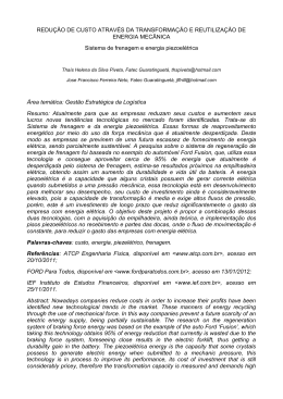
Figure 1 shows a schematic of the rotor. The shaft (horizontal at
lEA) is a 4,'5 ijich diameter steel shaft id.th multiple bearings
about
3 6 inches betvreen centers. The bearings are mounted in rubber nrhich
serves to align the bearings and to damp out vibrations. The bearings
are cooled by circulating oil,
'
The neutron beam is defined by 30 slotted dJ.sks equally separated by
29 plastic spacers. Each steel disk has 5 6 slots, each of them having
3 / ^ X 1 inch, Tliese disks may be arranged to define the neutron velocity
with the resolution required by a pax-i;icular experiment.
The rotor is operated in a vacuum cf about 1000 microns Hg in
order
that the power dissipation is not excessive^' The peripheral speeds are
less than the velocity of sound, so that the residual air doss not heat
the rotoro
The bearings are commercial high speed ball bearings rated for continuous
service at l^OOOrpmo
The rotor has operated routinely at speeds up
to
1 1 Ò 0 0 rpm with vibi-ational amplitudes completely negligible, and with
no
beairing failiu'eso
of
The individual disks were balanced before assembly
the rotor to assure vibration free operation at high speedo
The resonances
in 'the loaded shaft are at frequencies much higher -tíian the design maximum,
which is
15000
rpm»
The numbex' of neutrons transmitted by this rotor when adjusted for
velocity resolution (—.2. , where
V is the full width
a
of the transmitted
V
„ 2 0 Is given by the egression
spectrum at naif height) of
2o3
X
10'
C
S
>
s
where
probable
is the ratio of the trmismitted neutron velocity to the most
velocity (defined oy 1/2 ravi = kT)o
Conditions at the lEâ reactor
2
are arranged so that a radiatiiig surface of about 1 2 in
is available > near
the center of the reactor core about I 5 0 inches from the velocity selector.
The reactor flvx there is
2o5
x lO-'-^ ra /cm^/sec»
,
The background comting rate in a direct beam .experiment is designed
to be less than about 1 comt/rainute using a proportional counter of dimensions
1 / 2 inch diameter by 1 - 1 / 2 inch long, filled with '(0 cm BP-j gas trlth
«irichement. Such a deteetcir is essaitially 1 0 0 ^ efficient for
who$e velocities are less than 1/20 thermale
no
neutrons
The efficlaacy for detecting
neutrons of thermal energies is less than ^o. The background of 1 count/
minute was chosen as comparable to that normally escpected from natural
racM-oactivity in the detector walls,
Besides choosing a detector whose efficiency is low for neutrons
of
thermal energies, the limit of background also dictates the amount
©f
steel in the rotor necessary to attenuate the high flux of epi-thermai
neutronso
Using the numbers already glvaa, the amount of steel required
is 7 e 5 inchesc
Because approximately half the steel in the disks is cut
away to form slots, the rotor was designed with 3 0 2/2-lneh disks
giving
T o S inches of steel in the path of a neutron vtaose velocity is fast cougar
ed to the velocity being selected. The steel disks were cadmiiirn plated
to stop neutrons of velocities slightly above or below the selected
velocity. The cadmium also serves to absorb neutrons themalized in the
apparatus, neutrons which might otherwise multiply scatter into
the
detectors,
A plastic stator (not shown In the schematic) was foiroed from
30
plastic plates, formed In such a way thE^ every alternate plate occupied
the region between the steel disks. Slots were cut straight through
these interleaving plates so that no neutrons could pass
outside
the
rotor teeth. The rotor-stator spacing was 1 < , 0 mm over the full length of
the rotor and over about 1 / 5 of the periphery of each steel disk.
In the design, every effort was made to reduce the flux of fission
neutrons, epi-Cd neutrons, thermal neutrons, and reactor gamma rays. It
is thought to be possible to perform direct beam experiments with neutrons
whose energy is a factor 1 0 0 less than thermal with a counting rate
comparable to the backgromd, that is, 1 count per minute.
Figure 2 shows the number of neutrons per second transmitted for each
rotor velocity, when the rotor is adjusted for a resolution ofAY. = , 2 0 ,
For low velocity, this curve is also the direct beam counting rate, and
the dashed curve shows the counting rate in a proportional detector fill
ed with 7 0 em normal BF^
(Antcai 8 2 1 ) ,
The rotor has been designed to select very slow neutrons with
poor
resolution with an effort to increase the intensity»
It is easy
to
readjust the steel disks so that a smaller slot is defined (by staggering
alternate disks) and in this way neutrons of energies higher tliàn thermal
may be selected at practical rotor velocities,. Of cource this method of
1.
adapting the rotor for higher velocity neutrons reduces the latensity in
proportion to the square of the reduction of the slit width, but
near
the peak of the î-toîeHian. intensity is no problem in a direct beam
experimento
ElECTROHie SPEED COIWROL
The rotor of the selector is powered by a standard 5 HeP» 220 V DC
shunt motor through a V belt systèmeAt the maximum speed (10»000 rpm
the rotor), the motor is run, at about 2000 rpm and
ahd field 0
in
250 V in the armature
Tliis is about 20^ overdrive but is not detrimental to
the
motor o
The speed contP'ol is made through the armature current fed by a tri-pîiase. rectifier»
The thyratrons are of the Phillips type PL105 with power supplied from
aferi-pliaseline xdLth 220 V phase-neutràl»
by a variable
Each "bhyratron is controlled
time delay circuit that provides a turn-on trigger pulse
with a delay, related to the beginning of the positive part of the wave»
This delay is controlled by the voltage furnished by a DoC» amplifier, so
r
that a variable portion of the positive wave may be rectified giving thus
a continuously variable rectified power from zero to the maximujiio
'The speed control is doxie by negative feedback, with a speed sensing
device, an operational amplifier and the above described controlled poirer
rectifierc
The speed sexssing is done by an AoC» generator attached to the rotor
7
shaft, whose signal is rectified after passing through a current transformer
that gives a direct current proportional to the speed. This cvirrent
is
subtracted from a fixed reference current and fed to a D c C , amplifier
of
current feedback type. The speed is adjusted by a precision potentiometer
in the generator circuit, ii?hich controls the generated current. This sens
iTig system was a lov/ cost temporary solution, to be replaced later by
a-4D«C«
tachometer„generator.
The stability is good for short periods
(^0,5^
in
30
mini)showing
a
steady drift for iäie first 3 0 minutes, which is attributed to temperature
effects in the resistance of the generator circuit.
To calibrate and monitor the speed, a scaler is used to count
the
number of generator cycles for a given period of. time.
For the start-up, an armature current feedback system that by-passes
the speed control is used, supplying to the armature a constant manually-controlled cia=rent, independent of the speed, A null indicator is used
to show vthen the speed has reached the desired control point.
The control system was built in two separate units as can be seen
in
the block diagram,'
SOm PROBLEMS RELATED TO THE BEARINGS DESIGN
In the first design, the bearigns were mounted rigidly on the housing
which is a heavy and rigid structure. Since the rotor is heavy and
the
shaft very short and rigid, this mounting created two important problems^
l) The rotor unbalance, xvhich is not too small and difficult to eliminate
as a result of the multi-parts structure of the rotor, developed a strong
vibration that consumed excessive energy with evident danger to the system.
V
Neutral
CONTROL
H
@ Ground
BLOCK
DIAGRAM
PL 103
PL 103
R@eiifier
coE«TRot
mfUfim
chassis
0-8S0V
skov
0. c.
Refereftee
Current
<-—
PO^ER
CHASSIS
GURRANT
I
I
o-i
ROTOR
mton
2) The ball bearlags shovred a rapid deterioration owing to the increased
vibrational load and also due to higli speeds and rigid mounting.,
the
bearing tracks svirface tending to deteriorate. Thus a flexible moiaiting
was decided on, with a vibrating mass attached to the beai'ing as small
as possible. Each bearing consists of a pair of Sl^ 6205 ball bearings
n
encased in
8 cms, diameter, 1 0 cms, long iron cylinder with an
oil
seal at each bearing. This cylinder was mounted in a cylindrical hole
in the housing, with an anular spacing of approximately 6 mm and
two
neoprene "o" rings tightly inserted into the spacing.
The space betxireen the ball bearings is filled with oil, which is
circulated through a v^ter heat exchanger by a pump, the latter directly connected to the rotor system
in order to prevent overheating follovj-^
tng an eventual power failure.
This mounting was very effective, the sj'stera having a single broad
resonant frequency of about
3500
rpm with good damping, no noise, and
at other speeds the vibration having disappeared almost completely, even
vdth the rotor not finely balanced.
AciaraïLSDGsr'ïEœ?s
The authors vd.sh to express their gratitude to the TEA machine shop,
and particularly to Ivfi^, José Perrelra, without whose competence and
good
this apparatus could not have been designed and built. Our
thanlcs also to Pedro Bento Camargo \<jho vieil
organized the work
had to be done in various SSto Paulo industries.
which
10^
10«
ilâM
Of
VELSCiTY
iWTEMSITY
JgLECyOSI. AT
:!0
"» .to
10'
10.'8
10
10r4
id*
lo"^ i d '
WeUTBOM
I
VELOCITY
10
CRATie
TO
«esf^ Î
(A)—
8KF
BEARINGS
8-205
MA
B80MZE
TB
wtsm
HETAlWeR
29>8
1.0. 2S a>«
0.0. 82 mm
o
.30 BLADES - (8MCERS NOT SHOWN)
4.B0,R
r .ooS
\ 38 SLOTS
.378 s 1.00
EQUALLY SPACED
APPROXIMATE
WEI«MT
, ^ (ALIIIIIMUM
SPACeilS)
^SISE
,3 JULY I £81
Baixar