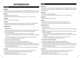
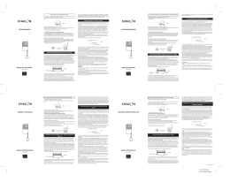
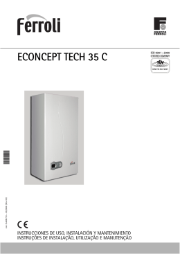
English - User Guide models BR1 - BR14 - BR7
close as possible to the vertical center line
of it (fig.9A and 4). If the screen has a
convex back lid supplements should be
added (fig.6), but it is better not to use
any supplements (fig.5). If the TV has a flat
back lid supplements will not be
necessary.Make sure that the proper
screws or bolts are utilized since the kit
contains several of different sizes (fig.1G,
H, I and J). Always use the correspondent
size washers (fig.1A and E).
BRACKET INSTALLATION
Audiovisual Equipment
UNIVERSAL BRACKET MOUNT FOR FLAT
PLASMA/LCD/TV USER GUIDE
BR-1FT from 37” to 63”
BR-14FT from 30“ to 55”
BR-7FT from 23” to 42”
Beware of plaster covered walls. If not sure
as to the strength of wall and / or the
correct procedure to fix this product call a
qualified professional fitter.
Before drilling, make sure that no electric
wiring, water pipes, or any other elements
may be damaged by the fitting.Wear eyes
and/or hear protection gear and use
proper tools correctly. At least two people
should work on the installation. The kit with
HANGING THE TV SCREEN
all the elements to install the brackets is
protected by a nylon or plastic film which
Do not exceed size and weight limits of
should be kept from children, as should
the brackets.
any small piece of hardware provided.
LOCH support brackets allow the screen to
be hanged with a 0º to 5º tilt. Use the metal
INSTALLATION MANUAL
spacers provided (fig.1L). Fix them with the
The LOCH BR-1FT/BR-14FT/BR-7FT wall
screws and autoblocking nuts (fig.1M). Figure
bracket was designed to keep flat TV
3 shows the final position of a tilted set. To
screens close to the wall with excellent
hang it parallel to the wall see figure 2.
aesthetic finish. This Universal Flat Wall
Slide the metal brackets along the base
Mount can hold virtually any 37” to 63” for plate to desired position and before letting
BR-1, 30” to 55” for BR-14 and 23” to 42”
it go check solidity of the fixing. Carefully
for BR-7 flat panel screen. It is easy to
insert the security bar (fig.1N). Screen can
install and is the perfect companion for
also be secured by using a padlock (fig.9B).
your Plasma LCD TV set.
GENERAL SPECIFICATION
INSTALLATION ON BRICKWORK WALLS
* This product can hold 37” to 63” for BR-1FT,
Use the support base plate to mark the
30” to 55” for BR-14FT and 23” to 42” for
wall for drilling (fig.10). Make sure that
BR-7FT Plasma LCD TV.
the marks of the middle horizontal line
* Adjustable by sliding laterally on wall.
of holes are leveled.
Screens can be tilted in a 0 to 5 degree
Drill the six holes in the wall. They should angle from vertical walls.
be 10 mm in diameter and 60 mm deep.
* Security lock bar and padlock feature available.
Insert a 10 mm plastic plug, “Fisher”
* Accessories provided: Screws, bolts,
type, in each hole (fig.1C) and fix the
nuts, washers.
base plate by using the appropiate size
LIABILITY LIMITS
bolts or screws (fig.1B) with their metal
washers (fig.1A).
IMPORTANT: LOCH has made every effort
to provide accurate and detailed instruction
INSTALLATION ON HOLLOW WALLS
for this product’s assembly and installation.
The base plate should be bolted or screwed Should you have any doubts consult a
firmly to the wood frame of the wall. To find qualified professional fitter.
the vertical pieces of the frame a sensor
LOCH recognizes no liability for any
may be used. A small hole may be punched difficulty or problem derived from the
thru the surface to detect the position of
interpretation of these instructions. These
the vertical pieces of wood (fig.7). Drill a 4
brackets and all their parts and accessories
mm in diameter and 3 mm deep hole in the must only be used for the purpose they
wood and screw or bolt the base plate from have been constructed.
its upper holes while checking the level.
LOCH, its commercial distributors and
Now use the base plate to mark the place retailers are not, directly or indirectly,
of lower holes.Fix the base plate using
responsible for any damage to persons and
screws and washers (fig.1A and 1B).
or properties derived from the use of this
product in an unsafe or different way for
FITTING SCREEN TO THE BRACKETS
which it has been designed and constructed.
Several parts of this product are small
Support brackets should be at the same
pieces of hardware therefore extreme care
height from the top of the screen and as
should be taken to keep them from children.
c.
Fig.2
Fig.1
Fig.3
Español - Guia de Usuario modelos BR1 - BR14 - BR7
PRECAUCIONES
* Utilice anteojos de protección para la instalación.
Proteja sus ojos.
* Use herramientas adecuadas.
* Es aconsejable que en la instalación participe mas
de una persona.
* El soporte viene provista de un nylon protector,
esto no es un juguete, mantenga a los niños alejados.
INSTALACION
Preste atención a las instrucciones de instalación.
Este producto fue diseñado para montar LCD
Plasma TV cercano a una pared vertical. Si no esta
seguro del material de la pared o como realizar la
instalación, consulte a un instalador profesional.
Antes de hacer algún agujero verifique que la
pared no tenga en su interior cables de luz,
caños de agua u otro objeto que se pueda dañar.
INSTALACION EN CONCRETO
Use el soporte de pared como plantilla (Figura 10)
marque 6 agujeros en la pared con un lápiz. Deben
marcarse tres arriba y tres abajo, en los costados
y en el centro. Verifique que las marcaciones y la
plantilla estén a nivel. Taladre los agujeros de 10
mm en la pared de tal manera que tengan por lo
menos 60 mm de profundidad. Inserte los tarugos
(Figura 1C). Presente el soporte y fijelo con el
tornillo (Figura 1B) y la arandela (Figura 1A).
INSTALACION EN PARED DE PLACA
El soporte debe estar fijado a dos rieles de madera.
Utilice un sensor de rieles para encontrarlos dentro
de la pared. Verifique que haya realmente un riel de
madera con un pequeño agujero o palpando con un
punzón (Figura 7). Agujeree 3 mm de profundidad
en cada riel con una mecha de 4 mm. Use el
soporte como plantilla para marcar los agujeros
inferiores verificando previamente este a nivel.
Fije el soporte usando los tornillos y arandelas
(Figura 1A y 1B).
MONTADO DE RIELES EN EL TV
Asegurese que los rieles (Figura 9A) estén a igual
distancia del tope del TV y lo mas cerca posible del
Fig.5
Fig.6
Fig.7
Thank you for buy LOCH products
PRECAUÇAO
* Use óculos de proteçao para a instalaçâo.
* Proteja seus olhos.
* Use ferramentas adequadas.
*Aconselha-se que na instalaçao participe mais
de uma pessoa.
* Suporte vem fornecido de um nylon protetor,
isto nâo é brinquedo, mantenha-o longe do
alcance das crianças.
www.lochusa.com
Fig.8
Fig.9
Fig.10
El soporte LOCH permite colgar el TV inclinado
5 grados hacia abajo, para ello se le debe
adicionar la cuña (Figura 1K) con el tornillo
(Figura 1L) y la tuerca autofrenante (Figura 1M)
ver como queda armado en la Figura 3. Si se
desea instalar el TV paralelo a la pared vea
Figura 2.
Cuelgue el TV y verifique este firme antes de soltarlo.
Inserte con cuidado la barra de seguridad (Figura 1N).
Si lo desea puede asegurar el TV con un
candado como lo muestra la figura 9B.
ESPECIFICACIONES
* Soporte para TV Plasma/LCD 37”-63” para BR-1FT,
30”-55” para BR-14FT y 23”-42” para BR-7FT.
* Inclinación entre 0º - 5º.
LIMITACION DE RESPONSABILIDAD
IMPORTANTE: LOCH ha hecho todo lo posible para
otorgarle instrucciones detalladas y precisas
acerca de como ensamblar e instalar este
producto. Ante cualquier duda, consulte a un
instalador calificado para instalar este producto.
LOCH no se responsabiliza por ninguna
dificultad y/o problema derivado de la
interpretación de las instrucciones contenidas en
este manual. El soporte y todas sus partes deben ser
utilizados únicamente para los fines expuestos en el
presente manual. Tanto LOCH como distribuidores y
minoristas no son responsables por ningun tipo
de daño, ya sea a personas o propiedades, en
forma directa o indirecta, derivado de la
inabilidad de usar este producto en forma segura y
para el cual fue diseñado y fabricado. Este
producto no es un juguete, piezas pequeñas
forman parte de su contenido. Extreme
cuidados en presencia de menores.
fundo traseiro curvo deve usar os suplementos
como mostra a figura 6, se a TV é plana na tampa
traseira, nâo é necessário os suplementos.
(Aconselhase nao usálos ) ver figura 5. Certifiquese
que os parafusos sejam os corretos, se proveem
diferentes espessuras e larguras (figura 1 G, H, I e J).
Use as arandelas correspondentes (Figura 1 A e E).
PENDURADO DA TV
Antes da instalaçao, leia com atençao as instruçoes.
Este produto foi desenhado para montar TV
numa parede vertical. Se nao tiver certeza do
material da parede ou como fazer a instalaçao,
consulte um instalador profissional antes de
fazer um furo, verificar que a parede nao tenha
em seu interior cabo elétrico, cano de água ou
outro objeto que possa romper.
O suporte LOCH permite pendurar a TV inclinado 5
Graus para baixo , para isto se deve sobrepor o
tarugo (Figura 1 K) com o parafuso (Figura 1 L) e a
porca (Figura 1M) ver como fica montado na Figura
3. Se deseja instalar a TV paralela na parede veja a
Figura 2.
Pendure a TV e verifique que esteja firme antes de
soltarlhe. Inserir com cuidado a barra de
segurança (Figura 1 N). Se desejar, pode
segurar a TV com um cadeado como mostra a
figura 9 B.
INSTALAÇAO EM CONCRETO
ESPECIFICAÇOES
Use o suporte da parede como palmilha (Figura 10)
marque 6 furos na parede com um lápis. Devem
marcarse 3 acima e 3 abaixo, nos cantos e no
centro. Verifique que as marcaçoes e a palmilha
estejam no nível. Perfure os furos de 10 mm na
parede de forma que tenham pelo menos 60 mm
de profundidade. Inserir os tarugos (Figura 1C).
Coloque o suporte e fixe-o com o parafuso
(Figura 1B) e a arandela (Figura 1 A).
* Suporte para TV Plasma/LCD 37”-63” BR-1FT,
30”-55” BR-14FT e 23”-42” BR-7-FT.
* Inclinaçao entre 0º ou 5º.
INSTALAÇAO
O suporte deve ficar fixado a dois trilhos de madeira.
Utilize um sensor de trilhos para os encontrar dentro
da parede. Verifique que tenha realmente um trilho
de madeira com um pequeno furo ou apalpando
com um furador (Figura 7). Fure 3 mm de profundidade
em cada trilho com uma mecha de 4 mm. Use o suporte
como palmilha para marcar os furos inferiores. Fixe o
suporte usando os parafusos e arandelas (Figura 1 A e 1 B).
MONTANDO DOS TRILHOS NA TV
LOCH (TM) TradeMark
Made in China
COLGADO DEL TV
^ - Manual do Usuario modelo BR1 - BR14 - BR7
Portugues
INTALAÇAO DA PAREDE DE PLACA
Fig.4
centro como muestra la figura 4. Si su TV tiene el
fondo trasero curvo debe usar los suplementos
como muestra la figura 6, si el TV es plano en la
tapa trasera no son necesarios los suplementos.
(Se aconseja NO usarlos) ver figura 5. Asegurese
que los tornillos sean los correctos, se suministran
distintos espesores y largos (Figura 1G, H, I y J).
Use las arandelas correspondientes (Figura 1A y E).
Certifiquese que os trilhos (Figura 9 A) estejam de
igual distancia do tope da TV e o mais perto possível
do centro como mostra a figura 4. Se sua TV tem o
LIMITAÇAO DE RESPONSABILIDADE
IMPORTANTE: LOCH fez todo o possível para
outorgarlhe instruçoes detalhadas e exatas com
respeito a como montar e instalar este produto.
Qualquer dúvida consulte um instalador
profissional para instalar este produto. LOCH nâo
responsabilizase por nenhuma dificuldade e/ou
problema derivado da interpretaçao das
instruçoes contidas neste manual. O suporte e
todas suas partes, tem o dever de utilizarse
somente para os fins expostos neste presente
manual. Tanto LOCH como distribuidores e
varejistas náo sâo responsáveis por nenhum
danho, seja de pessoa ou propriedade, em forma
direta ou indireta derivado da inabilidade de usar
este produto sem risco para o qual foi desenhado
e fabricado. Este produto nâo é brinquedo, pequenas
peças formam parte de seu conteúdo. MUITO
CUIDADO em presença dos menores de idade.
Download