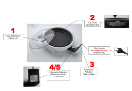
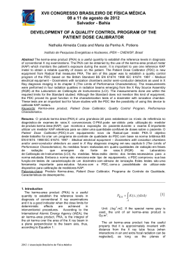
Motors | Automation | Energy | Transmission & Distribution | Coatings
TTW01
Type-Tested Assembly
www.weg.net
TTW01 - Type Tested Assembly WEG
The TTW01 modular panels comply the IEC 60439-1 and IEC 60439-3 standards.
Robust, easy to assemble and simple to size, they are designed and manufactured to allow the
assembly of TTA/PTTA (Type Tested and Partially Tested) panels by integrators properly trained by
WEG.
2
TTW01 - Type-Tested Assembly WEG
www.weg.net
Developed to meet the requirements of switchboard loads of high electrical currents and high levels of
short-circuit current, with switchgear equipment and protection that meet the requirements of quality,
safety and performance. Their modularity allows future expansions without having to make adjustments
during assembly, the modular structure is simple to install and size, allowing mounting the panels by
integrators duly trained by WEG.
Type Tested Panel WEG
(TTA and PTTA)
Safety, reliability and fast assembly.
Just like that!
Aplications
JJ
JJ
JJ
JJ
JJ
JJ
JJ
JJ
Hospitals
Banks
Shopping Centers
Buildings
Switchboards
Airports
Pumping Stations
Telecom & Data Centers
TTW01 - Type-Tested Assembly WEG
3
www.weg.net
TTW01 - Tests
According to IEC 60439-1 and IEC 60439-3 standards (which are complementary), to ensure electrical
performance and for be “TTA/PTTA”, the panel must pass by the “type tests” and “routine tests”.
The standard IEC 60439-1 addresses panels in general and IEC 60439-3 standard only applies to
panels up to 250 A with short-circuit limited up to 10 kA rms or 17 kA peak value.
The following tables list the tests required by each standard:
Type Tests
Type test according to item 8.1.1 of the IEC 60439-1 standard
Characteristics of the panels to be checked
Type test NBR IEC 60439-1:2003
Type test NBR IEC 60439-3:2004
Temperature rise limits
Yes
Yes
Dielectric properties
Yes
Yes
Short-circuit withstand current
Yes
Yes
Short-circuit withstand current of the protection circuit
Yes
Yes
Clearance and creepage distance
Yes
Yes
Mechanical operation
Yes
Yes
Protection degree
Yes
Yes
Construction and marking
Not required by this standard
Yes
Mechanical shock resistance
Not required by this standard
Yes
Rust and moist resistance
Not required by this standard
Yes
Heat resistance of the insulating material
Not required by this standard
Yes
Abnormal heat and fire resistance of the insulating material
Not required by this standard
Yes
Mechanical resistance of the enclosure fastening hardware
Not required by this standard
Yes
Routine Tests
Routine test according to item 8.1.1 of the IEC 60439-1 standard
Characteristics of panels to be checked
Conductor connections, electric operation
Insulation
Protection measurement
Insulation resistance
Certificates
4
TTW01 - Type-Tested Assembly WEG
www.weg.net
Technical Characteristics
Technical Specifications
Technical specifications
Description
TTW01-QD (enclosures)
TTW01 (columns)
TTW01-QD1A
TTW01-QD1B
TTW01-QD1C
3,150 A
250 A
250 A
250 A
65 kA rms/1s
10 kA
10 kA
10 kA
Rated insulation voltage (Ui)
1,000 V
690 V
690 V
690 V
Rated operating voltage (Ue)
690 V
690 V
690 V
690 V
Rated impulse withstand voltage (Uimp)
8 kV
6 kV (4 kV with MDW)
6 kV (4 kV with MDW)
6 kV (4 kV with MDW)
50/60 Hz
Rated current (In)
Short-circuit current (Icw)
Frequency
Access
Installation
Internal separation forms
Width (mm)
Dimensions
Height (mm)
Protection degree
50/60 Hz
50/60 Hz
50/60 Hz
Front and back
Front
Front
Front
Self-supported
Embedded and
surface-mount
Embedded and
surface-mount
Embedded and
surface-mount
1 and 2b
Not applicable
Not applicable
Not applicable
700 and 300
600
600
600
500
800
1,100
2,000 (base 100)
2,100 (base 200)
Depth (mm)
600
150
150
150
Up to IP30
-
Embedded
Embedded
Embedded
Up to IP54 1)
Ambient temperature
Altitude
Applicable standards
Self-supported
Surface-mount
Surface-mount
Surface-mount
Maximum 40 °C
Maximum 40 °C
Maximum 40 °C
Maximum 40 °C
Up to 2,000 m
Up to 2,000 m
Up to 2,000 m
Up to 2,000 m
NBR IEC 60439-1:2003
NBR IEC 60439-3:2003
NBR IEC 60439-3:2003
NBR IEC 60439-3:2003
Note: 1) For other IP values, contact WEG.
Structures and Mechanical Accessories
Self-supported panels and enclosures are manufactured in steel plates according to the following thicknesses:
Panel type
Frame (mm)
Door (mm)
Cover plate (mm)
External closing
0.9 (20 MSG)
1.5 (16 MSG)
0.9 (20 MSG)
---
Drying
TTW01 (columns)
TTW01-self-supported column
1.9 (14 MSG)
1.9 (14 MSG)
TTW01-QD (enclosures)
TTW01-QD1A and QD1B
0.9 (20 MSG)
0.9 (20 MSG)
TTW01-QD1C surface-mount
1.5 (16 MSG)
1.5 (16 MSG)
TTW01-QD1C embedded
0.9 (20 MSG)
1.5 (16 MSG)
Coating
Performed within the strictest quality standards, observing the following procedures:
1 - Plate surface treatment:
Hot alkaline
degrease
Rinse
Rinse with
refiner
Passivation
Rinse
Acid pickling
Phosphatization
Rinse
2 - After the treatment, the final painting is done with glossy, micro-textured, hybrid, 60-µm thick powder coating, according to
the table below:
Panel type
Frame
Door
Walls
Assembly sets
Finish cover plates
Self-supported
RAL 7022 (black)
RAL 7032 (gray)
RAL 7032 (gray)
Galvanized metal plate
Aluzinc metal plate
Enclosures
RAL 9003 (white)
RAL 9003 (white)
---
Galvanized metal plate
RAL 9003 (white)
Busbars
JJ The busbars are made of electrolytic copper (99.9% pure) submited to a surface treatment with 8-µm minimum thickness of
tin.
TTW01 - Type-Tested Assembly WEG
5
www.weg.net
TTW01 - Project in Part & Pieces
The TTW01 was designed to be supplied in parts and pieces divided in four main items:
1. Structure
Made within the strictest standards of profiles quality, made with steel plates and metal plate closure, are basically divided into
two product lines:
TTW01 - Columns
Available in two sizes to accommodate the functional
units and busbars.
Column with 300 mm to
accommodate the busbars.
Column with 700 mm to accommodate the
functional units and busbars.
TTW01-QD - Enclosures
Available in overlay versions or embed versions, it is a
versatile solution for various applications in power
distribution, according the requirements of
IEC 60439-3.
Surface
Overlay enclosures
Embed enclosures
2. Mounting Plates
Developed in various sizes
for installation of products
not standardized and that
do not have mounting kits
available.
6
TTW01 - Type-Tested Assembly WEG
www.weg.net
3. Mounting Kits and Accessories
Several available arrangements made in measure, for installation of circuit breakers, contactors, pushbuttons and other products.
JJ ABW fixed or removable mounted vertically - derivation bar to the right, left and TIE
JJ DWA/DWB mounted vertically or horizontal - derivation bar to the right and left
JJ Mounting kits for lighting circuits and sockets with mini circuit breakers, surge suppressors and differential switches
JJ Mounting kits for motor control and protection to assembly according to the instructions below:
JJ MPW16 + CWC7; 9; 12; 16
JJ MPW25 + CWM9; 25; 32
JJ Plate with holes for CSW pushbutton and pilot lights
Pushbutton kit
MPW + CWC/CWM kit
Circuit control kit
DWA800 kit
2xADW100 fixed kit
4. Busbar
The derivation connection system eliminates drilling in the vertical busbars, allowing total flexibility of positions in the derivation
busbars.
JJ Main busbars (vertical and horizontal) for currents up to 3,150 A provided by WEG
JJ Connections up to 250 A are made by cables placed by the painel builder
JJ Connections larger than 250 A are made by bars provided by WEG
JJ Outgoing connections are lead directly to the components terminals
Horizontal
busbar
Vertical
busbar
Vertical
busbar
Note: Connection that eliminates drilling on the main busbars.
TTW01 - Type-Tested Assembly WEG
7
www.weg.net
Registry of Type Tests in Panels
REGISTRO DOS ENSAIOS DE ROTINA EM PAINÉIS ELÉTRICOS PEP/ORDEM:
BAIXA TENSÃO (CONFORME NBR IEC 60439-1)
ALTA TENSÃO (CONFORME NBR IEC 62271-200)
Cliente:
Modelo:
Tensão (comando/força):
Grau de Proteção IP:
TAG.:
N° Série:
Corrente:
A Freq.:
Hz
PIW Aplicavel:
Plano de Pintura WAU:
Data Início:
/
/
N° de Colunas:
1. Verificações Visuais em conformidade com o projeto:
Conexões Aparafusadas
Lay-out
Componentes
Dimensional
Fiação Elétrica
Distância Isolamento
Identificações
N° Série dos Componente
2. Resistência de Isolamento: Igual ou maior que 1000 Ω por Volt de Tensão
Tensão Alimentação
Mínimo
Medido Antes
Principal:
V
MΩ
MΩ
V
Auxiliar:
MΩ
MΩ
Medido Depois
MΩ
MΩ
3. Ensaio Dielétrico: Suportar o valor da tensão aplicada durante 1 min. Sem fuga ou ruptura.
Circuito
Tensão Aplicada
Resultado
Principal
kV
Auxiliar
kV
4. Ensaio Funcional Elétrico: Operação conforme o Projeto.
Resultado:
Circuito Principal:
Circuito Auxiliar:
5. Ensaio de Pintura (Quando solicitado pelo Cliente): Espessura e Aderência conforme Projeto.
Espessura de Camada:
Especificada:
Média encontrada:
Aderência:
Especificada:
Resultado:
6. Circuito de Proteção (Aterramento):
Resultado:
7. Intertravamento, Elementos de Atuação Mecânica, Intercambiabilidade e Inserção de Componentes:
Resultado:
8. Teste Funcional Software:
Inspetor:
9. Parametrização:
Teste Funcional de Rede:
Inspetor:
Baixado
Tipo de Rede:
Manual
Não Necessita
10. Teste de Elevação de Temperatura:
11. Fechamento:
Data:
/
/
12. Materiais que acompanham o Painel:
Documentação
Sim
Não
Manuais dos Produtos
Sim
Não
Avulso
Sim
Não
Removível
Sim
Não
13. Disposição:
Inspetor WEG:
Inspetor WEG:
Inspetor Cliente:
Inspetor Cliente:
Nome Legível
Nome Legível
Liberação: Local:
Legenda:
Data:
C = Conforme NC = Não Conforme NA = Não Aplicável
Mod.0171-1/WAU
Rev.11/2010
8
Assinatura
"TRANSFORMANDO ENERGIA EM SOLUÇÕES"
TTW01 - Type-Tested Assembly WEG
Assinatura
/
/
According to the standard IEC 60439-1, the
manufacturer of Distribution Panel is the
assembler, being responsible for correct
construction and assembly of the panel,
which can be very simple and practice
following the assembly instructions from
TTW´s manual provided by WEG.
Also is an obligation of the assembler keep a
recording of results obtained during the routine tests.
WEG provides a form, as a tool, to fill fields with the
results of all tests performed on the panels by
assemblers.
Routine tests registry:
JJ Conductors connection and electrical operation
JJ Insulation
JJ Protection measurement
JJ Insulation resistance
www.weg.net
TTW01 - Safety, Reliability and Fast Assembly
Designed for fast and easy mounting can highlight the features below:
Standardized Finishings
Standard finish in gray RAL 7032 for TTW01 columns and white
RAL 9003 for TTW01-QD enclosures.
TTW01-QD
Mobile racks that allow the assembly of components out of the
enclosure. This characteristic allows the enclosure frame to go
to the customer / site, while the integrator makes the installation
of the electric components on the rack. After this task is
completed, it is just necessary to install the rack in the box that
was already sent to the site.
TW01
T
Connections above 250 A are executed by means of pre-assembled busbars, reducing the assembly time and losses of the
integrator.
TTW01 - Type-Tested Assembly WEG
9
www.weg.net
Dimensions (mm)
100
100
100
100
2000
2,000
2000
2,000
TTW01 (Columns)
200
200
300
300
560
560
600
600
600
600
560
560
600
600
600
600
550
550
700
700
700
700
300
300
TTW01-QD (Enclosures)
OpciÓn 1 - Montaje
paredsoporte
verticalpared vertical
OpciÓnsoporte
1 - Montaje
Overlay Enclosures
OpciÓn 2 - Montaje
paredsoporte
horizontal
OpciÓnsoporte
2 - Montaje
pared horizontal
BB
A
AA
B
B
A
A
B
A
Ø 9,2
C
150
150
ØØ9.2
9,2
C
Ø 9,2
Option 1 - Vertical support wall
B
B
C
C
C
Ø 9,2
Ø9.2
Option 2 - Horizontal support wall
Embed
BB
Embed enclosures
Dimentions
AA
C
C
Overlay enclosures
TTW01-QD1A TTW01-QD1B TTW01-QD1C TTW01-QD1A TTW01-QD1B TTW01-QD1C
A
560.1
860.1
1,162.7
500
800
1,100
B
660.1
660.1
662.7
600
600
600
C
500
800
1,100
-
-
-
D
600
600
600
-
-
-
Overlay enclosures
Vertical support wall
Dimentions
D
D
150
150
10
TTW01 - Type-Tested Assembly WEG
Horizontal support wall
TTW01-QD1A TTW01-QD1B TTW01-QD1C TTW01-QD1A TTW01-QD1B TTW01-QD1C
A
596
896
1,196
448
748
1,048
B
558
858
1,158
660
660
660
C
550
550
550
698
698
698
www.weg.net
MakeTTW - Sizing Software
As a complementary tool of the TTW01 design, WEG developed the MakeTTW.
The software configuration used by the customer to design the electric switchboards. The application
provides a bulletin of materials and final layout, eliminating errors and guaranteeing the TTA characteristic
required by the standard. That is possible because the Make TTW was elaborated with mechanical
definitions and pre-requirements which ensure the same characteristics as of the prototypes subject to
the type tests.
Panel preview window
Make TTW
window
Proprieties window
Projects and archives window
TTW01 - Type-Tested Assembly WEG
11
www.weg.net
Constructive Characteristics
According to item 7.7 of IEC 60439-1 that treats about the internal separation sets by partitions or
barriers (metallic or non-metallic), the typical forms of separation partitions are presented in the table
below:
Mains criteria
Sub-criteria
Without separation
Form
Form 1
Terminals for the external conductors not separated from busbars
Form 2a
Terminals for the external conductors separated from busbars
Form 2b
Terminals for external conductors not separated from busbars
Form 3a
Terminals for external conductors separated from busbars
Form 3b
Terminals for external conductors in same compartment as
associated functional unit
Form 4a
Terminals for external conductors not in same compartment as the
associated functional unit, but in individual, separate, enclosed
protected space or compartments
Form 4b
Separation of busbars from the functional units
Separation of busbars from the functional units and separation
of functional units from one to other. Separation of the terminals
for external conductors from the functional units, but not from
each other
Separation of busbars from the functional units and separation of all
functional units from one to other, including the terminals for
external conductors which are an integral part of functional unit
The internal separation form from the sets must be an agreement between the manufacturer and the end customer.
For TTW line are available the options 1 and 2B.
Form 1
Without separation.
Form 2
Separation between the distribution bars and the functional units.
Form 2b: The terminals for the
external conductors are separated
from bars.
12
TTW01 - Type-Tested Assembly WEG
www.weg.net
Technical Information - Ratings Degree or Index Protection of
Electrical Enclosures
Fulfilling the standard IEC 60529 cases and enclosures that
contain and protect electrical equipment must meet a few
degrees of protection that are designated by the letters IP
and two numeric digits, indicating protection of the
equipment to the entry of solids and liquids. The first digit
refers to the solids ingress capacity and the second digit to
the ingress capacity for fluid.
IP
0
1
2
3
Protection against ingress of solid objects (first digit)
Protection of person againt
Requirements
access to hazardous parts
with
No protection
Full penetration of 50 mm
diameter sphere not allowed.
Contact with hazardous parts
Full penetration of 12.5 mm
diameter sphere not allowed.
The jointed test finger shall have
adequate clearance from hazardous
parts
The access probe of 2.5 mm
diameter shall not penetrate
The additional letter that can optionally be part of the IP code
provides additional information about the degree of
protection of persons against access to hazardous parts.
Used only for those cases in which the protection of access
to dangerous parts is more effective than that indicated by
the first digit or when it has been replaced by X.
Identified by the codes A, B, C, D, meaning correspond
respectively to the numbers 1, 2, 3, 4, but unlike the first
numerical digit, this resource provides information about how
the frame prevents the penetration of solids, provides
50
information on accessibility of certain objects or parts of the
body into dangerous compartments of panel.50
Examples
Non-protected
Back of hand
Wire
5
Limited ingress or dust permitted
(no harmful deposit)
Wire
6
Totally protected against ingress
of dust
Wire
Table 1. Degree of protection indicated by the first characteristic digit.
Protection against harmful ingress of water (second digit)
Requirements
Protection from water
0
No protection
Non-protected
1
Protected against vertically falling
drops of water. Limited ingress
permitted
Vertically dripping
2
Protected against vertically falling
drops of water with enclosure
tilted 15º from the vertical.
Limited ingress permitted
Dripping up to 15º from the
vertical
4
A
Penetration up to 50 mm
diameter sphere
B
Test finger penetration to a
maximum of 80 mm must
not contact
C
Wire of 2.5 mm diameter x
100 mm long must not
contact hazardous
D
Wire of 1.0 mm diameter x
100 mm long must not
contact hazardous
50 Examples
50
Tool
The access probe of 1.0 mm
diameter shall not penetrate
3
Degree of protection
Finger
4
IP
IP
Table 3. Degree of protection against access to hazardous parts indicated
by the additional letter.
Examples
Protected against sprays to 60º
from vertical. Limited ingress
Limited spraying
permitted
Protected against water splashed
from all directions. Limited ingress Splashing from all directions
permitted
5
Protected against jets of water.
Limited ingress permitted
Hosing jets from all directions
6
Protected against strong jets of
water. Limited ingress permitted
Strong hosing jets from all
directions
7
Protected against the effects of
immersion between 15 cm and
1m
1 meter
1 meter
1 meter
8
Protected against long periods of
immersion under pressure
1 meter
Temporary immersion
1 meter
1 meter
1 meter
1 meter
1 meter
1 meter
1 meter
Continuous
immersion
1 meter
1 meter
1 meter
1 meter
Table 2. Degree of protection against water indicated
1 meter by the second
characteristic digit.
TTW01 - Type-Tested Assembly WEG
13
www.weg.net
Complete and Versatile Solutions
Panels with complete solutions and in measure for a wide range of automation products, with versatile
mounting plates for installation on several kind of products.
14
TTW01 - Type-Tested Assembly WEG
www.weg.net
Products
JJ Power factor correction capacitors
JJ Contactors and overload relays
JJ PFW controller and MMW multimeter
JJ Pushbuttons and pilot lights
JJ aR ang gL/gC fuses
JJ Molded-case circuit breakers up to 1,600 A
JJ Motor protective circuit breakers up to 100 A
JJ Residual current circuit breaker DRs RBW
JJ Mini circuit breakers up to 100 A
JJ
JJ
JJ
JJ
JJ
JJ
JJ
rogrammable relays, programmable logic controller (PLC),
P
human-machine interface (HMI)
Electronic relays - monitoring, timing and level relays
Smart relays SRW01
Switch disconnectors SFW and RSW
Surge suppressors SPW
Air circuit breakers up to 6,300 A
Terminal blocks BTW
TTW01
Type Tested
Panels WEG
TTW01 - Type-Tested Assembly WEG
15
WEG Worldwide Operations
WEG PINTURAS - Pulverlux
Buenos Aires
Phone: +54 11 4299 8000
[email protected]
AUSTRALIA
WEG AUSTRALIA
Victoria
Phone: +61 3 9765 4600
[email protected]
www.weg.net/au
AUSTRIA
WATT DRIVE - WEG Group
Markt Piesting - Vienna
Phone: +43 2633 404 0
[email protected]
www.wattdrive.com
BELGIUM
WEG BENELUX
Nivelles - Belgium
Phone: +32 67 88 84 20
[email protected]
www.weg.net/be
ECUADOR
WEG ECUADOR
Quito
Phone: 5144 339/342/317
[email protected]
www.weg.net/ec
MALAYSIA
WATT EURO-DRIVE - WEG Group
Shah Alam, Selangor
Phone: 603 78591626
[email protected]
www.wattdrive.com
SPAIN
WEG IBERIA
Madrid
Phone: +34 91 655 30 08
[email protected]
www.weg.net/es
FRANCE
WEG FRANCE
Saint Quentin Fallavier - Lyon
Phone: +33 4 74 99 11 35
[email protected]
www.weg.net/fr
MEXICO
WEG MEXICO
Huehuetoca
Phone: +52 55 5321 4231
[email protected]
www.weg.net/mx
SINGAPORE
WEG SINGAPORE
Singapore
Phone: +65 68589081
[email protected]
www.weg.net/sg
GERMANY
WEG GERMANY
Kerpen - North Rhine Westphalia
Phone: +49 2237 9291 0
[email protected]
www.weg.net/de
VOLTRAN - WEG Group
Tizayuca - Hidalgo
Phone: +52 77 5350 9354
www.voltran.com.mx
SCANDINAVIA
WEG SCANDINAVIA
Kungsbacka - Sweden
Phone: +46 300 73 400
[email protected]
www.weg.net/se
GHANA
ZEST ELECTRIC GHANA
WEG Group
Accra
Phone: +233 30 27 664 90
[email protected]
www.zestghana.com.gh
INDIA
WEG Electric India
Bangalore - Karnataka
Phone: +91 80 4128 2007
BRAZIL
[email protected]
WEG EQUIPAMENTOS ELÉTRICOS www.weg.net/in
Jaraguá do Sul - Santa Catarina
WEG INDUSTRIES INDIA
Phone: +55 47 3276-4002
Hosur - Tamil Nadu
[email protected]
Phone: +91 4344 301 501
www.weg.net/br
[email protected]
CHILE
www.weg.net/in
WEG CHILE
ITALY
Santiago
WEG ITALIA
Phone: +56 2 784 8900
Cinisello Balsamo - Milano
[email protected]
Phone: +39 02 6129 3535
www.weg.net/cl
[email protected]
CHINA
www.weg.net/it
WEG NANTONG
JAPAN
Nantong - Jiangsu
WEG ELECTRIC MOTORS
Phone: +86 0513 8598 9333
JAPAN
[email protected]
Yokohama City - Kanagawa
www.weg.net/cn
Phone: +81 45 550 3030
COLOMBIA
[email protected]
WEG COLOMBIA
www.weg.net/jp
Bogotá
Phone: +57 1 416 0166
[email protected]
www.weg.net/co
NETHERLANDS
WEG NETHERLANDS
Oldenzaal - Overijssel
Phone: +31 541 571 080
[email protected]
www.weg.net/nl
PERU
WEG PERU
Lima
Phone:+51 1 209 7600
[email protected]
www.weg.net/pe
PORTUGAL
WEG EURO
Maia - Porto
Phone: +351 22 9477705
[email protected]
www.weg.net/pt
RUSSIA and CIS
WEG ELECTRIC CIS
Saint Petersburg
Phone: +7 812 363 2172
[email protected]
www.weg.net/ru
SOUTH AFRICA
ZEST ELECTRIC MOTORS
WEG Group
Johannesburg
Phone: +27 11 723 6000
[email protected]
www.zest.co.za
For those countries where there is not a WEG own operation, find our local distributor at www.weg.net.
WEG Group - Automation Business Unit
Jaraguá do Sul - SC - Brazil
Phone: +55 47 3276 4000
[email protected]
www.weg.net
UK
WEG ELECTRIC MOTORS U.K.
Redditch - Worcestershire
Phone: +44 1527 513 800
[email protected]
www.weg.net/uk
UNITED ARAB EMIRATES
WEG MIDDLE EAST
Dubai
Phone: +971 4 813 0800
[email protected]
www.weg.net/ae
USA
WEG ELECTRIC
Duluth - Georgia
Phone: +1 678 249 2000
[email protected]
www.weg.net/us
ELECTRIC MACHINERY
WEG Group
Minneapolis - Minnesota
Phone: +1 612 378 8000
www.electricmachinery.com
VENEZUELA
WEG INDUSTRIAS VENEZUELA
Valencia - Carabobo
Phone: +58 241 821 0582
[email protected]
www.weg.net/ve
Cod: 50048500 | Rev: 00 | Date (m/y): 05/2014
The values shown are subject to change without prior notice.
ARGENTINA
WEG EQUIPAMIENTOS
ELECTRICOS
San Francisco - Cordoba
Phone: +54 3564 421 484
[email protected]
www.weg.net/ar
Download