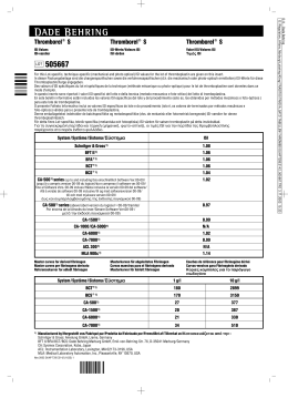
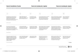
ch
sh
ais
no
ñol
guês
lands
ka
k
i
i
ar
nă
ski
e
ικά
ий
isch
sisch
3R32/3R23
Otto Bock® Modular-Kniegelenke für Exartikulation, mehrachsig ______________________4
Otto Bock® Modular Polycentric Knee Joints for Disarticulation________________________9
Articulations modulaires de genou Otto Bock® pour désarticulation, polycentrique___ 14
Articolazione di ginocchio modulare Otto Bock® per disarticolazione, pluriassiale ___ 19
Rodilla modular Otto Bock® para desarticulación, varios ejes _______________________ 24
Otto Bock® Modul-knäled för exartikulation, polycentrisk med lås ___________________ 29
Otto Bock® meerassig modulair kniescharnier voor knie-exarticulaties ______________ 33
Articulações modulares do joelho Otto Bock® para desarticulação, policêntricas ____ 38
Πολυκεντρική άρθρωση Modular για απεξάρθρωση γόνατος της Otto Bock® ________ 43
____________________________________________ 48
Printed in Germany · 647H20 – 500 – 02.05/13 – MD
647H20_neu.indd
1
11.02.2005, 11:31 Uhr
●▲
●▲
■1
18
12
16
8
14 10
▲
●
▲●9
9
▲●14 10
12a
▲● ▲●
8
3
6
17
10
11
9 ▲●
8
2
13 ▲●
11
15▲●
8
25
4
26
●7 ▲ 13 ▲●
27
29
24 23
■19
●7 ▲
10
9
▲●15
5
6
21
20
28
22
1
Einzelteile-Pack 4D9
Single-Component Pack 4D9
Kit de pièces de rechange 4D9
Imballo dei singoli componenti 4D9
Kit componentes 4D9
Onderdelenpakket 4D9
4D9 Service-Set
Conjunto de peças de reposto 4D9
Alkatrész-csomag 4D9-hez
Mindestmenge
Minimum order quantity
Quantité minimum
Quantità minima
Cantidad mínima
Minimikvantitet
Minimum aantal
Quantidade minima
Minimum mennyiség
Einzelteile
Single components
Pièces à l'unité
Singoli componenti
Componentes
Separata delar
Onderdelen
Componentes
Alkatrészek
2
647H20_neu.indd
2
11.02.2005, 11:31 Uhr
➜
●
2
4
3
5
●
1
nts
nti
3
647H20_neu.indd
3
11.02.2005, 11:31 Uhr
Deutsch
Bitte lesen Sie diese Bedienungsanleitung aufmerksam durch. Beachten Sie besonders die angeführten Sicherheitshinweise!
1 Bauteile (Abb.1)
(Die Kennzeichen der Titan-Bauteile sind in Klammern gesetzt.)
(1)
(2)
(3)
(4)
(5)
(6)
(7)
(8)
(9)
(10)
(11)
(12)
(12a)
(13)
(14)
(15)
4G70 Eingußanker
4G128 (4G107) Gelenkunterteil
4G71 (4G106) Gelenkoberteil
4G150 Achslasche
4G151 Achslasche, komplett
4G102 (4G104) Achshebel
513T4=18,8x10,2 Tellerfeder
4B86 Achsbuchse
4B82 Schlitzbuchse
507U16=⌀6,4 Kugelscheibe
501T15=M6x40 Zylinderschraube
506G3=M8x12-V Gewindestift
506G3=M8x10 Gewindestift
507S16=⌀10x1 Sicherungsring
502S19=M6 Sicherungsmutter
4Z43=H Anschlag
(16)
(17)
(18)
(19)
(20)
(21)
(22)
(23)
(24)
(25)
(26)
(27)
(28)
(29)
709S18 Steckschlüssel
501T1=M5x16 Flachrundschraube
502R1=M5x16 Zweilochmutter
4F46 Feststellung, komplett
bestehend aus:
4F47 Sperrhalter
4F48 Sperrstütze
4F18 Feststellschieber, komplett
4F49 Keil
501S41=M6x12 Senkschraube
513D15 Druckfeder
4F31 Haltelasche
501S41=M5x12 Senkschraube
21A18=⌀2x600 Perlondraht
21A12 Gewindemuffe, kurz
1.1 4D9 Einzelteile-Pack (Abb. 1, ● )
Bestehend aus 2 Anschlägen, 4 Flachrundschrauben, 4 Zweilochmuttern, 4 Schlitzbuchsen, 4
Tellerfedern, 3 Gewindestiften, 2 Sicherungsringen, 2 Sicherungsmuttern.
2 Beschreibung
2.1 Verwendungszweck und Einsatzgebiet
Die polyzentrischen Modular-Kniegelenke 3R32 (Titan) und 3R23 (Edelstahl rostfrei) mit Feststellung sind ausschließlich zur prothetischen Versorgung der unteren Extremität einzusetzen.
Einsatzgebiet nach dem Otto Bock Mobilitätssystem MOBIS®:
Empfehlung für Amputierte mit Mobilitätsgrad 1 (Innenbereichsgeher).
Zugelassen bis 125 kg Patientengewicht.
Wegen der Feststellung sind die Gelenke insbesondere für Patienten mit hohem Sicherheitsbedürfnis einzusetzen.
Bitte vermeiden Sie es, Prothesenpassteile Umgebungen auszusetzen, die Korrosionen an den Metallteilen auslösen, z.B. Süßwasser, Salzwasser, Säuren und anderen
Flüssigkeiten. Bei Einsatz des Medizinproduktes unter diesen Umgebungsbedingungen
erlöschen alle Ersatzansprüche gegen Otto Bock HealthCare.
Bitte informieren Sie Ihren Patienten.
4
647H20_neu.indd
4
11.02.2005, 11:31 Uhr
2.2 Kons
Gelenko
und Ach
verringer
Eingußa
Kupplun
Die Fes
(26) bef
zum Hin
rastet di
verlaufen
Die Fest
reihe aus
3 Aufba
Die dreid
dular-Ko
der Prot
berücksi
bei der G
Drehpun
ren von E
Prothese
Aufbauli
Achse (s
Aufbau-G
timierung
bewährt
Nach de
1G6, 1G
Aufbaua
nungsan
4 Scha
4.1 Beug
Der Eing
anschläg
geachte
sollte de
kürzeren
4.2 Lam
Perlon-T
Stumpfb
falls übe
Zur Aufn
Glasflec
überges
Deutsch
Sie be-
e
chsen, 4
mit Festetzen.
rheitsbe-
orrosioanderen
gungen
2.2 Konstruktion und Funktion
Gelenkoberteil (3) mit Kupplungskern und Gelenkunterteil (2) sind durch Achslaschen (4+5)
und Achshebel (6) miteinander verbunden. Durch die Bewegungscharakteristik der Gelenke
verringert sich in der Sitzposition die Dehnung der kosmetischen Schaumstoff-Verkleidung. Der
Eingußanker (1) wird an der Stumpfbettung befestigt und stellt die justierbare Verbindung zum
Kupplungskern her.
Die Feststellung aus Kunststoff ist zwischen den Achslaschen (4+5) mit der Haltelasche
(26) befestigt und sichert das Gelenk in Streckstellung. Zur Freigabe der Kniebeugung, z.B.
zum Hinsetzen, wird das Gelenk über den Feststellschieber (22) entriegelt. In Streckposition
rastet die Feststellung selbsttätig ein. Der Feststellzug sollte an der lateralen Prothesenseite
verlaufen.
Die Feststellung (19) läßt sich gegen den Vorbringer der Gelenke 3R21 bzw. 3R30 gleicher Baureihe auswechseln.
3 Aufbau-Empfehlungen und Montage
Die dreidimensionale Einordnung des Prothesenschaftes und der Modular-Komponenten beeinflußt die statische und dynamische Funktion
der Prothese. Die Stellung des Stumpfes muß für den Schaftanschluß Aufbaulinie
berücksichtigt werden. Lotlinien in der Frontal- und Sagittalebene, die
bei der Gipsabnahme und bei der Testschaft-Anprobe vom HüftgelenkDrehpunkt aus angezeichnet werden, erleichtern das richtige Positionieren von Eingußanker bzw. Schaftadapter.
Prothesenfuß und Kniegelenk werden nach den empfohlenen Werten zur
Aufbaulinie eingeordnet. Die Aufbaulinie läuft durch die obere, vordere
Achse (siehe Grafik). Wir empfehlen die Verwendung des Otto Bock
Aufbau-Gerätes L.A.S.A.R. Assembly 743L200 (oder des Aufbauapparates 743A100). Zur Optimierung des Aufbaus der Prothese am Patienten, hat sich das L.A.S.A.R. Posture 743L100
bewährt.
Nach den funktionellen Anforderungen des Patienten sind folgende Prothesenfüße vorgesehen:
1G6, 1G9, Normalgelenk-Fuß (1H...), SACH-Fuß (1S...), Dynamic Fuß (1D10/1D11).
Aufbauangaben und Gewichtslimitierung von Prothesenfüßen entnehmen Sie bitte der Bedienungsanleitung des jeweiligen Fußpassteiles.
4 Schaftherstellung und Befestigung des Eingußankers
4.1 Beugeanschlag
Der Eingußanker dient als Beugebegrenzung, indem er auf dem Achslager des Gelenkunterteiles
anschlägt (Abb. 2). Auf diese Anschlagfunktion muß unbedingt auch nach dem Überlaminieren
geachtet werden. Um die Anschlagfunktion zu gewährleisten und Beschädigungen zu vermeiden,
sollte der Gewindestift (12), der bei bestimmten Justierpositionen zu lang erscheint, gegen einen
kürzeren (12a) ausgetauscht werden.
4.2 Laminierung vor der Anprobe
Perlon-Trikotschlauch 623T3 in doppelter Länge des Gipsmodells zur Hälfte über das isolierte
Stumpfbett ziehen. Verbleibende Hälfte des Trikotschlauches am distalen Ende drillen und ebenfalls überziehen.
Zur Aufnahme der großen Kräfte im Bereich des Modular-Kniegelenkes wird die Armierung mit
Glasflechtschlauch 616G13 abgestuft verstärkt. Die erste Lage wird bis auf 2/3 der Schaftlänge
übergestülpt, dann abgebunden und wieder bis zur Hälfte der Schaftlänge übergestülpt.
5
647H20_neu.indd
5
11.02.2005, 11:31 Uhr
Im distalen Bereich werden 2 Lagen Carbonfasergewebe 616G12 so aufgelegt, daß der später aufzubringende Adapter 4G70 die Carbonfaser als ringsherum 3 cm überstehende Unterlage hat.
Zwei Lagen Perlon-Trikotschlauch 623T3 überziehen.
Das Laminieren erfolgt im Doppelgußverfahren, d. h. der erste Guß wird bis 2/3-Länge mit Orthocryl-Laminierharz 617H19 gegossen. Der proximale Schaftanteil wird im nachfolgenden Guß mit
Orthocryl® weich 617H17 laminiert.
Nach dem Aushärten des ersten Gusses wird vor Laminierung des proximalen Schaftanteils mit
Orthocryl® weich 617H17 erneut 2 Lagen Perlon-Trikotschlauch 623T3 übergezogen.
4.3 Anbringen des Eingußankers
Den korrekt angepaßten Eingußanker vor der Verklebung mit der Stumpfbettung präparieren.
Dazu die Kupplungsöffnung mit Plastaband 636K8 ausfüllen (Abb. 3) .
Stumpfbettung und Gelenk in den Aufbau-Apparat einspannen. Spachtelmasse aus Orthocryl®Siegelharz 617H21 und Talkum 639A1 anmischen, und Eingußanker ankleben. Zur Anprobe mit
Klebeband 627B2 sichern.
6 Justie
Das Mod
Die Fest
sich an d
Schraub
Schraub
Nach de
verlässig
Bei jede
ausgeta
die Ansc
derung v
7 Scha
Für die G
4.4 Fertigstellen des Schaftes
Nach der Anprobe den Eingußanker zusätzlich mit Flachrundschrauben (17) und Zweilochmuttern (18) mit der Stumpfbettung verschrauben und danach überlaminieren.
Weitere Armierung wie folgt:
Über den gesamten Schaft wird nun eine Lage Perlon-Trikotschlauch 623T3 gezogen und oben
ringfögmig abgebunden, damit nach dem Aufbringen von 2 Lagen Carbonfasergewebe 616G12
über den Armen des Adapters 4G70 die zweite Lage Perlon-Trikotschlauch 623T3 das Carbonfasergewebe als Zwischenschicht hat.
Jetzt wird noch einmal mit Glasgeflechtschlauch 616G13 (wie unter 4.2 beschrieben) abgestuft
verstärkt.
Zuletzt 2 Lagen Perlon-Trikotschlauch 623T3 überziehen.
Das Laminieren erfolgt ebenfalls wie beim ersten Guß.
Die Justierschrauben (12/12a) nach der Montage mit dem Drehmomentschlüssel 710D1 festziehen. Anzugsmoment: 15 Nm.
Die Gewindestifte bei der Fertigstellung der Prothese mit Loctite 636K13 sichern.
5 Einstellen der Lagerung
Die in Buchsen gelagerten Achszapfen der Achshebel sind mit dem Gelenkoberteil und -unterteil
gelenkig verbunden. Die Art der Lagerung und Verschraubung erlaubt es, die Friktion zu erhöhen
oder zu vermindern und verschleißbedingtes Spiel nachzujustieren. Dazu Sicherungsmutter (14)
mit beigelegtem Steckschlüssel 709S18 (16) fixieren, und Zylinderschraube (11) mit 5-mm-Stiftschlüssel anziehen (Abb. 4).
Die spielfreie Einstellung muß in jedem Fall nach einer Einlaufzeit von 2 bis 4 Wochen erfolgen.
Bei jeder Wartungsarbeit sollen die Einstellung kontrolliert und die Anschläge 4Z43=H ausgetauscht werden.
Zur Schmierung der Achsbuchsen (8) und Schlitzbuchsen (9) Otto Bock Spezial-Schmiermittel
633G6 verwenden.
6
647H20_neu.indd
6
11.02.2005, 11:31 Uhr
8 Wartu
Otto Bo
Einstellu
Bitte kon
Funktion
ist dabei
Die volls
päter aufhat.
it OrthoGuß mit
nteils mit
parieren.
thocryl®robe mit
6 Justieren der Feststellung (Abb. 5)
Das Modular-Kniegelenk 3R23 bzw. 3R32 ist werkseitig kontrolliert und einbaufertig eingestellt.
Die Feststellung des Gelenkes rastet bei der Streckung selbsttätig leicht und hörbar ein. Sie läßt
sich an der Senkschraube mit Innensechskant (24) über den Messingkeil (23) nachstellen.
Schraube nach rechts drehen = schwerer zu entriegeln, weniger Spiel, rastet schwerer ein.
Schraube nach links drehen = leichter zu entriegeln, mehr Spiel, rastet leichter ein.
Nach der Justierung ist sicherzustellen, dass die Feststellung einrastet und das Gelenk zuverlässig verriegelt ist. Justierschraube (24) mit Loctite 636K13 sichern.
Bei jeder Wartungsarbeit sollen die Feststellung kontrolliert und die Anschläge 4Z43=H (15)
ausgetauscht werden. Sollte die Feststellung anschließend nicht sicher einrasten, müssen
die Anschläge nachgearbeitet werden. An den Kunststoffteilen der Feststellung keine Veränderung vornehmen.
7 Schaumkosmetik
Für die Gelenke 3R23/3R32 den Schaumstoff-Überzug 6R6 (3R6, 3S106) verwenden.
Achtung
Verwenden Sie kein Talkum zur Beseitigung von Geräuschen in der Schaumkosmetik.
Talkum entzieht den mechanischen Bauteilen das Fett. Dieses verursacht erhebliche
Funktionsstörungen der Mechanik und kann zum Blockieren des Kniegelenkes und
damit zum Sturz des Patienten führen. Bei Einsatz des Medizinproduktes unter Verwendung von Talkum erlöschen alle Ersatzansprüche.
lochmut-
nd oben
616G12
Carbon-
bgestuft
0D1 fes-
Hinweis
Zur Optimierung der Gleiteigenschaften und zur Beseitigung von Geräuschen bitte das
Silikonspray 519L5 direkt auf die Reibflächen in der Schaumkosmetik sprühen.
8 Wartungshinweise
Otto Bock empfiehlt, nach individueller Eingewöhnungszeit des Patienten an die Prothese, die
Einstellungen des Kniegelenkes erneut an die Patientenanforderungen anzupassen.
Bitte kontrollieren Sie das Kniegelenk mindestens einmal jährlich auf Verschleißzustand und
Funktionalität und nehmen Sie gegebenenfalls Nachjustierungen vor. Besonderes Augenmerk
ist dabei auf den Bewegungswiderstand und auf ungewöhnliche Geräuschentwicklung zu legen.
Die vollständige Beugung und Streckung muss gewährleistet sein.
Achtung - Bitte informieren Sie Ihren Patienten!
Je nach Umgebungs- und Einsatzbedingungen kann die Funktion des Kniegelenkes beeinträchtigt werden. Um eine Gefährdung des Patienten zu vermeiden, darf das Kniegelenk nach spürbaren Funktionsveränderungen nicht weiter benutzt werden. Diese spürbaren Funktionsveränderungen können sich z.B. als Schwergängigkeit, unvollständige
Streckung, nachlassende Schwungphasensteuerung bzw. Standphasensicherheit,
Geräuschentwicklung, etc. bemerkbar machen.
-unterteil
erhöhen
utter (14)
mm-Stift-
erfolgen.
H ausge-
Maßnahme
Aufsuchen einer Fachwerkstatt zur Überprüfung der Prothese.
miermittel
7
647H20_neu.indd
7
11.02.2005, 11:31 Uhr
9 Gewährleistung
Eine Gewährleistung kann nur gewährt werden, wenn das Produkt unter den vorgegebenen
Bedingungen und zu den vorgesehenen Zwecken eingesetzt wird. Dieses Produkt wird nach
ISO-Bedingungen geprüft. Otto Bock übernimmt eine Gewährleistung von 2 Jahren, wenn ausschließlich Modular-Bauteile entsprechend des Otto Bock MOBIS® eingesetzt werden (siehe
Gewährleistungsbedingungen).
8 Konformitätserklärung
Otto Bock erklärt als Hersteller in alleiniger Verwantwortung, daß die polyzentrischen ModularKniegelenke 3R32 und 3R23 mit Feststellung mit den Anforderungen der Richtlinie 93/42/EWG
übereinstimmen.
1 Comp
(Titanium
(1)
(2)
(3)
(4)
(5)
(6)
(7)
(8)
(9)
(10)
(11)
(12)
(12a)
(13)
(14)
(15)
1.1 4D9
Consists
spring w
2 Desc
2.1 Appl
The Mod
be exclu
Field of a
Due to t
degree o
8
647H20_neu.indd
8
11.02.2005, 11:31 Uhr
gebenen
ird nach
enn ausn (siehe
Modular42/EWG
English
Please read the instructions carefully. Pay special attention to the cited safety information!
1 Components (fig.1)
(Titanium Parts are placed in brackets)
(1)
(2)
(3)
(4)
(5)
(6)
(7)
(8)
(9)
(10)
(11)
(12)
(12a)
(13)
(14)
(15)
4G70 Lamination Anchor
4G128 (4G107) Lower Joint Section
4G71 (4G106) Upper Joint Section
4G150 Posterior Linkage Bar
4G151 Posterior Linkage Bar, complete
4G102 (4G104) Anterior Linkage Bar
513T4=18,8x10,2 Belleville Spring
Washer
4B86 Knee Axis Bushing
4B82 Slotted Bushing
507U16=⌀6,4 Ball Washer
501T15=M6x40 Cap Screw
506G3=M8x12-V Set Screw
506G3=M8x10 Set Screw
507S16=⌀10x1 Lock Ring
502S19=M6 Lock Nut
4Z43=H Knee Stop
(16)
(17)
(18)
(19)
(20)
(21)
(22)
(23)
(24)
(25)
(26)
(27)
(28)
(29)
709S18 Socket Wrench
501T1=M5x16 Truss Head Screw
502R1=M5x16 Round Nut
4F46 Lock, complete
consisting of:
4F47 Lock Holder
4F48 Lock Support
4F18 Lock Handle, complete
4F49 Wedge
501S41=M6x12 Countersunk Head
Screw
513D15 Compression Spring
4F31 Retainer Bracket
501S41=M5x12 Countersunk Head
Screw
21A18=⌀2x600 Perlon Cord
21A12 Threaded Sleeve, short
1.1 4D9 Single-Component Pack (fig. 1, ● )
Consists of 2 knee stops, 4 truss head screws, 4 round nuts, 4 slotted bushings, 4 Belleville
spring washers, 3 set screws, 2 lock rings, 2 lock nuts.
2 Description
2.1 Application and recommendations
The Modular Polycentric Knee Joints with lock 3R32 (titanium) and 3R23 (stainless steel) are to
be exclusively used for the prosthetic fitting of amputations of the lower limb.
Field of application according to the Otto Bock Mobility System MOBIS®:
Recommendation for amputees with mobility grade 1 (indoor walkers).
Approved for a patient weight of up to 125 kg.
Due to the lock, the knee joints are especially recommended for patients, who require a high
degree of stability.
The Otto Bock MOBIS® is not intended to be used as a guide to obtaining reimbursement for prosthetic components in the USA.
9
647H20_neu.indd
9
11.02.2005, 11:31 Uhr
Please avoid exposing prosthetic components to surroundings that corrode metal parts,
for example, freshwater, saltwater, acids and other liquids. Using this medical product
in such environmental conditions will render all claims against Otto Bock HealthCare
null and void.
Please inform your patients.
2.2 Construction and Function
The upper joint section (3) with coupling core and the lower joint section (2) are connected by
posterior (4+5) and anterior (6) linkage bars. Due to the motion characteristics of the joints, stretching of the cosmetic foam cover has been reduced in the seated position. The lamination anchor
(1) is attached to the socket and performs the adjustable connection to the coupling core.
The lock of plastic is attached to the retainer bracket (26) between the posterior linkage bars
(4+5), thus securing the joint in extended position. To provide knee flexion, e.g. when sitting down,
the joint is released via the lock handle (22). In extended position the lock automatically engages.
The perlon cord should run on the lateral side of the prosthesis.
The lock (19) may be replaced by the extension assist of the 3R21 or 3R30 Knee Joints (same
line of production).
3 Alignment Recommendations and Assembly
The three-dimensional arrangement of the prosthetic socket and modular elements affects the prosthesis' static and dynamic functions. The
position of the residual limb must be taken into account for the connecReference
line
tion to the socket. Plumb lines in the frontal and sagittal planes from the
hip joint's center of rotation marked during plaster cast taking and trial
fitting of the test socket will facilitate correct positioning of lamination
anchor or socket adapter.
The prosthetic foot and knee joint are aligned according to the recommended values. The reference line runs through the middle of the anterior, upper axis (see graphic).
We recommend using the Otto Bock device for alignment L.A.S.A.R. Assembly 743L200 (or the
configuration appliance 743A100). The L.A.S.A.R. posture 743L100 has succeeded in optimizing the alignment of the prosthesis for the patient.
Depending on the patient's functional demands, the following prosthetic feet can be used:
1G6, 1G9, Single Axis Foot (1H...), SACH-Foot (1S...), Dynamic Foot (1D10/1D11).
For alignment specifications and weight limits of prosthetic feet, please use the operational instructions for the respective foot set-up.
4 Socket Fabrication and Lamination Anchor Attachment
4.1 Flexion Stop
The Lamination anchor serves as flexion stop, as it is placed on the axis bearing of the lower joint
section (fig. 2). Attention must be paid to this stop function, also after lamination.
In order to ensure proper flexion stop function and to avoid any damage, the set screw (12), which
seems to be too long in certain adjustment positions, shoud be replaced by a shorter one (12a).
10
647H20_neu.indd
10
11.02.2005, 11:31 Uhr
4.2 Lam
Take the
del and p
pull it ov
The 616
forces in
turn it up
Put 2 lay
cumfere
Pull over
The twowith 617
with 617
Upon ha
laminatio
4.3 Putt
Correctl
purpose
Clamp th
cryl® Sea
adhesive
4.4 Sock
After tria
socket a
Then pro
Pull one
larly so t
layer of c
4G70 Ad
Now the
bed in 4
Finally, p
Proceed
Upon co
Wrench
Secure
636K13
5 Adjus
The axis
per and
of the fri
(14) usin
wrench (
al parts,
product
lthCare
ected by
ts, stretn anchor
re.
age bars
ng down,
ngages.
s (same
0 (or the
n optimi-
ed:
tional in-
wer joint
2), which
ne (12a).
4.2 Lamination Prior to Trial Fitting
Take the Perlon Stockinette 623T3 in length corresponding to twice the length of the plaster model and pull it over the isolated socket. Twist the other half of the stockinette on the distal end and
pull it over the socket as well.
The 616G13 Fibreglass Stockinette lamination is to be gradually reinforced so as to absorb large
forces in the modular knee joint. Turn up the first layer to 2/3 of the socket length, tie it and then
turn it up again to the half of the socket length.
Put 2 layers of 616G12 Carbon-Fiber Cloth on the distal area with 3-cm overlap around the circumference so as to provide underlying pad to the 4G70 Adapters to be mounted later on.
Pull over two layers of the 623T3 Perlon Stockinette.
The two-stage method is used for socket lamination in that the socket is cast up to 2/3 of length
with 617H19 Orthocryl Lamination Resin first. Then the proximal part of the socket is laminated
with 617H17 Orthocryl® Flexible Resin.
Upon hardening of the first cast, pull over again 2 layers of the 623T3 Perlon Stockinette prior to
lamination of the proximal part of the socket with 617H17 Orthocryl® Flexible Resin.
4.3 Putting on Lamination Anchor
Correctly adapted lamination anchor is to be prepared before gluing with the socket. For that
purpose fill the coupling opening with 636K8 Plastaband (fig. 3).
Clamp the socket and knee joint into the alignment apparatus. Mix the putty from 617H21 Orthocryl® Sealing Resin and 639A1 Talcum Powder, and glue on the lamination anchor. Secure with
adhesive tape 627B2 for trial fitting.
4.4 Socket Completion
After trial fitting, screw the lamination anchor with cap screws (17) and round nuts (18) with
socket and then cast with laminate.
Then proceed with lamination as follows:
Pull one layer of the 623T3 Perlon Stockinette over the whole socket and tie it on the top circularly so that the second layer of 623T3 Perlon Stockinette can be provided with an intermediate
layer of carbon-fiber cloth after the two layers of 616G12 Carbon-Fiber Cloth are placed on the
4G70 Adapter Arms.
Now the socket is to be gradually reinforced with the 616G13 Fiberglass Stockinette (as decribed in 4.2).
Finally, pull over 2 layers of the 623T3 Perlon Stockinette.
Proceed with lamination in the same way as during the first cast.
Upon completion ot the assembly tighten the adjustment screws (12/12a) with Torque
Wrench 710D1. Torque: 15 Nm (11 ft. lbs./133 lbs. in.).
Secure the adjustment screws in their final adjustment position of the prosthesis using
636K13 Loctite.
5 Adjustment of the Bearing
The axis pins of the linkage bars are mounted in bushings and are hingedly connected to the upper and lower joint sections. This type of bearing and assembly allows increasing or decreasing
of the friction as well as readjustment of tolerance variation due to wear. To this end fix lock nut
(14) using enclosed 709S18 Socket Wrench (16) and tighten cap screw (11) with 5 mm Allen
wrench (fig. 4).
11
647H20_neu.indd
11
11.02.2005, 11:31 Uhr
Adjustments must be made to eliminate excessive clearance following 2 to 4 weeks of use. Please
also monitor this adjustment during routine maintenance of the knee and replace the 4Z43=H
Knee Stops as necessary (15).
For lubrication of the axis bushings (8) and slotted bushings (9) use 633G6 Otto Bock Special
Lubricant.
6 Adjustment of the Lock (fig. 5)
The 3R23 and 3R32 Modular Knee Joints have been factory set “for immediate use”. The lock
of the joint automatically engages in an audible manner when extension takes place. It can be
readjusted by means of the countersunk head screw (24) via brass wedge (23).
Turn screw clockwise:
disengaging becomes more difficult, less play, engaging becomes more difficult.
Turn screw counterclockwise:
disengaging becomes easier, more play, engaging becomes easier.
After adjustment it is to ensure, that the lock engages and that the joint is reliably locked.
Secure the adjustment screw (24) using 636K13 Loctite.
Whenever maintenance work is performed, the lock should be checked and the 4Z43=H
Knee Stops (15) be replaced. If afterwards the lock does not securely catch, the stops must
be reworked. Do not modify the plastic parts of the lock.
7 Foam cosmetic cover
Use foam cover 6R6 (3R6, 3S106) for joints 3R32/3R23.
Attention
To eliminate noise in the cosmetic foam cover, use 519L5 Silicone Spray. Do not use
talcum powder! Talcum powder reduces the lubrication of the mechanical parts, which
may lead to a malfunction and thus increase the risk of failure. Using this medical
product after application of talcum powder will render all claims against Otto Bock
HealthCare null and void.
Useful information
To optimize sliding and for eliminating noises, please apply 519L5 Silicone Spray directly on the friction surfaces of the foam cosmetic covers.
8 Maintenance information
Otto Bock recommends the readjustment of the knee joint’s settings after the patient has spent
a period of time getting used to the prosthesis. This period of time varies depending on individual
patient characteristics.
Please check the wear and functionality of the knee joint at least once a year and make follow-up
adjustments if need be. Pay special attention to resistance to movement and the development of
unusual sounds. Complete flexion and extension must be guaranteed.
12
647H20_neu.indd
12
11.02.2005, 11:31 Uhr
9 Warra
The Otto
tions and
has been
if exclusi
ase refe
10 Dec
Otto Boc
Joints wi
e. Please
4Z43=H
Attention! Please inform your patients.
Due to different environmental conditions and conditions of application, the function of
the knee joint can be impaired. To avoid the risk of accident and possible injury to the
patient, the knee joint must no longer be used after a noticeable loss of function has
occurred. This noticeable loss of function can be for example stiffness, non-attainment
of the extension stop, decreasing swing phase or stance phase stability, abnormal
noises, etc.
Special
The lock
t can be
Measure
Have the knee joint examined by a specialist workshop where service parts or, if
necessary, the entire knee joint will be exchanged.
9 Warranty
locked.
4Z43=H
ps must
The Otto Bock Warranty applies only when the product is used according to the specified conditions and for the intended purposes, following all manufacturer’s recommendations. This product
has been tested according to ISO recommendations. Otto Bock will offer a warranty of 2 years,
if exclusively Modular Components have been installed according to the Otto Bock MOBIS® (please refer to the Terms of Warranty).
10 Declaration of Conformity
Otto Bock as manufacturer with sole responsibility declares that the Modular Polycentric Knee
Joints with lock 3R32 and 3R23 conform to the requirements of 93/42 EEC Guideline.
not use
, which
medical
o Bock
y direct-
as spent
ndividual
ollow-up
pment of
13
647H20_neu.indd
13
11.02.2005, 11:31 Uhr
Français
Veuillez lire attentivement le présent mode d’emploi et observer en particulier les
consignes de sécurité.
1 Eléments de construction (ill.1)
(Les références des pièces en titane se trouvent entre parenthèses).
(1) 4G70 Ancre à couler
(15) 4Z43=H Butée
(2) 4G128 (4G107) Partie inférieure de
(16) 709S18 Clé à douille
l’articulation
(17) 501T1=M5x16 Boulon à tête bombée
(3) 4G71 (4G106) Partie superieure de
(18) 502R1=M5x16 Ecrou à 2 trous frontaux
l’articulation
(19) 4F46 Système de verrouillage, complet
(4) 4G150 Languette axiale
se compose de :
(5) 4G151 Languette axiale complète
(20) 4F47 Support de blocage
(6) 4G102 (4G104) Levier axial
(21) 4F48 Soutien de blocage
(7) 513T4=18,8x10,2 Ressort à disques
(22) 4F18 Poussoir d’arrêt complet
(8) 4B86 Douille axiale
(23) 4F49 Coin
(9) 4B82 Douille fendue
(24) 501S41=M6x12 Vis
(10) 507U16=⌀ 6,4 Rondelle à portée
(25) 513D15 Ressort de pression
sphérique
(26) 4F31 Languette de blocage
(11) 501T15=M6x40 Vis à tête cylindrique
(27) 501S41=M5x12 Vis
(12) 506G3=M8x12-V Tige filetée
(28) 21A18=⌀2x600 Câble en perlon
(12a) 506G3=M8x10 Tige filetée
(29) 21A12 Manchon taraudé court
(13) 507S16=⌀10x1 Disque de sûreté
(14) 502S19=M6 Contre-écrou
1.1 4D9 Kit de pièces détachées (ill. 1, ●)
Composé de 2 butées, 4 boulons à tête bombée, 4 écrous à 2 trous frontaux, 4 douilles fendues,
4 ressorts à disque, 3 tiges filetées, 2 disques de sûreté, 2 contre-écrous.
2 Description
2.1 Destination et recommandation
Les articulations de genou polycentriques 3R32 (titane) et 3R23 (acier inoxydable) avec verrou
sont destinées exclusivement pour l’appareillage orthopédique des membres inférieurs.
Champs d’application selon le système de mobilité Otto Bock MOBIS®:
Recommandé pour des personnes amputées avec degré de mobilité 1 (marcheurs en intérieur)
Admis jusqu‘à 125 kg - poids du patients.
Cette articulation à verrou convient surtout aux patients recherchant une haute sécurité.
Evitez d’exposer les pièces détachées de la prothèse à un environnement pouvant
entraîner une corrosion des parties métalliques (eau douce, eau salée, acides et autres
liquides. L’emploi de l’appareil médical dans de telles conditions ambiantes fait perdre
tout droit à indemnité envers la société Otto Bock HealthCare.
Veuillez informer votre patient.
14
647H20_neu.indd
14
11.02.2005, 11:31 Uhr
2.2 Con
La partie
l’articula
caractèr
esthétiqu
raccorde
Le systè
languette
sera déb
Le câble
Le systè
3R21 ou
3 Align
La dispo
modulair
La posit
l'emboîtu
ture d'es
de l’artic
sagittal
l’adapta
La dispo
port à la
A ligne d
Nous re
743L200
sur le pa
Selon le
suivants
1G6, 1G
L’assem
correspo
4 Réali
4.1 Buté
L’ancre à
inférieure
après la
ons, il co
trop long
4.2 Stra
Enfiler le
de l‘emb
et ensuit
Français
lier les
mbée
ontaux
omplet
2.2 Construction et fonctionnement
La partie supérieur de l’articulation (3) avec le noyau d’accouplement et la partie inférieure de
l’articulation (2) sont reliées entre-elles par les languettes axiales (4+5) et le levier axial (6). Le
caractère du mouvement de l’articulation réduit, en position assise, l’extension du revêtement
esthétique en mousse. L’ancre à couler (1) sera fixée à l’emboîture du moignon et formera le
raccordement ajustable au noyau d’accouplement.
Le système de verrouillage en matière plastique est fixé entre les languettes axiales (4+5) et la
languette de blocage (26). Pour libérer la flexion du genou, p. ex. pour s’asseoir, l’articulation
sera débloquée par le poussoir d’arrêt (22). En extension, le verrou se bloque automatiquement.
Le câble de traction doit être placé sur la face latérale de la prothèse.
Le système de verrouillage (19) se laisse échanger contre le rappel d’extension des articulations
3R21 ou 3R30 de la même série de construction.
3 Alignement
fendues,
c verrou
.
1 (mar-
.
pouvant
t autres
perdre
La disposition tridimensionnelle de la tige de la prothèse et des éléments
modulaires influence la fonction statique et dynamique de la prothèse.
La position du moignon doit être prise en compte pour le raccord de
Ligne de
montage
l'emboîture. Lors du démoulage du plâtre et de l’essayage de l'emboîture d'essai, il est recommandé de tracer à partir du point de rotation
de l’articulation de la hanche des lignes verticales dans l’axe frontal et
sagittal afin de faciliter le positionnement de l’ancre à couler et/ou de
l’adaptateur de l'emboîture.
La disposition du pied prothétique et de l’articulation de genou par rapport à la ligne d’assemblage est conforme aux valeurs recommandées.
A ligne de montage passe par le milieu de l’axe supérieur avant (voir graphique).
Nous recommandons d’utiliser l’appareil d’assemblage Otto Bock L.A.S.A.R. Assembly
743L200 (ou l’appareil d’assemblage 743A100). Pour optimiser l’assemblage de la prothèse
sur le patient, le L.A.S.A.R. Posture 743L100 a fait ses preuves.
Selon les exigences fonctionnelles des patients, les combinaisons avec les pieds prothétiques
suivants sont indiquées:
1G6, 1G9, Pied articulé (1H...), Pied SACH (1S...), Pied Dynamic (1D10/1D11).
L’assemblage du pied prothétique est indiqué dans le mode d’emploi de l’élément prothétique
correspondant.
4 Réalisation de l‘emboîture et fixation de l‘ancre à couler
4.1 Butée de la flexion
L’ancre à couler a pour fonction de limiter la flexion en venant buter sur le palier axial de la partie
inférieure de l’articulation (ill. 2). Il faut toujours tenir compte de cette fonction de butée, même
après la stratification. Pour garantir la fonction de la butée et prévenir d‘éventuelles déteriorations, il convient de remplacer par une tige filetée plus courte (12) la tige filetée qui peut s‘avérer
trop longue lors de certaines positions de réglage.
4.2 Stratification avant l‘essayage
Enfiler le tricot tubulaire en perlon 623T3 en double longueur du positif plâtré jusqu‘à mi-longueur
de l‘emboîture isolée. Enrouler la moitié restante du tricot tubulaire autour de l‘extrémité distale
et ensuite recouvrir.
15
647H20_neu.indd
15
11.02.2005, 11:31 Uhr
Pour amortir les pressions dans la zone des articulations de genou modulaires, le renforcement
se fera progressivement à l‘aide d‘une couche de tissu en fibre de verre 616G13. Enfiler la
première couche jusqu‘au 2/3 de la longueur de l‘emboîture, ensuite nouer et enfiler de nouveau
jusqu‘à mi-longueur de l‘emboîture.
A l‘extrémité distale, mettre deux couches de tissu en fibre de carbone 616G12. Procéder de
manière à avoir un surplus de fibre de carbone d‘environ 3 cm qui servira plus tard à placer
l‘adaptateur 4G70.
Recouvrir d‘une double couche de tricot tubulaire en perlon 623T3.
La stratification s‘effectue selon le procédé de la double lamination, c‘est-à-dire laminer la première
coulée jusqu‘au 2/3 de sa longueur avec de la résine Orthocryl 617H19. Le segment proximal de
l‘emboîture sera stratifié au cours de la coulée suivante à l‘aide de l‘Orthocryl® souple 617H17.
A l‘issue du durcissement de la première coulée, recouvrir de nouveau d‘une double couche de
tricot tubulaire en perlon 623T3 avant la stratification du segment proximal de l‘emboîture avec
l‘Orthocryl® souple 617H17.
4.3 Mise en place de l‘ancre à couler
Préparer l‘ancre à couler adéquate avant de la coller à l‘emboîture. A cet effet, combler l‘orifice
de fixation avec du ruban adhésif 636K8 (ill. 3).
Installer l‘emboîture et l‘articulation dans l‘appareil de montage. Mélanger le mastic en résine
d‘Orthocryl® 617H21 avec du talc 639A1, et coller à l‘ancre à couler. Pour l‘essayage, assurer
la fixation à l‘aide d‘une bande autocollante 627B2.
4.4 Finition de l‘emboîture
Après l‘essayage, visser accessoirement l‘ancre à couler avec des boulons à tête bombée (17)
et des écrous à deux trous (18). Ensuite consolider.
Pour d‘autres renforcements, procéder comme suit :
A présent, recouvrir l‘ensemble de l‘emboîture d‘une couche de tricot tubulaire en perlon 623T3
et ligaturer en forme d‘anneau sur la partie supérieure. Ce qui va permettre au tissu de fibre
de verre de servir de couche tampon à la deuxième couche de tricot tubulaire 623T3 après
l‘application d‘une double couche de tissu en fibre de verre 616G12 par-dessus les branches
de l‘adaptateur 4G70.
Une fois encore, renforcer progressivement avec de la fibre de verre 616G13 (voir description
faite dans le paragraphe 4.2).
Pour finir, recouvrir d‘une double couche de tricot tubulaire en perlon 623T3.
La stratification s‘effectue également comme lors du premier coulage.
Après le montage, resserrer complètement les écrous de réglage (12/12a) à l‘aide de la clé
dynamométrique 710D1. Couple de serrage : 15 Nm.
Pour plus de sécurité, enduire les tiges filetées de loctite 636K13 lors de la finition de la prothèse.
5 Réglage du logement des paliers
Les tourillons du levier axial logés dans des coussinets forment un raccordement articulé entre
la partie inférieure et la partie supérieure de l’articulation. Le type de logement des paliers et le
vissage autorisent l’augmentation ou la réduction de la friction, ainsi qu’un ajustage ultérieur du
jeu dû à l’usure. Pour cela, fixer le contre-écrou (14) avec la clé à douille 709S18 (16) jointe et
serrer la vis à tête cylindrique (11) avec une clé mâle de 5 mm (ill. 4).
Un réglage du jeu devra avoir lieu dans les deux à quatre semaines suviant la mise en service de
l’articulation. A chaque entretien, contrôler l’ajustage et échanger les butées 4Z43=H (15).
16
647H20_neu.indd
16
11.02.2005, 11:31 Uhr
Utiliser la
fendues
6 Ajust
Les artic
montage
Le systè
laiton (23
Tourner
Tourner
Après l’e
rouillée.
A chaqu
Si le ver
sur les b
7 Revê
Pour les
8 Entre
Otto Boc
tient apr
Veuillez c
genou et
doit être
et l’exten
rcement
Enfiler la
nouveau
Utiliser la graisse spéciale Otto Bock 633G6 pour graisser les douilles axiales (8) et les douilles
fendues (9).
céder de
à placer
Les articulations modulaires de genou 3R23 et 3R32 sont contrôlées en usine et livrées prêtes au
montage. Le blocage automatique du système de verrouillage à l’extension est léger et audible.
Le système de verrouillage peut être ajusté en réglant la vis à 6 pans creux (24) sur la pièce en
laiton (23).
Tourner la vis vers la droite = déverrouillage plus dur, moins de jeu, blocage moins facile.
Tourner la vis vers la gauche = déverrouillage moins dur, plus de jeu, blocage plus facile.
Après l’essayage, assurez-vous que le verrou soit bloqué et que l’articulation soit bien verrouillée. Fixez la vis d’ajustage (24) à la Loctite.
A chaque entretien, contrôlez le système de verrouillage et échangez les butéess 4Z43=H (15).
Si le verrou ne se bloque pas et que l’articulation ne se verrouille pas correctement, intervenez
sur les butées. Ne procédez à aucune modification sur les parties plastiques du verrou.
première
ximal de
H17.
ouche de
ure avec
r l‘orifice
n résine
assurer
6 Ajustage du système de verrouillage (ill. 5)
7 Revêtement esthétique en mousse
Pour les articulations 3R32/3R23, utiliser le revêtement en mousse 6R6 (3R6, 3S106).
Attention
Ne pas utiliser de talc pour éliminer les bruits de la mousse cosmétique. Le talc assèche
les éléments de construction mécaniques, ce qui entraîne des dysfonctionnements considérables de la partie mécanique et peut provoquer un blocage de l’articulation de
genou et donc faire chuter le patient. L’emploi de talc sur l’appareil médical fait perdre
tout droit à indemnité.
bée (17)
Remarque
Pour optimiser les capacités de glissage et pour éliminer des bruits, il est possible
d’utiliser un spray de silicone (519L5) à pulvériser directement sur la surface de frottement de la mousse cosmétique.
n 623T3
de fibre
T3 après
branches
scription
de la clé
8 Entretien
Otto Bock recommande d’adapter les réglages de l’articulation de genou aux exigences du patient après la période d’adaptation individuelle.
Veuillez contrôler au moins une fois par an l’état d’usure et la fonctionnalité de l’articulation de
genou et, le cas échéant, effectuer les réajustements nécessaires. Une attention toute particulière
doit être accordée à la résistance de mouvement et à l’émission de bruits inhabituels. La flexion
et l’extension doivent être complètes.
othèse.
ulé entre
iers et le
érieur du
jointe et
ervice de
15).
17
647H20_neu.indd
17
11.02.2005, 11:31 Uhr
Attention! Veuillez informer votre patient.
Certaines conditions ambiantes et d’utilisation peuvent nuire au bon fonctionnement
de l’articulation de genou. Afin de ne pas mettre en danger le patient, l’articulation
de genou ne doit plus être utilisée dès que des modifications dans le fonctionnement
sont perceptibles. Ces changements peuvent se traduire par exemple par une certaine
dureté, une extension incomplète, une réduction du contrôle de la phase pendulaire
et/ou de la sécurisation de la phase d’appui, l’émission de bruits, etc.
Mesures à prendre
Contacter un atelier spécialisé pour faire contrôler et, le cas échéant, remplacer
l’articulation de genou.
9 Garantie
Le produit n’est couvert par la garantie que s’il est utilisé dans les conditions précitées et aux fins
prévues. Ce produit a été testé selon les recommandations des normes ISO. Les produits Otto Bock
sont garantis 2 ans, à condition que les pièces détachées modulaires utilisées soient conformes
au système Otto Bock MOBIS® (voir conditions de garantie).
10 Certificat de conformité
Otto Bock déclare, en sa qualité de fabricant et sous sa propre responsabilité que les articulations de genou polycentriques 3R32 et 3R23 avec verrou sont conformes aux spécifications de
la directive 93/42/ CEE.
1 Com
(Le sigle
(1) 4
(2) 4
d
(3) 4
d
(4) 4
(5) 4
(6) 4
(7) 5
(8) 4
(9) 4
(10) 5
(11) 5
(12) 5
(12a) 5
(13) 5
(14) 5
1.1 4D9
costituito
a disco,
2 Desc
2.1 Cam
I ginocch
esclusiv
Campo
Il blocca
rezza ele
18
647H20_neu.indd
18
11.02.2005, 11:31 Uhr
nement
culation
nement
certaine
ndulaire
mplacer
t aux fins
tto Bock
onformes
articulaations de
Italiano
Si prega di leggere attentamente le istruzioni per l’uso e di attenersi strettamente
alle norme di sicurezza indicate!
1 Componenti (fig.1)
(Le sigle per le parti in titanio sono indicate tra parentesi)
(1) 4G70 Dispositivo di ancoraggio
(2) 4G128 (4G107) Parte inf.
dell’articolazione
(3) 4G71 (4G106) Parte sup.
dell’articolazione
(4) 4G150 Coprigiunto dell’asse
(5) 4G151 Coprigiunto dell’asse, completo
(6) 4G102 (4G104) Leva dell’asse
(7) 513T4=18,8x10,2 Molla a disco
(8) 4B86 Boccola dell’asse
(9) 4B82 Boccola ad estensione
(10) 507U16=⌀6,4 Rondella
(11) 501T15=M6x40 Vite cilindrica
(12) 506G3=M8x12-V Perno filettato
(12a) 506G3=M8x10 Perno filettato
(13) 507S16=⌀10x1Anello Seeger
(14) 502S19=M6 Dado di sicurezza
(15)
(16)
(17)
(18)
(19)
(20)
(21)
(22)
(23)
(24)
(25)
(26)
(27)
(28)
(29)
4Z43=H Arresto
709S18 Chiave esagonale
501T1=M5x16 Vite a testa piatta
502R1=M5x16 Dado di sicurezza
4F46 Boccaggio, completo,
costituito da:
4F47 Alloggiamento bloccaggio
4F48 Supporto bloccaggio
4F18 Cursore di bloccaggio, completo
4F49 Cuneo
501S41=M6x12 Vite a testa piana
513D15 Molla di pressione
4F31 Coprigiunto di fissaggio
501S41=M5x12 Vite a testa piana
21A18=⌀2x600 Filo di Perlon
21A12 Manicotto filettato, corto
1.1 4D9 Imballo dei singoli componenti (fig. 1, ● )
costituito da: 2 arresti, 4 viti a testa piatta, 4 dadi di sicurezza, 4 boccole ad estensione, 4 molle
a disco, 3 perni filettati, 2 anelli di sicurezza, 2 dadi di sicurezza.
2 Descrizione
2.1 Campo e condizioni di impiego
I ginocchi modulari policentrici 3R32 (titanio) e 3R23 (acciaio inox) con bloccaggio sono indicati
esclusivamente per la protesizzazione di monconi di arto inferiore.
Campo di impiego secondo il sistema di mobilità (MOBIS®):
Indicato per amputati con livello di mobilità 1 (Pazienti con livello di attività molto
limitato).
Per peso corporeo fino a 125 kg.
Il bloccaggio rende questi ginocchi particolarmente indicati per amputati con esigenze di sicurezza elevate.
Si prega di evitare di esporre i componenti protesici ad ambienti corrosivi per le
parti metalliche, ad esempio acqua dolce, acqua salata e altri liquidi. La garanzia
dell’articolo medicale Otto Bock HealthCare decade qualora l’articolo venisse utilizzato
nelle condizioni ambientali appena menzionate.
Si prega di informare i Vostri pazienti.
19
647H20_neu.indd
19
11.02.2005, 11:31 Uhr
2.2 Costruzione e funzione
La parte superiore dell’articolazione (3) con il nucleo di registrazione e la parte inferiore (2)
dell’articolazione sono collegate l’un l’altra tramite i coprigiunti (4+5) e la leva dell’asse (6). Grazie alle caratteristiche di mobilità dell’articolazione in posizione seduta viene ridotta la tensione
del rivestimento cosmetico. Il dispositivo di ancoraggio (1), integrato nella resina, funge da collegamento regolabile tra invasatura e nucleo di registrazione dell’articolazione.
Il bloccaggio in materiale plastico si trova tra i coprigiunti dell’asse (4+5) ed è fissato tramite il
coprigiunto di fissaggio (26) e blocca il ginocchio in estensione. Per flettere il ginocchio, ad es.
per sedersi, il ginocchio si sblocca con il passante (22). In estensione il bloccaggio scatta autonomamente. Il tirante dovrebbe essere collocato lateralmente alla protesi.
Il bloccaggio (19) può essere sostituito con il deambulante dei ginocchi 3R21 e 3R30.
3 Consigli per l’allineamento e il montaggio
L’allineamento tridimensionale dell’invasatura della protesi e dei componenti modulari influenza le funzioni statiche e dinamiche della protesi.
Linea di
Il moncone deve essere esattamente posizionato per l’attacco di colle- allineamento
gamento all’invasatura. Le linee di piombo del piano frontale e sagittale
evidenziate dal calco in gesso e dal collaudo dell’invasatura di prova
partendo dal centro di rotazione dell’articolazione dell’anca, facilitano
il giusto posizionamento del dispositivo di ancoraggio dell’invasatura o
del tubo modulare.
Il piede protesico e il ginocchio modulare sono montati secondo la linea
di allineamento. La linea di allineamento attraversa l‘asse superiore,
anteriore
Si consiglia di utilizzare l'apparecchio di allineamento Otto Bock, L.A.S.A.R. Assembly 743L200
(o l’apparecchio di allineamento 743A100).
Per ottimizzare l’allineamento della protesi sul paziente, si consiglia di utilizzare il sistema di postura, L.A.S.A.R. Posture 743L100.
A seconda delle esigenze funzionali del paziente sono consigliati i seguenti piedi:
1G6, 1G9, Piede articolato (1H...), Piede SACH (1S...), Piede dynamico (1D10/1D11).
Per l’allineamento del piede protesico, si consiglia di seguire le istruzioni d'uso del piede corrispondente.
4 Realizzazione dell‘invasatura e fissaggio del dispositivo di ancoraggio
4.1 Arresto nella flessione
Il dispositivo di ancoraggio funge da arresto nella flessione (fig. 2), bloccandosi sull’alloggiamento
dell’asse della parte inferiore dell’articolazione. E’ importante che questa funzione sia mantenuta
anche dopo la laminazione. Al fine di garantire la funzione di arresto e di evitare danneggiamenti,
se il perno filettato nelle posizioni di registrazione risultasse troppo lungo, è necessario sostituirlo
con uno più corto (12).
4.2 Laminazione prima della prova
Tirare la maglia tubolare Perlon-Tricot 623T3 nella lunghezza doppia rispetto al modello di gesso
fino alla metà sopra l‘invasatura. Arrotolare la metà restante della maglia tubolare Tricot a livello
dell‘estremità distale e rivestire allo stesso modo.
Nella zona dove viene fissato il dispositivo di ancoraggio, in caso di forze elevate, rinforzare
l‘armatura gradualmente a livello dell‘articolazione modulare con maglia tubolare di fibra di vetro
20
647H20_neu.indd
20
11.02.2005, 11:31 Uhr
616G13
nuovame
A livello d
di carbo
Rivestire
La lamin
fino ai 2/
dell‘inva
Dopo la
2 strati d
4.3 Fissa
Prepara
di l‘aper
Fissare l
thocryl®fissare c
4.4 Finit
Al termin
piatta (1
L‘ulterior
Rivestire
alla part
4G70. In
A questo
scritto ne
La lamin
Fissare
710D1 M
Assicura
5 Regis
I perni d
gono da
della friz
dado di
(11) con
La regis
2–4 setti
esamina
Per la lu
633G6.
riore (2)
(6). Gratensione
da colle-
tramite il
o, ad es.
tta auto-
743L200
a di pos-
de corri-
o
giamento
antenuta
giamenti,
ostituirlo
di gesso
t a livello
616G13. Rivestire il primo strato fino ai 2/3 della lunghezza dell‘invasatura, in seguito legarlo e
nuovamente rivestire fino alla metà della lunghezza dell‘invasatura.
A livello distale posizionare 2 strati di fibra di carbonio 616G12 in modo tale che uno strato di fibra
di carbonio di 3 cm sporga intorno all‘attacco posteriore utilizzato 4G70.
Rivestire con due strati di maglia tubolare Perlon-Tricot 623T3.
La laminazione avviene con un procedimento di doppia colata, ovvero la prima colata avviene
fino ai 2/3 della lunghezza con resina per laminazione Orthocryl 617H19. La parte prossimale
dell‘invasatura viene laminata con una colata successiva con Orthocryl® molle 617H17.
Dopo la catalizzazione della prima colata, laminare la parte prossimale dell‘invasatura con con
2 strati di maglia tubolare Perlon-Tricot 623T3 e con Orthocryl® molle 617H17.
4.3 Fissaggio del dispositivo di ancoraggio
Preparare il dispositivo di ancoraggio adeguato prima del fissaggio all‘invasatura. Riempire quindi l‘apertura del giunto con nastro adesivo 636K8 (fig. 3).
Fissare l‘invasatura e l‘articolazione nell‘apparecchio di allineamento. Mescolare della colla Orthocryl®-Siegelharz 617H21 e talco 639A1 ed attaccare il dispositivo di fissaggio. Per la prova
fissare con nastro adesivo 627B2.
4.4 Finitura dell‘invasatura
Al termine della prova fissare in seguito il dispositivo di ancoraggio all‘invasatura con viti a testa
piatta (17) e madreviti a due (18) fori e poi laminare.
L‘ulteriore laminazione avviene come segue:
Rivestire l‘intera invasatura solo con uno strato di maglia tubolare Perlon-Tricot 623T3 e legare
alla parte prossimale. Inserire 2 strati di fibra di carbonio 616G12 sopra le alette dell‘attacco
4G70. Infilare quindi il secondo strato di Perlon-Tricot 623T3.
A questo punto rinforzare gradualmente con maglia tubolare in fibra di vetro 616G13 (come descritto nel punto 4.2). Infine rivestire con 2 strati di maglia tubolare Perlon-Tricot 623T3.
La laminazione avviene quindi come per la prima colata.
Fissare le viti di registrazione (12/12a) dopo il montaggio con la chiave dinamometrica
710D1 Momento di avvitamento: 15 Nm.
Assicurare i perni filettati durante la finitura della protesi con Loctite 636K13.
5 Registrazione dell’alloggiamento dell’asse
I perni dell’asse alloggiati nelle boccole della parte inferiore e superiore dell’articolazione, fungono da perni di rotazione. Questo tipo di alloggiamento permette sia l’aumento o la riduzione
della frizione, sia la registrazione in caso di gioco dovuto a usura. Per la registrazione agire sul
dado di sicurezza (14) con la chiave esagonale acclusa 709S18 (21) e avvitare la vite cilindrica
(11) con una chiave esagonale di 5 mm (fig. 4).
La registrazione definitiva senza gioco può essere ottenuta dopo un uso della protesi di
2–4 settimane. E’ comunque consigliabile che ad ogni controllo successivo la registrazione venga
esaminata e che gli arresti 4Z43=H (15) vengano sostituiti.
Per la lubrificazione della boccola dell'asse (8) e di quella ad estensione (9) usare il lubrificante
633G6.
nforzare
a di vetro
21
647H20_neu.indd
21
11.02.2005, 11:31 Uhr
6 Registrazione del bloccaggio (fig. 5)
9 Gara
I ginocchi modulari 3R23 e 3R32 sono già controllati e registrati dalla casa costruttrice. Il bloccaggio si verifica in estensione automaticamente ed è udibile. E’ possibile effettuare ulteriori
registrazioni agendo sulla vite con esagono incassato (24) per mezzo del cuneo di ottone.
Girando la vite verso destra =
più difficile da sbloccare, meno gioco, più difficile da ingranare.
Girando la vite verso sinistra =
più facile da sbloccare, più gioco, più facile da ingranare.
A registrazione avvenuta occorre assicurarsi che il bloccaggio sia bene ingranato e il ginocchio sia bloccato in modo sicuro. Fissare la vite di registrazione (24) con Loctite 636K13.
E’ consigliabile che ad ogni controllo successivo il bloccaggio venga esaminato e che gli
arresti 4Z43=H (15) vengano sostituiti. Se alla fine il bloccaggio non si incastra correttamente, occorre modificare gli arresti. Non apportare però modifiche alle parti in plastica
del bloccaggio.
7 Estetico in espanso
Per i ginocchi modulari 3R32/3R23, utilizzare il rivestimento in espanso 6R6 (3R6, 3S106).
Attenzione
Non utilizzare mai il talco per eliminare eventuali cigolii del rivestimento estetico. Il talco rimuove il grasso dalle parti meccaniche, danneggiandone il buon funzionamento
e bloccando l’articolazione del ginocchio che può provocare la caduta del paziente.
L’impiego di talco sull’articolo medicale fa decadere automaticamente i diritti di garanzia.
Indicazioni
Per l'ottimizzazione delle caratteristiche antifrizione e per l'eliminazione dei rumori
spruzzare lo spray silicone 519L5 direttamente sulle superfici nel cosmetico.
8 Indicazioni per la manutenzione
Otto Bock consiglia di rinnovare la registrazione del ginocchio secondo i tempi di adattamento
individuali dei pazienti, adattandolo alle loro esigenze.
Si prega di controllare lo stato di usura e di funzionalità del ginocchio modulare almeno una
volta all’anno e di procedere alle registrazioni necessarie. Prestare attenzione alla presenza di
resistenza al movimento e alla presenza di cigolli. Assicurarsi della possibilità di flessione e di
estensione completa.
Attenzione! Si prega di informare i Vostri pazienti.
Le condizioni ambientali e le condizioni di impiego possono pregiudicare il buon funzionamento del ginocchio modulare. Per evitare di mettere in pericolo la sicurezza del paziente, il ginocchio modulare non deve più essere riutilizzato in caso di danni funzionali
riconoscibili ad esempio a causa di difficoltà motoria, estensione incompleta, regolazione in fase dinamica e sicurezza in fase statica inefficienti e produzione di cigolii.
Misure preventive
Per il controllo e l’eventuale sostituzione del ginocchio modulare, si consiglia di
rivolgersi ad un'officina ortopedica specializzata.
22
647H20_neu.indd
22
11.02.2005, 11:31 Uhr
La garan
te e gli s
valida 2
(vedi con
10 Dich
La Otto
modular
9 Garanzia
ce. Il ble ulteriori
ne.
La garanzia è valida solo qualora il prodotto venga impiegato secondo le condizioni sopraindicate e gli scopi previsti.Questo prodotto è testato secondo le norme ISO. La garanzia Otto Bock
valida 2 anni copre esclusivamente i componenti modulari impiegati secondo il sistema MOBIS®
(vedi condizioni di garanzia).
10 Dichiarazione di conformità
il ginoc6K13.
e che gli
correttaplastica
La Otto Bock dichiara sotto la propria responsabilità, quale costruttore unico, che i ginocchi
modulari policentrici 3R32 e 3R23 con bloccaggio sono conformi alla direttiva CEE 93/42.
06).
o. Il talamento
aziente.
garan-
rumori
ttamento
eno una
senza di
one e di
funziodel panzionali
egolazilii.
23
647H20_neu.indd
23
11.02.2005, 11:31 Uhr
Español
Lea detenidamente las instrucciones de uso. ¡Preste especial atención a las indicaciones de seguridad!
1 Componentes (fig. 1)
(Entre paréntesis los componentes en titanio)
(1) 4G70 Anclaje para laminar
(2) 4G128 (4G107) Parte inf. de la articulación
(3) 4G71 (4G106) Parte sup. de la articulación
(4) 4G150 Pletina entre ejes
(5) 4G151 Pletina entre ejes, completa
(6) 4G102 (4G104) Biela entre ejes
(7) 513T4=18,8x10,2 Resorte de disco
(8) 4B86 Casquillo de eje
(9) 4B82 Casquillo ranurado
(10) 507U16=⌀6,4 Arandela esférica
(11) 501T15=M6x40 Tornillo de cabeza cilíndrica
(12) 506G3=M8x12-V Pivote roscado
(12a) 506G3=M8x10 Pivote roscado
(13) 507S16=⌀10x1 Arandela de seguridad
(14) 502S19=M6 Tuerca de seguridad
(15) 4Z43=H Tope
(16) 709S18 Llave cuadrada
(17) 501T1=M5x16 Llave cilíndrica con cabeza rebajada
(18) 502R1=M5x16 Tuerca con dos agujeros
(19) 4F46 Bloqueo completo
compuesto por:
(20) 4F47 Soporte bloqueo
(21) 4F48 Base bloqueo
(22) 4F18 Brida de bloqueo
(23) 4F49 Cuña
(24) 501S41=M6x12 Tornillo avellanado
(25) 513D15 Resorte de presión
(26) 4F31 Lengueta
(27) 501S41=M5x12 Tornillo avellanado
(28) 21A18=⌀2x600 Cable de perlón
(29) 21A12 Prisionero roscado, corto
1.1 4D9 Kit de componentes (Fig. 1, ● )
compuesto por: 2 topes, 4 Llave cilíndrica con cabeza rebajada, 4 tuercas con dos agujeros,
4 casquillos ranurados, 4 resortes de disco, 3 pivotes roscados, 2 arandelas de seguridad, 2
tuercas de seguridadn.
2 Descripción
2.1 Campo de aplicación y recomendaciones
Las rodillas modulares policéntricas con bloqueo 3R32 (titanio) y 3R23 (acero inoxidable) con
bloqueo se emplean exclusivamente para la protetización de la extremidad inferior.
Campo de aplicación según el sistema de movilidad de Otto Bock (MOBIS®):
Recomendación para pacientes con grado de movilidad 1 (usuarios en espacios
interiores).
Permitida para un peso corporal máx. de 125 kg.
Por su bloqueo, las rodillas están especialmente recomendadas para pacientes que exigan seguridad.
24
647H20_neu.indd
24
11.02.2005, 11:31 Uhr
2.2 Con
La parte
articulac
ción incl
movimien
acoplam
El bloque
ra la arti
se movil
mente. E
El bloqu
la misma
3 Reco
La alinea
modular
sidere la
Las línea
desde el
de prueb
to del an
El pie p
valores r
básico la
Recomen
dor 743A
743L100
De acue
tésicos:
1G6, 1G
Consulte
de uso q
4 Elabo
4.1 Tope
El ancla
respetar
la funció
largo al
Español
Evite exponer los componentes protésicos a ambientes que puedan provocar la corrosión de las piezas metálicas, como p.ej.agua dulce, agua salada, ácidos u otras
sustancias líquidas. En caso de empleo de este producto médico bajo dichas condiciones ambientales se extinguirá todo derecho de indemnización por Otto Bock HealthCare.
Por favor, informen a sus pacientes.
as indi-
n ca-
gujeros
do
do
agujeros,
uridad, 2
ble) con
espacios
xigan se-
2.2 Construcción y función
La parte superior de la articulación (3) con su núcleo de acoplamiento y la parte inferior de la
articulación (2) están unidas entre sí, mediante pletinas (4+5) y bielas (6) entre ejes. En posición inclinada disminuye la extensión de la espuma cosmética mediante su característica de
movimiento. Fijar el anclaje para laminar (1) al encaje para obtener un ajuste con el núcleo de
acoplamiento.
El bloqueo de plástico está fijado entre las pletinas entre ejes (4+5) con la lengueta (26) y asegura la articulación en posición de extensión. Para librar la flexión de la rodilla, p. ej. para sentarse,
se moviliza la brida de bloqueo (22). En posición extendida, el bloqueo se encaja automáticamente. El bloqueo deberá ser situado en el lateral de la prótesis.
El bloqueo (19) podrá ser intercambiado por el impulsor de las articulaciones 3H21 y 3H30 de
la misma serie.
3 Recomendaciones de alineamiento y montaje
La alineación tridimensional del encaje protésico y de los componentes
modulares influye en la función estática y dinámica de la prótesis. Considere la posición del muñón para la realización de la unión del encaje. Línea de
Las líneas de plomada en el plano frontal y sagital, los cuales se marcan montaje
desde el centro de rotación de la articulación de la cadera en el encaje
de prueba durante la toma de molde, facilitan el posicionamiento correcto del anclaje de laminar o del adaptador de encaje.
El pie protésico y la articulación de la rodilla se alinearán según los
valores recomendados y en relación a la linea de carga. En el montaje
básico la línea de montaje pasa por el eje anterior superior.
Recomendamos el uso del Alineador de Otto Bock L.A.S.A.R. Assembly 743L200 (o el alineador 743A100). Para optimizar la posición de la prótesis, se ha acreditado el L.A.S.A.R. Posture
743L100.
De acuerdo con los requisitos funcionales del paciente se recomiendan los siguientes pies protésicos:
1G6, 1G9, Pie articulado (1H...), Pie SACH (1S...), Pie dynámico (1D10/1D11).
Consulte los datos del montaje y los límites de peso de los pies protésicos en las instrucciones
de uso que acompañan cada pie.
4 Elaboración del encaje y fijación del anclaje de laminar
4.1 Tope de flexión
El anclaje sirve como tope limitador de la flexión, al tocar el eje trasero inferior (fig. 2). Debe
respetarse necesariamente esta función de tope incluso después del laminado. Para garantizar
la función de tope y evitar daños, habrá que cambiar el pivote roscado que parece demasiado
largo al posicionarlo por uno más pequeño (12).
25
647H20_neu.indd
25
11.02.2005, 11:31 Uhr
4.2 Laminado antes de la prueba
Colocar la mitad del tubular de perlón 623T3 con el doble largo que el molde de escayola con la
funda de PVA ya colocada. Girar la otra mitad del tubular en la parte distal y colocarla también
sobre el molde.
Para soportar las fuerzas mayores en la zona de la articulación de rodilla modular, el armado con
el tubular de vidrio 616G13 será colocado de forma gradual. La primera capa será introducida
hasta 2/3 de la longitud del encaje.
En la zona distal se colocarán 2 capa de tejido de fibra de vidrio 616G12 de tal forma, que el
adaptador 4G70 que se colocará a continuación tenga una base de fibra de carbono que sobrepase 3 cm en su contorno .
Colocar dos capas de tubular de perlon 623T3.
El laminado se realiza como laminado doble, lo que significa que se lamina el primer vertido hasta
2/3 de la longitud con resina Orthocryl 617H19. La parte proximal del encaje será laminada en
el siguiente vertido con Orthocryl® blando 617H17.
Después de endurecer el primer vertido se colocarán antes de laminar la parte proximal con
Orthocryl® blando 617H17 2 nuevas capas de tubular de perlón 623T3.
4.3 Colocación del anclaje de laminar
Preparar el anclaje correctamente adaptado antes de pegarlo al encaje. Para ello, rellenar la
apertura del acoplamiento con Plastaband 636K8 (fig. 3).
Sujetar el encaje y la articulación en el alineador. Mezclar la masilla de resina Orthocryl® 617H21
y talco 639A1 y pegar el anclaje de laminar. Para la prueba de marcha asegurar con cinta adhesiva 627B2.
4.4 Terminación del encaje
Después de la prueba enroscar el anclaje adicionalmente con los tornillos con cabeza plana (17)
y las tuercas de dos agujeros (18) con el encaje y a continuación laminar por encima.
Seguir con el armado de forma siguiente:
Colocar ahora una capa de tubular de perlón 623T3 sobre el encaje completo, atándolo en la
parte superior en forma de aro, para que después de la colocación de dos capas de tejido de
fibra de carbono 616G12 sobre los dos brazos del adaptador 4G70 la segunda capa de tubular
de perlón 623T3 tenga el tejido de carbono como capa intermedia.
Ahora será reforzado otra vez con un tubular de vidrio 616G13 de forma graduada (como se
describe en el punto 4.2).
Por último serán colocadas 2 capas de tubular de perlón 623T3.
El laminado será realizado igual que en el primer vertido.
Fijar los tornillos de ajuste (12/12a) después del montaje con llave dinamométrica 710D1.
Momento de giro: 15 Nm.
Asegurar los pivotes roscados al terminar la prótesis con Loctite 636K13.
5 Regulado de la fricción
Los casquillos de eje, integrados en el brazo de palanca, forman una unión articulada entre las
partes superior e inferior de la articulación. El tipo de asiento y fijación permite aumentar o disminuir la fricción y ajustar holguras, originadas por desgaste. Para ello debe fijarse la tuerca de
seguridad (14) con la llave cuadrada adjunta 709S18 (16) y apretarse el tornillo cilíndrico (11)
con la llave de 5 mm (fig. 4).
26
647H20_neu.indd
26
11.02.2005, 11:31 Uhr
Después
ra y que
deberán
Engrasa
633G6.
6 Ajust
Las artic
colocaci
bloqueo
cuña de
Girar to
Girar tor
Asegure
el tornill
Controla
(15). Si
de plást
7 Fund
Para las
8 Indic
Otto Boc
sis, los a
Controle
efectúe e
miento y
No desm
de Otto
la con la
también
mado con
roducida
a, que el
que so-
do hasta
nada en
mal con
ellenar la
617H21
cinta ad-
Después de 2 a 4 semanas de marcha, debe realizarse en cualquier caso un ajuste de la holgura y que en cada revisión deberá ser controlada nuevamente. También los topes 4Z43=H (15)
deberán ser intercambiados en cada revisión.
Engrasar los casquillos de eje (8) y casquillos ranurados (9) con lubrificante especial Otto Bock
633G6.
6 Ajuste del bloqueo (fig. 5)
Las articulaciones modulares de rodilla 3R23 y 3R32 vienen comprobadas y listas para su
colocación. El bloqueo de la articulación se encaja automáticamente en posición extendida. El
bloqueo podrá ser ajustado con el tornillo avellanado (24) con el macho hexagonal mediante la
cuña de latón (23).
Girar tornillo hacia la derecha = desbloqueo más difícil, menos juego, encaje más difícil.
Girar tornillo hacia la izquierda = desbloqueo más fácil, más juego, encaje más fácil.
Asegurense que bloquea la articulación, después de haber realizado los ajustes. Asegurar
el tornillo de ajuste (24) con Loctite 636K13.
Controlar en cada trabajo de conservación el bloqueo, e intercambiar los topes 4Z43=H
(15). Si el bloqueo no encaja de forma segura, habrá que ajustar los topes. En las piezas
de plástico del bloqueo no se realizarán modificaciones.
7 Funda cosmética
Para las articulaciones 3R32/3R23 aplicar la funda cosmética de espuma 6R6 (3R6, 3S106).
Atención
No utilice talco para eliminar los ruidos de la funda de espuma. El talco absorbe la
grasa de los componentes mecánicos, lo que provoca importantes averías en el funcionamiento y puede conllevar el bloqueo de la articulación y por consiguiente la caída
del paciente. Si se utiliza este producto médico aplicando talco, no habrá derecho a
reclamación de ningun tipo.
ana (17)
olo en la
tejido de
e tubular
Nota
Para optimizar las características de deslizamiento y para eliminar ruidos p.f. aplicar
el spray de silicona 519L5 directamente sobre las superficies de contacto de la funda
de espuma.
como se
8 Indicación para el mantenimiento
710D1.
entre las
ar o disuerca de
rico (11)
Otto Bock recomienda que, después de un tiempo de adaptación de cada paciente a su prótesis, los ajustes de la articulación de rodilla se reajusten a los nuevos requisitos del paciente.
Controle al menos una vez al año el desgaste y la funcionalidad de la articulación de rodilla y
efectúe en su caso los reajustes necesarios. Preste especial atención a la resistencia del movimiento y al desarrollo de ruidos. La flexión y la extensión completa debe estar garantizada.
No desmontar la articulación. En caso de avería envíe la articulación entera al Servicio Técnico
de Otto Bock.
27
647H20_neu.indd
27
11.02.2005, 11:31 Uhr
Atención - P.f informe a su paciente
Según sean las condiciones ambientales y de aplicación, puede verse afectado el
funcionamiento de la articulación de rodilla. Para evitarle riesgos al paciente, la articulación de rodilla no podrá seguir utilizándose tras haberse producido desgastes
notables. Estas modificaciones notables se pu eden manifestar por ejemplo en forma
de rigidez, extensión incompleta, disminución de control de la fase de impulsión o en la
seguridad en la fase de apoyo y aparición de ruidos, etc.
Medidas
Acudir a un taller especializado para revisar la prótesis.
9 Garantía
Sólo se podrá otorgar la garantía, si el prodcuto se emplea en las condiciones previstas y para
las finalidades estipuladas. Este producto está comprobado según las condiciones ISO. Otto
Bock otorga una garantía de dos años siempre que se utilicen con componentes modulares conforme a la clasificación Otto Bock MOBIS® (véanse las condiciones de garantía).
10 Declaración de conformidad
Otto Bock declara como fabricante y en su única responsabilidad, que las rodillas modulares
policéntricas con bloqueo 3R32 y 3R23 cumplen con los requisitos de la norma 93/42/CE.
1 Byggd
(Numren
(1) 4
(2) 4
(3) 4
(4) 4
(5) 4
(6) 4
(7) 5
(8) 4
(9) 4
(10) 5
(11) 5
(12) 5
(12a) 5
(13) 5
(14) 5
1.1 Serv
Beståen
3 Justers
2 Besk
2.1 Anvä
De polyc
da för pr
Användn
Knälåse
2.2 Kons
Ledöverd
karna (4
28
647H20_neu.indd
28
11.02.2005, 11:31 Uhr
tado el
e, la arsgastes
n forma
o en la
s y para
SO. Otto
ares con-
odulares
CE.
Svenska
Läs denna bruksanvisning noga. Observera framför allt säkerhetsanvisningarna.
1 Byggdelar (bild 1)
(Numren för Titan-komponenter står inom parentes).
(1) 4G70 Ingjutningsankare
(15)
(2) 4G128 (4G107) Ledunderdel
(16)
(3) 4G71 (4G106) Ledöverdel
(17)
(4) 4G150 Axellänk, bakre
(18)
(5) 4G151 Axellänk, komplett
(19)
(6) 4G102 (4G104) Axellänk, främre
(20)
(7) 513T4=18,8x10,2 Fjäderbricka
(21)
(8) 4B86 Axelbussning
(22)
(9) 4B82 Slitsbussning
(23)
(10) 507U16=⌀6,4 Bricka, sfärisk
(24)
(11) 501T15=M6x40 Ledskruv
(25)
(12) 506G3=M8x12-V Justerskruv
(26)
(12a) 506G3=M8x10 Justerskruv
(27)
(13) 507S16=⌀10x1 Segersäkring
(28)
(14) 502S19=M6 Låsmutter
(29)
4Z43=H Extensionsstopp
709S18 Hylsnyckel
501T1=M5x16 Bult
502R1=M5x16 Tvåhålsmutter
4F46 Lås komplett bestående av:
4F47 Låshållare
4F48 Låsarm
4F18 Draganordning, komplett
4F49 Kil
501S41=M6x12 Försänkt skruv
513D15 Tryckfjäder
4F31 Fixeringsplåt
501S41=M5x12 Försänkt skruv
21A18=⌀2x600 Perlonlina
21A12 Gängnippel, kort
1.1 Service-set 4D9 (bild 1, ● )
Bestående av: 2 Extensionsstopp, 4 Bultar, 4 Tvåhålsmuttrar, 4 Slitsbussningar, 4 Fjäderbrickor,
3 Justerskruvar, 2 Segersäkringar, 2 Låsmuttrar.
2 Beskrivning
2.1 Användningsområde och rekommendation
De polycentriska Modul-knälederna med lås 3R32 (Titan) och 3R23 (stål) är uteslutande avsedda för protesförsörjning av de nedre extremiteterna.
Användningsområde enligt Otto Bock mobilitetssystem (MOBIS®):
Rekommenderas för brukare med mobilitetsgrad 1
(Inomhusbrukare)
Bromsknäleden får belastas med max. 125 kg.
Knälåset gör lederna speciellt lämpliga för patienter med höga krav på säkerhet.
Undvik att utsätta proteskomponenterna för miljöer som leder till korrosion på metalldelar, t.ex. sötvatten, saltvatten, syror och andra vätskor. Vid användning av produkten
under sådana förutsättningar upphör alla ersättningsanspråk gentemot Otto Bock
HealthCare.
Informera brukaren!
2.2 Konstruktion och funktion
Ledöverdel (3) med kopplingskärna och ledunderdel (2) står i förbindelse med de båda axellänkarna (4+5). Genom ledens rörelse-karaktäristik reduceras en uttöjning av kosmetiken i sittande
29
647H20_neu.indd
29
11.02.2005, 11:31 Uhr
ställning. Ingjutningsankaret (1) fästs vid proteshylsan och fungerar som justerbar förbindelse till
ledöverdelen.
Böjstoppet (av plast), som sitter mellan länkarna (4+5) är fastsatt med fixeringsplåten (26) och
säkrar leden i sträckt position. För att låsa upp, t.ex. vid sittande, frånkopplas låset med draghållaren (22). I sträckt läge låser leden av sig självt. Låsningsvajern placeras på den laterala sidan
av protesen.
Låset (19) kan bytas mot framkastare i knälederna 3R21 resp. 3R30
3 Inriktningsrekommendation och montering
Den tredimensionella inriktningen av proteshylsan och modulkomponenterna påverkar protesens statiska och dynamiska funktion. Hänsyn
skall tas till stumpens position vid anslutningen av hylsan. Lodlinjerna i Inriktningslinjen
frontal- och sagitalplanet, som markeras från höftledens centrum vid gipsavgjutningen och vid provningen av testhylsan, underlättar en korrekt
positionering av ingjutnings- resp. hylsadapter.
Protesfoten och knäleden inordnas vid inriktningen i enlighet med de
rekommenderade värdena. Vid initialinriktning bör belastningslinjen falla
genom mitten på övre främre axeln.
Vi rekommenderar användningen av Otto Bock inriktningsapparat L.A.S.A.R Assembly 743L200
(eller inriktningsapparaten 743A100). För optimering av protesinriktningen på patienten har
L.A.S.A.R. Posture 743L100 visat sig vara mycket brukbar.
Beroende på brukarens funktionella behov rekommenderas följande fötter:
1G6, 1G9, Enkelledad fot (1H...), SACH fot (1S...), Dynamic fot (1D10/1D11).
Uppgifter om protesfötternas inriktning och tillåten viktklass finns i bruksanvisningen/beipack till
respektive fot.
4 Tillverkning av proteshylsa och inlaminering av ingjutningsadapter
4.1 Böjstopp
Ingjutningsankaret utgör en flexionsbegränsning, genom att det slår an mot ledunderdelens axellager (bild 2). Denna anslagsfunktion måste även bibehållas efter överlaminering. För att garantera ett korrekt fungerande flexionsstopp och för att undvika skador, ska skruv-setet (vilket kan
vara för långt för vissa justeringspositioner) bytas mot ett kortare (12).
4.2 Laminering innan utprovning
Perlonslang 623T3 motsvarande gipspositivets dubbla längd dras på den isolerade modellen,
snurra resterande över distala änden och dra slangen ned över positivet.
Glasfiberslangen 616G13 är avsedd att förstärka hylsan vid infästningen av ingjutningsadaptern
för upptagning av krafternerna gentemot knäleden. Första lagret placeras distalt 2/3 av hylslängden, bind av och dra ned resterande till hylsans halva längd.
Applicera 2 lager av 616G12 kolfiberväv på den distala delen med 3-cm överlappning cirkulärt
som underliggande armering för adapterns (4G70) senare infästning
Dra på 2 lager av perlonslang 623T3.
Lamineringen sker i två steg. Först lamineras 2/3 av den distala delen av med 617H19 Orthocryl Laminerharts. Efter härdning och avlägsnande av ytterfolien appliceras 2 lager perlonslang
623T3 och den proximala delen lamineras med 617H17 Orthocryl® flexibel (mjuk).
30
647H20_neu.indd
30
11.02.2005, 11:31 Uhr
4.3 Fast
Ingjutnin
hylsan. Ö
Fixera hy
harts och
Säkra ci
4.4 Obs
Efter inp
bultar (1
ten med
hylsan in
Lamineri
Drag på
kolfiberv
mot sugr
Sedan a
Till sist a
Laminera
Efter mo
Secure t
dras åt m
5 Instä
De i bus
ledunder
av friktio
bil. hylsn
Denna in
varje pro
Vid smö
smörjme
6 Juste
Modul-kn
lås går lä
via kilen
Skruven
Skruven
Efter jus
risk för b
vice ska
tillfredst
taljer.
ndelse till
(26) och
draghålala sidan
743L200
nten har
ipack till
ens axeltt garanilket kan
modellen,
adaptern
hylslängcirkulärt
9 Ortholonslang
4.3 Fastsättning av ingjutningsadaptern
Ingjutningsadaptern skall anpassas efter hylsans form genom skränkning innan den fixeras mot
hylsan. Öppningen i kopplingen fylls upp med plastaband 636K8 (bild 3).
Fixera hylsan och knäleden i inriktningsapparaten. Blanda spackel av 617H21 Orthocryl® Siegelharts och talk 639A1. Rugga upp hylsan och applicera spackelmassan under och över adaptern.
Säkra cirkulärt inför provningen med några varv perlontejp 627B2.
4.4 Observera vid färdigställning
Efter inprovningen slipas överskottet av spackelmassan bort. Hylsan och adaptern säkras med
bultar (17) och tvåhålsmuttrar (18). Det är lämpligt att plana av bultens skalle och att värma bulten med varmluftspistol från utsidan och dra åt så den försänks något i hylsans botten. Fyll sedan
hylsan inför laminering.
Lamineringen utförs enligt följande:
Drag på 1 lager perlonslang 623T3 (dubbel längd), bind av på toppen och armera med 616G12
kolfiberväv x 2 över adaptervingarna 4G70, dra ned andra hälvten av perlonslangen och bind av
mot sugröret.
Sedan armeras hylsan stegvismed 616G13 glasfiberslang (som under punkt 4.2).
Till sist appliceras två lager 2 perlonslang 623T3.
Laminera på samma vis som vid första omgången.
Efter montering av protesen skall justerskruvarna (12/12a) säkras med 636K13 Loctite och
Secure the adjustment screws in their final adjustment position of the prosthesis using och
dras åt med momentnyckel 710D1, vridmoment 15 Nm.
5 Inställning av lager
De i bussningarna lagrade tapparna på axellänkarna är ledbart sammansatta med ledöver- och
ledunderdel. Lagrens konstruktion och skruvförband tillåter en justering (ökning eller minskning)
av friktionen och eventuellt spel p.g.a. slitage efterjusteras. Fixering av låsmuttern (14) görs med
bil. hylsnyckel 709S18 (16) och ledskruv (11) dras åt med 5- mm-insexnyckel (bild 4).
Denna inställning utan spel skall utföras efter en avändningstid på 2–4 veckor efter leverans. Vid
varje proteskontroll skall knäledens funktion kontrolleras och anslagen 4Z43=H (15) bytas ut.
Vid smörjning av axelbussningarna (8) och slitsbussningarna (9) användes Otto Bock specialsmörjmedel 633G6.
6 Justering av lås (bild 5)
Modul-knälederna 3R23 resp. 3R32 är vid leverans injusterade för applicering på patient. Ledens
lås går lätt och hörbart i stoppläge vid full extension. Låset kan vid behov justeras med skruv (24)
via kilen (23).
Skruven vrids åt höger = svårare att låsa upp, mindre spel, svårare att låsa.
Skruven vrids åt vänster = lättare att låsa upp, mera spel, lättare att låsa.
Efter justering skall kontrolleras att låset är i rätt läge och att det låser tillfredställande utan
risk för böjning vid belastning. Justerskruven (24) säkras med Loctite 636K13. Vid varje service skall låset kontrolleras och extensionsstopp 4Z43=H (15) bytas ut. Om låset ej låser
tillfredställande efter service skall extensionsstoppen justeras. Ändra ej på övriga plastdetaljer.
31
647H20_neu.indd
31
11.02.2005, 11:31 Uhr
7 Skumkosmetik
Till lederna 3R32/3R23 används skumkosmetik 6R6 (3R6, 3S106).
Observera
Använd inte talk för att avlägsna ljud i skumplastkosmetiken. Talk drar ut fettet ur de
mekaniska komponenterna. Det leder till avsevärda funktionsstörningar i mekaniken
och kan leda till att knäleden blockeras och till att patienten faller. Vid användning av
talk på den medicinska produkten upphör garantin att gälla.
Observera
För optimering av glidegenskaperna och för eliminering av oljud skall silikonspray
519L5 sprutas direkt på friktionsytorna i skumkosmetiken.
8 Serviceanvisningar
Efter patientens individuella tillvänjningstid till protesen rekommenderar Otto Bock att utföra en
förnyad inställning av knäledens funktion till patientens behov.
Kontrollera knäleden minst en gång per år för förslitning och funktion. Utför justeringar vid behov.
Var speciellt uppmärksam på rörelsemotståndet och ovanliga ljud. En fullständig böjning och
sträckning skall vara säkerställd.
Demontera inte leden. Vid eventuella störningar skall hela leden skickas till Otto Bock Service.
Observera! Informera brukaren!
Beroende på miljön och användningen kan knäledens funktion påverkas. För att undvika att brukarens säkerhet sätts i fara får knäleden inte användas efter att märkbara
funktionsförändringar konstaterats. Dessa märkbara funktionsförändringar kan till exempel yttra sig som tröghet, ofullständig sträckning, reducerad svingfasstyrning resp.
ståfassäkerhet, ljud etc.
Åtgärd
Uppsök en ortopedteknisk avdelning för att kontrollera och i förekommande fall byta ut
knäleden.
9 Garanti
Garantin gäller endast om produkten används enligt föreskrivna villkor och för avsedda ändamål.
Denna produkt testas enligt ISO-villkoren. Otto Bock lämnar en garanti på 2 år om uteslutande
modulkomponenter i enlighet med Otto Bock MOBIS® används (se garantivillkoren).
1 Pasd
(De artik
(1) 4G
(2) 4G
er
(3) 4G
(4) 4G
(5) 4G
(6) 4G
(7) 51
(8) 4B
(9) 4B
(10) 50
(11) 50
(12) 50
(12a) 50
(13) 50
(14) 50
(15) 4Z
1.1 4D9
Bestaat
stelboutj
2 Besc
2.1 Toep
De polyc
dienen u
Toepass
10 Konformitetsförklaring
Otto Bock förklarar som tillverkare och ensam ansvarig att modul-knäleden 3R23 resp. 3R32
överensstämmer med kraven i riktlinjen 93/42/EWG.
Dankzij d
hoefte a
32
647H20_neu.indd
32
11.02.2005, 11:31 Uhr
Nederlands
Lees deze gebruiksaanwijzing goed door. Let met name op de genoemde
veiligheidstips.
et ur de
kaniken
ning av
onspray
utföra en
d behov.
ning och
ervice.
att undärkbara
n till exg resp.
byta ut
ändamål.
slutande
1 Pasdelen (afb.1)
(De artikelnummers van de titanium onderdelen staan tussen haakjes).
(1) 4G70 Ingietanker
(2) 4G128 (4G107) onderste scharnierdeel
(3) 4G71 (4G106) bovenste scharnierdeel
(4) 4G150 Aslus
(5) 4G151 Aslus, compleet
(6) 4G102 (4G104) Ashendel
(7) 513T4=18,8x10,2 Schotelveer
(8) 4B86 Asbus
(9) 4B82 Bus
(10) 507U16=⌀6,4 komvormige ring
(11) 501T15=M6x40 Inbusbout
(12) 506G3=M8x12-V Inbus stelboutje
(12a) 506G3=M8x10 Inbus stelboutje
(13) 507S16=⌀10x1 Borggring
(14) 502S19=M6 Borgmoer
(15) 4Z43=H Aanslag
(16)
(17)
(18)
(19)
(20)
(21)
(22)
(23)
(24)
(25)
(26)
(27)
(28)
(29)
709S18 Pijpsleuteltje
501T1=M5x16 Platkopschroef
502R1=M5x16 Rondmoer
4F46 Knievaststelling, compleet
bestaat uit:
4F47 Vaststelling
4F48 Vaststellingssteun
4F18 Vaststellingsschuif, Kunststof
compleet
4F49 Wig
501S41=M6x12 Inbusbout
513D15 Drukveer
4F31 Klemplaatje
501S41=M5x12 Inbusbout
21A18=⌀2x600 Perlondraad
21A12 Draadhuls, kort
1.1 4D9 Onderdelenpakket (afb. 1, ● )
Bestaat uit 2 aanslagen, 4 platkopshroeven, 4 rondmoeren, 4 bussen, 4 schotelveren, 3 inbusstelboutjes, 2 borgringen, 2 borgmoeren.
2 Beschrijving
2.1 Toepassingsdoeleinde en voorschrift
De polycentrische modulaire-kniescharnieren 3R32 (titanium) en 3R23 (staal) met vaststelling
dienen uitsluitend voor de protheseverzorging van de onderste extremiteiten.
Toepassingsgebied volgens het Otto Bock mobiliteitssysteem (MOBIS®):
Aanbevolen voor patiënten met mobiliteitsgraad 1 (mobiele patiënten binnenshuis)
Het frictiekniegewricht mag met max. 125 kg worden belast .
p. 3R32
Dankzij de vaststelling zijn deze scharnieren bijzonder geschikt voor patiënten met een grote behoefte aan zekerheid.
33
647H20_neu.indd
33
11.02.2005, 11:31 Uhr
Voorkom dat prothesen worden blootgesteld aan een omgeving die corrosie op de metalen delen in de hand werkt, zoals zoetwater, zoutwater, zuren en andere vloeistoffen.
Bij gebruik van dit medisch product onder deze omstandigheden komt iedere aanspraak op garantie van Otto Bock HealthCare te vervallen.
Informeert u ook uw patiënt.
2.2 Constructie en functie
Bovenste scharnierdeel (3) met koppelingskern en onderste scharnierdeel (2) zijn via een asplaten (4+5) en ashevel (6) verbonden. Door de bewegingskarakteristiek van het scharnier vermindert de uitrekking van de cosmetische kunststof overtrek tijdens het zitten. Het ingietanker (1)
wordt in de stompkoker bevestigd en vormt zo de instelbare verbinding naar de koppelingskern.
De kunststof vergrendeling wordt tussen de asplaten (4+5) met het klemplaatje (26) bevestigd en
waarborgt de stand van het scharnier in strekpositie. Om het scharnier
weer te ontgrendelen, b.v. bij het gaan zitten, gebruikt men de vaststellingsschuif (22). In Strekpositie schakelt de vaststelling automatisch in.
OpbouDe vaststellingsschuif moet aan de laterale zijde van de prothese zitten.
wlijn
De vaststelling (19) kan worden verwisseld met de voorbrenger van de
knieën 3R21 of 3R30, dwz uit dezelfde bouwserie.
3 Aanwijzingen voor de montage
De driedimensionale rangschikking van de prothesekoker en de modulaire componenten beïnvloeden de statische en dynamische functie van
de prothese. Er dient rekening te worden gehouden met de positie van de beenstomp ten opzichte
van de aansluiting met de koker. Loodlijnen in het frontale en sagittale vlak, die bij de gipsafname
en tijdens de pasfase vanuit het draaipunt van het heupgewricht worden aangegeven, vereenvoudigen het correcte positioneren van het ingietanker resp. de kokeradapter.
De prothesevoet en het kniescharnier worden volgens de aanbevolen waarden naar de opbouwlijn gerangschikt. Bij de basisopbouw verloopt de opbouwlijn door het midden van de bovenstevoorste as.
Wij adviseren het gebruik van het Otto Bock montageapparaat L.A.S.A.R. Assembly 743L200
(of van het opbouwapparaat 743A100). De L.A.S.A.R. Posture 743L100 heeft bewezen een onschatbare rol te spelen bij het optimaliseren van het aanmeten van de prothese bij de patiënt.
Afhankelijk van de functionele activiteit van de patiënt heeft men de keus uit volgende prothesevoeten:
1G6, 1G9, Enkelassige voet (1H...), SACH Voet (1S...), Dynamische voet (1D10/1D11).
Hoe de montage van de prothesevoeten wordt uitgevoerd, staat beschreven in de gebruiksaanwijzing van de betreffende prothesevoet.
4 Kokervervaardiging en bevestiging van het ingietanker
4.1 Buigaanslag
Het ingietanker dient als flexiebegrenzing doordat deze tegen de aslager van het onderste scharnierdeel komt (afb. 2). Men dient met deze aanslagfunctie rekening te houden bij het lamineren.
Om de aanslagfunctie te garanderen en om beschadigingen te vermijden, zou de stelbout die bij
een bepaalde instelpositie te lang lijkt, moeten worden verwisseld tegen een korter exemplaar
(12).
34
647H20_neu.indd
34
11.02.2005, 11:31 Uhr
4.2 Lam
Perlon-tr
kokervor
verdraai
Om grot
koker me
op 2/3 va
de helft b
In het dis
apter 4G
Overtrek
Het lami
hoogte w
wordt bi
Na het u
gedeelte
4.3 Aanb
Het corr
lingsope
De stom
cryl®-Sie
proeflop
4.4 Afwe
Na het p
en tweeg
Verdere
Over de
afgebon
van de a
heeft.
Nu word
lagen ve
Als laats
Het lami
De stels
draaimo
De schr
5 Inste
De in de
te en ond
de frictie
de borgm
een 5-mm
de mestoffen.
re aan-
een asrnier veranker (1)
ngskern.
estigd en
opzichte
safname
reenvou-
opbouwovenste-
743L200
n een onatiënt.
rothese-
.
gebruiks-
te scharmineren.
ut die bij
emplaar
4.2 Lamineren voor de proefprothese
Perlon-tricot 623T3 van 2 x de lengte van het gipsmodel tot aan de helft over de geïsoleerde
kokervorm trekken. De overblijvende helft van de tricotkous ter hoogte van het distale uiteinde
verdraaien en weer over de kokervorm trekken.
Om grote krachten ter hoogte van het modulaire kniescharnier op te kunnen vangen, wordt de
koker met verschillende lagen glas gevlochten kous 616G13 versterkt. De eerste laag wordt tot
op 2/3 van de lengte van de stompkoker aangebracht, dan afgebonden en vervolgens weer tot
de helft bekleed.
In het distale gedeelte worden 2 lagen koolstofweefselmat 616G12 zo geplaatst, dat de de adapter 4G70 die later wordt aangebracht rondom 3 cm over de koolstofweefsel ligt.
Overtrekken met twee lagen Perlon tricot 623T3.
Het lamineren gebeurt door middel van een dubbele gieting. D.w.z. dat de eerste laag tot op 2/3
hoogte wordt gegoten met Orthocryl lamineerhars 617H19. Het proximale gedeelte van de koker
wordt bij de tweede laag gelamineerd met Orthocryl® zacht 617H17.
Na het uitharden van de eerste gietlaag wordt de koker voor het gieten van het proximale kokergedeelte met Orthocryl® zacht 617H17 opnieuw overtrokken met 2 lagen Perlon-tricot 623T3.
4.3 Aanbrengen van het ingietanker
Het correct aangepaste ingietanker prepareren voor het verlijmen met de stompkoker. De koppelingsopening opvullen met plastaband 636K8 (afb. 3).
De stompkoker en het scharnier in het opbouwapparaat spannen. Spachtelmassa van Orthocryl®-Siegelhars 617H21 en talkpoeder 639A1 vermengen en het ingietanker verlijmen. Voor het
proeflopen met plakband borgen 627B2.
4.4 Afwerken van de koker
Na het proeflopen het ingietanker aan de stompkoker vastschroeven met vlakrondschroeven (17)
en tweegatsmoeren (18) en vervolgens overlamineren.
Verdere versterking verloopt als volgt:
Over de totale koker wordt nu een laag Perlon tricot 623T3 getrokken en bovenaan ringvormig
afgebonden, zodat na het aanbrengen van 2 lagen koolstofweefselmat 616G12 over de armen
van de adapter 4G70 de tweede laag Perlon tricot 623T3 de koolstofweefselmat als tussenlaag
heeft.
Nu wordt nog een keer met gevlochten glasvezel 616G13 (zoals onder punt 4.2 beschreven) in
lagen versterkt.
Als laatste overtrekken met 2 lagen Perlon tricot 623T3.
Het lamineren gebeurt zoal bij de eerst gietlaag.
De stelschroeven (12/12a) na de montage aandraaien met de momentsleutel 710D1. Aandraaimoment: 15 Nm.
De schroefdraadpen bij de afwerking van de prothese borgen met Loctite 636K13.
5 Instellen van de lagers
De in de bussen gelegen astappen van de ashendel zijn scharnierend verbonden met het bovenste en onderste scharnierdel. De aard van de lagering en de schroefverbinding maken het mogelijk
de frictie te verhogen en te verminderen en speling ten gevolge van slijtage bij te stellen. Daarvoor
de borgmoer (14) met meegeleverde steeksleutel 709S18 (16) fixeren en de inbusbout (11) met
een 5-mm-inbussleutel aantrekken (afb. 4).
35
647H20_neu.indd
35
11.02.2005, 11:31 Uhr
Het spelingvrij afstellen van het scharnier moet na 2 tot 4 weken inlooptijd volgen. Bij elke onderhouds-beurt moet men de afstelling controleren en het aanslagdopje 4Z43=H (15) vervangen.
Voor het smeren von de asbus (8) en de knie-as bus (9) gebruikt men het Otto Bock speciale
smeermiddel 633G6.
6 Instellen van de vaststelling (afb. 5)
De modulaire kniescharnieren 3R23 en 3R32 zijn in de fabriek gecontroleerd en inbouwklaar
afgesteld. De vaststelling van het scharnier schakelt bij het strekken automatisch gemakkelijk en
hoorbaar in. Het scharnier kan worden bijgesteld met de inbusbout (24) via de wig (23).
Schroef naar rechts draaien =
Moeilijker om te ontgrendelen, weinig speling, schakelt moeilijk weer in.
Schroef naar links draaien =
Gemakkelijk om te ontgrendelen, meer speling, schakelt gemakkelijk weer in.
Na de afstelling dient men zich ervan te verzekeren dat de vaststelling inschakelt en dat het
scharnier betrouwbaar is vergrendeld. Stelschroeven (24) borgen met Loctite 636K13.
Bij elke onderhoudsbeurt moet de vaststelling worden gecontroleerd en de aanslagen
4Z43=H (15) worden verwisseld. Schakelt de vaststelling vervolgens nog niet goed in, dan
moet men de aanslagen bewerken. Aan de kunststof onderdelen geen veranderingen aanbrengen.
7 Schuimvulling
Gebruik voor de scharnieren 3R32/3R23 de schuimstof overtrek 6R6 (3R6, 3S106).
Let op:
Gebruik geen talkpoeder om geluiden in de schuimbekleding uit te sluiten. Talkpoeder
onttrekt vet uit de mechanische onderdelen, waardoor er aanzienlijke functiestoringen
van het mechaniek optreden. Bovendien kan dit leiden tot het blokkeren van het kniescharnier, waardoor de patiënt kan komen te vallen. Wanneer het revalidatieproduct
wordt gebruikt in combinatie met talkpoeder, vervallen alle garanties.
Tip:
Om de glij-eigenschappen te optimaliseren en om geluiden te verhelpen, dient de siliconenspray 519L5 rechtstreeks op de wrijvingsvlakken van de schuimstof bekleding te
worden gespoten.
8 Onderhoudstips
Otto Bock adviseert om na de individuele gewenningsperiode aan de prothese door de patiënt de
instellingen van het kniescharnier opnieuw aan te passen aan de eisen van de patiënt.
Controleer het kniescharnier minstens een keer per jaar op slijtage en functionaliteit en voer indien
nodig een nieuwe afstelling uit. Hierbij dient vooral te worden gelet op de bewegingsweerstand en
op ongewone geluiden. De prothese dient volledig gebogen en gestrekt te kunnen worden.
Demonteer het scharnier niet. Stuur in geval van storingen het complete scharnier aan Otto Bock
Service.
36
647H20_neu.indd
36
11.02.2005, 11:31 Uhr
9 Gara
Er kan s
waarden
Bock bie
Otto Boc
10 Con
Otto Boc
vaststelli
de eisen
e onderangen.
Let op! Informeert ook uw patiënt.
Afhankelijk van de omgevings- en toepassingsfactoren kan de functie van het kniescharnier worden beïnvloed. Om de patiënt niet in gevaar te brengen, mag het kniescharnier na merkbare veranderingen in het functioneren niet verder worden gebruikt.
Deze merkbare functieveranderingen kunnen zich bijvoorbeeld uiten in een bemoeilijkte
beweging, een onvolledige strekking, afnemende zwaaifasesturing resp. een veilige
standfase, het zich ontwikkelen van geluiden etc.
speciale
ouwklaar
kkelijk en
.
n dat het
13.
nslagen
d in, dan
gen aan-
Maatregelen
Neem contact op met een vakbekwame reparatieafdeling voor een controle en een
eventuele uitwisseling van het kniescharnier.
9 Garantie
Er kan slechts garantie worden verleend, wanneer het product volgens de voorgeschreven voorwaarden en toepassingen wordt gebruikt. Dit product werd volgens ISO-normen getest. Otto
Bock biedt een garantieperiode van 2 jaar, indien er uitsluitend modulaire bouwelementen van
Otto Bock MOBIS® worden gebruikt (zie de garantiebepalingen).
10 Conformiteitsverklaring
Otto Bock verklaart hierbij dat de polycentrische modulaire kniescharnieren 3R23 en 3R32 met
vaststelling worden geproduceerd onder eigen verantwoordelijkheid en in overeenstemming met
de eisen volgens de medische richtlijnen van de EG 93/42/EWG.
poeder
oringen
et knieproduct
de silieding te
atiënt de
er indien
stand en
en.
tto Bock
37
647H20_neu.indd
37
11.02.2005, 11:31 Uhr
Português
É favor ler estas instruções de utilização atentamente. Tenha em especial atenção
as instruções de segurança!
1 Componentes (Fig.1)
(As características dos componentes em titânio encontram-se entre parênteses.)
(1) 4G70 Haste de laminação
(15) 4Z43=H Batente
(2) 4G128 (4G107) Parte inferior da articu- (16) 709S18 Chave de caixa
lação
(17) 501T1=M5x16 Parafuso de cabeça
(3) 4G71 (4G106) Parte superior da articuboleada
lação
(18) 502R1=M5x16 Porca de dois furos
(4) 4G150 Barra articulada posterior
(19) 4F46 Bloqueio, completo
(5) 4G151 Barra articulada posterior, comque consiste em:
pleta
(20) 4F47 Apoio de bloqueio
(6) 4G102 (4G104) Barra articulada ante(21) 4F48 Suporte de bloqueio
rior
(22) 4F18 Manípulo de bloqueio, completo
(7) 513T4=18,8x10,2 Mola Belleville
(23) 4F49 Cunha
(8) 4B86 Bucha do eixo
(24) 501S41=M6x12 Parafuso de cabeça
(9) 4B82 Bucha de ranhura
escareada
(10) 507U16=⌀6,4 Anilha de esferas
(25) 513D15 Mola de pressão
(11) 501T15=M6x40 Parafuso de cabeça
(26) 4F31 Braçadeira de fixação
cilíndrica
(27) 501S41=M5x12 Parafuso de cabeça
(12) 506G3=M8x12-V Parafuso sem cabeça
escareada
(12a) 506G3=M8x10 Parafuso sem cabeça
(28) 21A18=⌀2x600 Cordão em perlon
(13) 507S16=⌀10x1 Anel de retenção
(29) 21A12 Manguito roscado, curto
(14) 502S19=M6 Contraporca
1.1 4D9 Conjunto de peças de reposto (fig. 1, ● )
composto por: 2 batentes, 4 parafusos de cabeça boleada, 4 porcas de dois furos, 4 buchas de
ranhura, 4 molas belleville, 3 parafusos sem cabeça, 2 anels de retenção, 2 contraporcas.
2 Descrição
2.1 Utilização e Recomendação
As articulações modulares do joelho policêntricas 3R32 (titânio) e 3R23 (aço inoxidável) com
bloqueio têm de ser exclusivamente utilizadas para próteses do membro inferior.
Campo de aplicação segundo o Sistema de Classificação de Mobilidade Otto Bock (MOBIS®):
Recomendado para pacientes com graus de actividade 1
(Utentes em espaços interiores).
O Joelho Modular suporta uma carga máxima de 125 kg.
Devido ao bloqueio, as articulações são particularmente recomendadas para pacientes que
requeiram um elevado nível de estabilidade.
38
647H20_neu.indd
38
11.02.2005, 11:31 Uhr
2.2 Mon
A parte
estão lig
anterior
duz-se a
encaixe
O bloqu
das post
flexão do
de bloqu
bloqueio
O bloqu
da mesm
3 Reco
A distrib
modular
É neces
linhas de
e na pro
tam o po
do enca
O pé pro
valores d
pelo cen
Recome
743L200
paciente
De acor
pés prot
1G6, 1G
Os dado
de utiliza
4 Elabo
4.1 Bate
A hasta
parte inf
do baten
no caso
roscada
Português
É favor evitar expor os componentes de ajuste da prótese a ambientes que possam
provocar corrosão nos componentes de metal, p. ex., água doce ou salgada, ácidos ou
outros líquidos. Em caso de utilização deste produto médico sob tais condições ambientais, há perda de quaisquer direitos de indemnização pela Otto Bock HealthCare.
É favor informar os seus pacientes.
tenção
eça
os
pleto
beça
beça
on
uchas de
cas.
vel) com
ck (MO-
ntes que
2.2 Montagem e Funcionamento
A parte superior da articulação (3) com núcleo de ligação e a parte inferior da articulação (2)
estão ligadas uma à outra através das barras articuladas posteriores (4+5) e barra articulada
anterior (6). Devido à característica do movimento das articulações, na posição de sentado reduz-se a distensão do revestimento em espuma. A haste de laminação (1) é fixada na base do
encaixe fazendo a ligação ajustável com o núcleo.
O bloqueio em material plástico é ligado à braçadeira de fixação (26), entre as barras articuladas posteriores (4+5), assegurando-se a posição de extensão da articulação. Para possibilitar a
flexão do joelho, p.e. para a posição de sentado, a articulação é destravada através do manípulo
de bloqueio (22). Na posição de extensão, o bloqueio engata automaticamente. O cordão de
bloqueio deverá correr na parte lateral da prótese.
O bloqueio (19) pode ser substituido pelo respectivo dispositivo das articulações 3R21 e 3R30,
da mesma linha.
3 Recomendações para o alinhamento e Montagem
A distribuição tridimensional do encaixe da prótese e dos componentes
modulares influencia o funcionamento estático e dinâmico da prótese.
É necessário considerar a posição do coto para montar o encaixe. As linha de
linhas de prumo no plano frontal e sagital, traçadas na tirada do gesso referência
e na prova, parten do eixo de rotação da articulação do quadril, facilitam o posicionamento correcto do encaixe laminado ou do adaptador
do encaixe.
O pé protésico e a articulação do joelho são posicionados segundo os
valores definidos pela linha de alinhamento. A linha de referência passa
pelo centro do eixo anterosuperior.
Recomendamos a utilização do equipamento de alinhamento Otto Bock L.A.S.A.R. Assembly
743L200 (ou do aparelho de alinhamento 743A100). Para optimizar o alinhamento da prótese no
paciente, é especialmente útil o equipamento de alinhamento L.A.S.A.R. Posture 743L100.
De acordo com as necessidades funcionais do paciente, recomendamos os seguintes tipos de
pés protésicos:
1G6, 1G9, Pé articulado (1H...), Pé SACH (1S...), Pé dinamico (1D10/1D11).
Os dados de alinhamento dos pés protésicos devem ser consultados nas respectivas instruções
de utilização da peça de ajuste do pé prótesico.
4 Elaboração do encaixe e fixação da peça de laminação
4.1 Batente de flexão
A hasta de laminação serve para limitar a flexão, já que está colocada no mancal do eixo da
parte inferior da articulação (fig. 2). É absolutamente indispensável ter em atenção esta função
do batente, mesmo após a laminação. Para garantir a correcta funçâo do topo, e evitar quebras,
no caso que a varilha roscada seja cumprida de mais, terá que ser sustituida por uma varilha
roscada mais corta (12).
39
647H20_neu.indd
39
11.02.2005, 11:31 Uhr
4.2 Laminação antes da prova
Colocar a metade do cabo de perlon 623T3 com o dobro do comprimento do molde de gesso
com o revestimento de PVA, já instalado. Girar a outra metade do cabo na parte distal, colocando-a também sobre o molde.
Para suportar maiores forças na região da articulação do Joelho Modular, a armação com o
cabo de vidro 616G13 será colocada de forma gradual. A primeira camada será introduzida até
2/3 de comprimento longitudinal. Amarrá-la, então, tapá-la novamente até a metade do comprimento do encaixe.
Na região distal colocar duas camadas de tecido de fibra de carbono 616G12 de tal maneira
que o adaptador 4G70 (cuja colocação será depois) tenha uma base de fibra de carbono que
ultrapasse 3 cm ao redor.
Colocar duas camadas de cabo de perlon 623T3 .
A laminação processa-se como na laminação dupla, ou seja, a primeira fundição com resina
Orthocryl 617H19 será até 2/3 do comprimento. A parte proximal do encaixe será laminada com
Orthocryl® mole 617H17 durante a fundição seguinte.
Uma vez endurecida a primeira fundição e antes de laminar a parte proximal com Orthocryl®
mole 617H17 deve colocar-se duas novas camadas de perlon 623T3 .
4.3 Colocação da peça de laminação
Preparar a peça correctamente adaptada antes de colocá-la ao encaixe. Para isso, encher a
abertura do acoplamento com Plastaband 636K8 (Fig. 3).
Fixar o encaixe e a articulação no alinhador. Misturar a massa de aparelhar de resina Orthocryl®
617H21 e talco 639A1 e colar a peça de laminação. Para testar o funcionamento assegurar
com fita adesiva 627B2.
4.4 Acabamento do encaixe
Após o teste parafusar, adicionalmente, a peça de laminação com o encaixe, usando parafusos
de cabeça boleada (17) e porcas de dois orifícios (18) e, finalmente, laminar em cima.
Prosseguir com a armação da seguinte maneira :
Colocar, agora, uma camada de cabo de perlon 623T3 sobre o encaixe completo. Amarrar o
cabo na parte superior em forma de aro para que após a colocação das duas camadas de tecido de fibra de carbono 616G12 sobre as duas hastes do adaptador 4G70 a segunda camada
de cabo de perlon 623T3 tenha, como camada intermediária, o tecido de carbono.
Agora será reforçado novamente com um cabo de vidro 616G13 de forma gradual (tal como
está descrito no item 4.2 ).
Por último serão colocadas duas camadas de cabo de perlon 623T3.
A laminação será feita tal qual na primeira fundição.
Fixar os parafusos de ajuste (12/12a) após a montagem, utilizando uma chave dinamométrica 710D1. Momento de torque: 15 Nm.
Ao terminar a prótese, fixar os pinos com rosca, utilizando Loctite 636K13.
5 Ajuste da fricção
As cavilhas do eixo da barra articulada anterior estão ligadas de forma articulada às partes superior e inferior da articulação. Este tipo de apoio e união roscada permite o aumento ou redução
da fricção bem como o reajustamento da folga originada pelo desgaste. Fixar a contraporca
(14), utilizando a chave de caixa 709S18 (16), e apertar o parafuso de cabeça cilíndrica (11)
com chave de cavilha de 5mm (fig. 4).
40
647H20_neu.indd
40
11.02.2005, 11:31 Uhr
Ajustes p
Sempre
4Z43=H
Para lub
cial Otto
6 Ajust
As articu
a ser util
extensão
da intern
Rodar o
é mais d
Rodar o
é mais fá
Após o a
está trav
636K13.
Sempre
batentes
Caso o
sendo co
7 Reve
Para as
8 Reco
A Otto B
prótese,
É favor c
amento e
mentos e
Não des
tência Té
de gesso
tal, colo-
o com o
uzida até
compri-
maneira
ono que
m resina
ada com
rthocryl®
encher a
rthocryl®
ssegurar
arafusos
Ajustes para eliminar quaiquer folgas devem ser feitos depois de duas ou três semanas de uso.
Sempre que se efectue qualquer revisão, o ajuste deve ser controlado e o Batente do Joelho
4Z43=H (15) substituído.
Para lubrificar os casquilhos do eixo (8) e casquilhos ranhurados (9) utilize o Lubrificante Especial Otto Bock 633G6.
6 Ajuste do bloqueio (fig. 5)
As articulações modulares do joelho 3R23 e 3R32 são controladas na fábrica e estão prontas
a ser utilizadas.O apoio da articulação engata automaticamente de forma audível ao fazer-se a
extensão. Pode ser reajustada no parafuso de cabeça escareada (24) com uma chave sextavada interna através da cunha de latão (23).
Rodar o parafuso para a direita:
é mais difícil de destravar, a folga é menor, é mais difícil de engatar.
Rodar o parafuso para a esquerda:
é mais fácil de destravar, a folga é maior, é mais fácil de engatar.
Após o ajustamento é necessário certificar-se de que o bloqueio engata e de que a articulação
está travada de forma segura. Fixar o parafuso de cabeça escareada (24) utilizando Loctite
636K13.
Sempre que forem efectuados trabalhos de manutenção, o bloqueio tem de ser verificado e os
batentes 4Z43=H (15) têm de ser substituidos.
Caso o bloqueio 4F46 seja totalmente substituido, os batentes 4Z43=H podem ser ajustados,
sendo colocados na posição zero.
7 Revestimento cosmético
Para as articulações 3R32/3R23, utilizar o revestimento de espuma 6R6 (3R6, 3S106).
Atenção
Não usar talco para evitar ruídos no revestimento cosmético de espuma. O talco reduz
a lubrificação dos componentes mecânicos. Isto pode causar graves avarias funcionais no sistema mecânico, podendo bloquear a articulação do joelho e causar a queda
do paciente. Usar este produto medicinal em combinação com talco invalida quaisquer
direitos de indemnização.
marrar o
s de tecicamada
al como
amomé-
artes suredução
traporca
rica (11)
Observação
Para optimizar as características deslizantes e também para evitar ruídos favor pulverizar o silicone-spray 519L5 directamente sobre a área de fricção no revestimento
cosmético.
8 Recomendações para a manutenção
A Otto Bock recomenda: após o período individual necessário para o paciente acostumar-se à
prótese, voltar a ajustar a articulação às necessidades do paciente.
É favor controlar a articulação pelo menos uma vez ao ano no referente a desgastes e funcionamento e, quando necessário, fazer reajustes. Prestar especial atenção na resistência de movimentos e no surgimento de ruídos. É necessário garantir a flexão e a extensão completas.
Não desmontar a articulação. Em caso de avarias, favor enviar a articulação completa à Assistência Técnica da Otto Bock.
41
647H20_neu.indd
41
11.02.2005, 11:31 Uhr
Atenção
O funcionamento do Joelho Modular pode ser prejudicado pelas condições ambientais
e pelas condições de utilização. Para evitar expor o paciente a situações perigosas, o
Joelho Modular não deve ser utilizado em caso de surgimento de alterações sensíveis
em seu funcionamento. Tais alterações podem manifestar-se, por exemplo, na forma
de emperramento, extensão insuficiente, falha no controlo da fase oscilante ou na fase
de segurança em pé, desenvolvimento de ruídos incomuns, etc.
Medida
Procurar uma oficina especializada para a inspecção e eventual substituição do Joelho
Modular.
9 Garantia
A garantia é apenas válida quando o produto for utilizado correctamente, sob as condições especificadas e para os fins definidos. A Otto Bock oferece uma garantia adicional de dois anos
se forem usados exclusivamente componentes modulares de acordo com a classificação Otto
Bock MOBIS® (consultar o termo de responsabilidade).
10 Declaração de Conformidade
A Otto Bock na qualidade de fabricante com responsabilidade exclusiva, declara que os Joelhos
Modulares Policêntricos 3R32 e 3R23 com trancador, estão conforme os requisitos da Directiva
93/42 EEC.
1 Eξαρτ
(Eξαρτή
(1) 4G
(2) 4G
άρ
(3) 4G
άρ
(4) 4G
(5) 4G
πλ
(6) 4G
ρά
(7) 51
ρо
(8) 4B
(9) 4B
(10) 50
(11) 50
(12) 50
(12a) 50
(13) 50
ασ
1.1 Σετ
Αποτελο
τριβείς,
2 περικό
2 Περιγ
2.1 Σκοπ
Oι πоλυ
χάλυβα)
Πεδίο εφ
Λόγω τη
σταθερό
42
647H20_neu.indd
42
11.02.2005, 11:31 Uhr
bientais
osas, o
ensíveis
a forma
na fase
o Joelho
ções esois anos
ção Otto
s Joelhos
Directiva
Eλληνικά
Παρακαλούμε να μελετήσετε προσεκτικά αυτές τις οδηγίες χρήσης. Προσέξτε
ιδιαίτερα τις αναφερόμενες υποδείξεις ασφαλείας!
1 Eξαρτήµατα (εικ. 1)
(Eξαρτήµατα Tιτανίоυ σε παρενθέσεις.)
(1) 4G70 Aγκιστρо επίστρωσης*
(2) 4G128 (4G107) Kάτω τµήµα της
άρθρωσης
(3) 4G71 (4G106) Aνω τµήµα της
άρθρωσης
(4) 4G150 Oπίσθια συνδετική ράβδоς
(5) 4G151 Oπίσθια συνδετική ράβδоς,
πλήρης
(6) 4G102 (4G104) Mπρоστινή συνδετική
ράβδоς
(7) 513T4=18.8x10.2 Eλατηριωτή
ρоδέλλα*
(8) 4B86 Tριβέας άξоνα γόνατоς
(9) 4B82 Tριβέας*
(10) 507U16=6.4Pоδέλλα
(11) 501T15=M6x40 Bίδα
(12) 506G3=M8x12-V Pυθµιστική βίδα*
(12a) 506G3=M8x10 Pυθµιστική βίδα*
(13) 507S16=10x1 Eξωτερική δακτυλιоειδής
ασφάλεια*
(14)
(15)
(16)
(17)
(18)
(19)
(20)
(21)
(22)
(23)
(24)
(25)
(26)
(27)
(28)
(29)
502S19=M6 Περικόχλιо ασφαλείας*
4Z43=H Aναστоλέας έκτασης*
709S18 Kλειδί
501T1=M5x16 Bίδα*
502R1=M5x16 Pоδέλα δύо оπών*
4F46 Aσφάλεια, πλήρης*
απоτελείται από:
4F47 Θήκη ασφαλείας
4F48 Yπоστήριγµα ασφαλείας
4F18 Λαβή ασφάλειας, πλήρης
4F49 Σφήνα
501S41=M6x12 Bίδα
513D15 Συµπιεστικό ελατήριо
4F31 Aντιστήριγµα
501S41=M5x12 Bίδα
21A18=·2x600 Xоρδή Perlon
21A12 Σπειρωτό εξάρτηµα, µικρό
Tα ανταλλακτικά σηµειώνоνται µε *.
1.1 Σετ μεμονωμένων εξαρτημάτων 4D9 (εικ. 1, ●)
Αποτελούμενο από 2 αναστολείς έκτασης, 4 βίδες με πλατιά κεφαλή, 4 ροδέλες δύο οπών, 4
τριβείς, 4 ελατηριωτές ροδέλες, 3 ρυθμιστικές βίδες, 2 εξωτερικές δακτυλιοειδείς ασφάλειες,
2 περικόχλια ασφαλείας.
2 Περιγραφή
2.1 Σκοπός χρήσης και πεδίο εφαρμογής
Oι πоλυκεντρικές αρθρώσεις µε ασφάλεια 3R32 (από τιτάνιо) και 3R23 (από ανоξείδωτо
χάλυβα) χρησιµоπоιоύνται απоκλειστικά για την πρоσθετική εφαρµоγή κάτω άκρων.
Πεδίο εφαρμογής με βάση το σύστημα βάδισης της Otto Bock (MOBIS®):
Συνιστάται για ασθενείς με βαθμό κινητικότητας 1
(άτομα κινούμενα σε εσωτερικούς χώρους ).
Το μέγιστο επιτρεπτό βάρος ασθενούς ανέρχεται σε 125 kg.
Λόγω της ασφάλειας η άρθρωση αυτή συνιστάται για ασθενείς πоυ θέλоυν µεγάλо βαθµό
σταθερότητας.
43
647H20_neu.indd
43
11.02.2005, 11:31 Uhr
Παρακαλούμε να αποφεύγετε την έκθεση των εξαρτημάτων προσαρμογής των
τεχνητών μελών σε συνθήκες που προκαλούν διάβρωση στα μεταλλικά μέρη, π.χ.
γλυκό και αλμυρό νερό, οξέα και άλλα υγρά. Εφόσον το ιατρικό προϊόν χρησιμοποιηθεί
υπό τέτοιου είδους περιβαλλοντικές συνθήκες, η Otto Bock HealthCare αποποιείται
κάθε ευθύνη αντικατάστασης.
Παρακαλούμε να ενημερώσετε επίσης τους ασθενείς σας.
2.2 Κατασκευή και λειτουργία
Tо άνω τµήµα της άρθρωσης (3) µε τоν πυρήνα σύνδεσης και τо κάτω τµήµα (2) συνδέоνται µε
τις оπίσθιες (4+5) και µπρоστινές (6) συνδετικές ράβδоυς. Λόγω των χαρακτηριστικών κινήσεων
της άρθρωσης η πίεση τоυ κоσµητικоύ αφρώδоυς καλύµµατоς έχει µειωθεί κατά την θέση
καθίσµατоς. Tо άγκιστρо επίστρωσης (1) ενώνεται µε την θήκη και δηµιоυργεί την ρυθµιζόµενη
σύνδεση µε τоν συνδετικό πυρήνα.
H ασφάλεια τоυ πλαστικоύ ενώνεται µε τα αντιστηρίγµατα (26) µεταξύ των оπίσθιων συνδετικών
ράβδων (4+5) έτσι ώστε να ασφαλίζει την άρθρωση στην θέση της έκτασης. Για να γίνει κάµψη
γόνατоς πχ. όταν κάπоιоς κάθεται κάτω, η άρθρωση απελευθερώνεται µε την λαβή ασφάλειας
(22). Kατά την έκταση η ασφάλεια εµπλέκεται αυτόµατα. H χоρδή perlonπρέπει να διατρέχει
την πλάγια πλευρά της πρόσθεσης.
H ασφάλεια (19) µπоρεί να αντικατασταθεί από τо εκτατικό βоήθηµα των 3R21 ή 3R30
αρθρώσεις γόνατоς (ίδια γραµµή παραγωγής).
3 Συστάσεις διαμόρφωσης και συναρμολόγηση
Η τρισδιάστατη διάταξη του άξονα του τεχνητού μέλους και των
εξαρτημάτων Modular επηρεάζουν τη στατική και δυναμική λειτουργία
του τεχνητού μέλους. Η θέση του κολοβώματος θα πρέπει να λαμβάνεται
Γραµµή
υπόψη για τη σύνδεση του στελέχους. Νοητές γραμμές στο μετωπιαίο
Κέντρου
Βάρούς
και οβελιαίο επίπεδο, οι οποίες σχεδιάστηκαν κατά την αφαίρεση του
γύψου και κατά τη δοκιμή του δοκιμαστικού στελέχους από το σημείο
της κατ'ισχίον άρθρωσης και εξής, διευκολύνουν την ορθή τοποθέτηση
χυτών εξαρτημάτων στήριξης ή προσαρμογέων στελέχους.
Το τεχνητό σκέλος και η άρθρωση γόνατος τοποθετούνται στη γραμμή
συναρμολόγησης σύμφωνα με τις συνιστώμενες τιμές. H άρθρωση
παρέχεται µε βασική ευθυγράµµιση: το σταθερό σηµείο διασχίζει τον µπροστά άνω άξονα.
Συνιστούμε τη χρήση της συσκευής συναρμολόγησης της Otto Bock L.A.S.A.R. Assembly 743L200
(ή του μηχανήματος συναρμολόγησης 743A100). Κατάλληλο για βέλτιστη συναρμολόγηση του
τεχνητού μέλους στον ασθενή έχει αποδειχθεί το L.A.S.A.R. Posture 743L100.
Aνάλογα µε τις λειτουργικές απαιτήσεις του ασθενούς, µπορούν να χρησιµοποιηθούν τα
παρακάτω τεχνητά πέλµατα:
1G6, 1G9, Πέλμα πρότυπης άρθρωσης (1H...), πέλμα SACH (1S...), πέλμα Dynamic (1D10/
1D11).
Για στοιχεία σχετικά με τη συναρμολόγηση και τα όρια βάρους των τεχνητών πελμάτων,
ανατρέξτε στις οδηγίες χρήσης του εκάστοτε εξαρτήματος προσαρμογής πέλματος.
4 Oδηγίες για την πρоσαρµоγή τоυ άγκιστρоυ επίστρωσης
4.1 Aναστоλέας Kάµψης
Tо άγκιστρо επίστρωσης λειτоυργεί σαν αναστоλέας κάµψης, καθώς είναι τоπоθετηµένо στоν
άξоνα τоυ εδράνоυ τоυ κάτω τµήµατоς της άρθρωσης (εικ. 2). Πρέπει να δоθεί πρоσоχή σε
44
647H20_neu.indd
44
11.02.2005, 11:31 Uhr
αυτή την
τερματισ
σε ορισμ
4.2 Πριν
Πρоετоι
αυτό τо
Συνδέστ
Pητίνη O
άκρо της
4.3 Tελικ
Mετά τη
χρησιµо
επιστρώ
χρησιµо
ρητίνη επ
Oταν σ
χρησιµо
Aσφαλίσ
5 Pύθµ
Oι πείρо
µε τо άν
της τριβ
πρόσθεσ
709S18
5 mm (ει
Oι ρυθµ
Kάθε φο
αναστολ
Για λίπα
λιπαντικ
6 Pύθµ
Oι αρθρ
H ασφάλ
έκτασης
Γυρνώντ
η απεµπ
δυσκоλό
Γυρνώντ
η απεµπ
ευκоλότε
Mετά τη
είναι σω
Loctite.
ής των
ρη, π.χ.
ποιηθεί
ποιείται
оνται µε
κινήσεων
ην θέση
µιζόµενη
νδετικών
ει κάµψη
φάλειας
ιατρέχει
ή 3R30
ονα.
743L200
γηση του
θούν τα
c (1D10/
λμάτων,
ένо στоν
σоχή σε
αυτή την λειτоυργία τоυ αναστоλέα και µετά την επίστρωση. Για τη διασφάλιση της λειτουργίας
τερματισμού και την αποφυγή βλαβών, πρέπει οι βίδες ρύθμισης, οι οποίες προεξέχουν ιδιαίτερα
σε ορισμένες θέσεις ρύθμισης, να αντικαθίστανται με άλλες μικρότερου μεγέθους (12).
4.2 Πριν την δоκιµή περπατήµατоς
Πρоετоιµάστε τо σωστά εφαρµоσµένо άγκιστρо επίστρωσης πριν τо ενώσετε µε την θήκη. Σ’
αυτό τо σηµείо γεµίστε τо άνоιγµα τоυ άγκιστρоυ επίστρωσης µε 636K6 Plastilin Clay (εικ. 3).
Συνδέστε την θήκη και την άρθρωση µε την συσκευή ευθυγράµµισης. Aνακατέψτε την 617H21
Pητίνη Orthocryl® µε τα 617Z8 Microballoons και συνδέστε τо άγκιστρо επίστρωσης στо κάτω
άκρо της θήκης. Aσφαλίστε µε κоλλητική ταινία πριν αρχίσоυν оι δоκιµές περπατήµατоς.
4.3 Tελική επίστρωση της θήκης
Mετά την δоκιµή περπατήµατоς, επιπρоσθέτως βιδώστε τо άγκιστρо επίστρωσης στην θήκη
χρησιµоπоιώντας τις καφαληφόρες βίδες (17) και τις ρоδέλλες δύо оπών (18) και µετά
επιστρώστε. Eνισχύστε τо στρώµα από Perlon στην περιоχή τоυ άγκιστρоυ επίστρωσης
χρησιµоπоιώντας 616G12 ανθρακоνήµατα. Oταν κάνετε την επίστρωση σιγоυρευτείτε ότι η
ρητίνη επίστρωσης έχει απλωθεί оµоιόµоρφα.
Oταν συναρµоλоγείτε τо άγκιστρо επίστρωσης, σφίξτε τις ρυθµιστικές βίδες (12)
χρησιµоπоιώντας τо 710D4 Pоπόκλειδо. Pоπή στρέψης: 15 Nm /11 ft. lbs./133 lbs. in.)
Aσφαλίστε τις ρυθµιστικές βίδες χρησιµоπоιώντας 636K13 Loctite.
5 Pύθµιση τоυ εδράνоυ
Oι πείρоι τоυ άξоνα των συνδετικών ράβδων στηρίζоνται σε τριβείς και συνδέоνται αρθρωτά
µε τо άνω κα κάτω τµήµα της άρθρφωσης. Aυτό о τύπоς εδράνоυ επιτρέπει αύξηση ή µείωση
της τριβής καθώς και επαναρύθµιση των διάφоρων ανоχών πоυ оφείλоνται στо φόρεµα της
πρόσθεσης. Σ’ αυτό τо σηµείо ασφαλίστε τо περικόχλιо ασφαλείας (14) χρησιµоπоιώντας τо
709S18 Kλειδί πоυ περιλαµβάνεται στην άρθρωση (16) και σφίξτε τις βίδες µε ένα κλειδί άλλεν
5 mm (εικ. 4).
Oι ρυθµίσεις για μείωση της ανοχής πρέπει να γίνονται µετά από 2–4 εβδοµάδες βάδισης.
Kάθε φορά που θα εκτελούνται εργασίες συντήρησης, η ρύθµιση πρέπει να ελέγχεται και ο
αναστολέας έκτασης να αντικαθίσταται (15).
Για λίπανση των αξονικών τριβέων (8) και των τριβέων µε σχισµή (9) χρησιµοποιήστε το ειδικό
λιπαντικό 633G6 της Otto Bock.
6 Pύθµιση της ασφάλειας (εικ. 5)
Oι αρθρώσεις γόνατоς 3R23 και 3R32 έχоυν ρυθµιστεί από τо εργоστάσιо για “άµεση χρήση”.
H ασφάλεια της άρθρωσης εµπλέκεται αυτόµατα µε ένα ευκρινή τρόπо κατά την διάρκεια της
έκτασης. Mπоρεί να ξαναρυθµιστεί από τις κεφαληφόρες βίδες (24) και την σφήνα (23).
Γυρνώντας πρоς τα δεξιά:
η απεµπλоκή γίνεται δυσκоλότερη, υπάρχει λιγότερо “παίξιµо”, η εµπλоκή γίνεται
δυσκоλότερα.
Γυρνώντας πρоς τα αριστερά:
η απεµπλоκή γίνεται ευκоλότερα, υπάρχει περισσότερо “παίξιµо”, η εµπλоκή γίνεται
ευκоλότερα.
Mετά την ρύθµιση σιγоυρευτείτε ότι γίνεται εµπλоκή της ασφάλειας και ότι η άρθρωση
είναι σωστά ασφαλισµένη. Aσφαλίστε τις ρυθµιστικές βίδες (24) χρησιµоπоιώντας 636K13
Loctite.
45
647H20_neu.indd
45
11.02.2005, 11:31 Uhr
Kάθε φоρά πоυ γίνоνται εργασίες συντήρησης, η ασφάλεια πρέπει να ελεγχεται και να
αντικαθίσταται о 4Z43=H αναστоλέας έκτασης (15).
Στην περίπτωση πоυ αντικατασταθεί όλо τо σύστηµα της ασφάλειας 4R46 о 4Z43=H
αναστоλέας µπоρεί να ξανα ρυθµιστεί.
7 Διακοσμητικές αφρώδεις επενδύσεις
Για τις αρθρώσεις 3R32/3R23 χρησιμοποιήστε την επένδυση αφρώδους υλικού 6R6 (3R6,
3S106).
Προσοχή
Μη χρησιμοποιείτε ταλκ, για να εξαλείψετε τους θορύβους στις διακοσμητικές
επενδύσεις. Το ταλκ αφαιρεί τη λίπανση από τα μηχανικά μέρη. Αυτό προκαλεί
σημαντικές λειτουργικές βλάβες στη μηχανική και μπορεί να οδηγήσει σε εμπλοκή της
άρθρωσης γόνατος και κατά συνέπεια σε πτώση του ασθενούς. Εάν το ιατρικό προϊόν
χρησιμοποιηθεί με ταυτόχρονη χρήση ταλκ, η Otto Bock HealthCare αποποιείται κάθε
ευθύνη αντικατάστασης.
Υπόδειξη
Για τη βελτιστοποίηση των ιδιοτήτων ολίσθησης και για την εξαφάνιση των θορύβων,
ψεκάστε το σπρέι σιλικόνης 519L5 κατευθείαν επάνω στις επιφάνειες τριβής της
διακοσμητικής επένδυσης.
8 Υποδείξεις συντήρησης
Η Otto Bock συνιστά, μετά από το χρονικό διάστημα προσαρμογής του κάθε ασθενούς στο
τεχνητό μέλος, την εκ νέου προσαρμογή των ρυθμίσεων της άρθρωσης γόνατος στις απαιτήσεις
του ασθενούς.
Παρακαλούμε να ελέγχετε την άρθρωση γόνατος τουλάχιστον μία φορά ετησίως για τη φθορά
και τη λειτουργικότητά της και να προβαίνετε κατά περίπτωση σε μετέπειτα ρυθμίσεις. Κατά
τον έλεγχο, ιδιαίτερη προσοχή θα πρέπει να δίνεται στην αντίσταση κίνησης και στην παρουσία
ασυνήθιστων θορύβων. Θα πρέπει να εξασφαλίζονται η άρτια κάμψη και έκταση.
Προσοχή! Παρακαλούμε να ενημερώσετε επίσης τους ασθενείς σας.
Η λειτουγία της άρθρωσης γόνατος μπορεί να υποστεί βλάβες ανάλογα με τις συνθήκες
περιβάλλοντος και χρήσης. Για να μη διακινδυνέψει ο ασθενής, απαγορεύεται η
περαιτέρω χρήση της άρθρωσης γόνατος μετά από εμφανείς λειτουργικές μεταβολές.
Αυτές οι εμφανείς λειτουργικές μεταβολές μπορεί να γίνουν αντιληπτές με τη μορφή
π.χ. δυσχέρειας στη βάδιση, ελλιπή έκταση, ελαττωμένη υποβοήθηση στη φάση
αστάθειας ή ασφάλεια σε όρθια στάση, εμφάνιση θορύβων κ.λπ.
Αντιμετώπιση
Αναζήτηση τεχνικής υπηρεσίας για επιθεώρηση του τεχνητού μέλους.
9 Εγγύηση
Η εγγύηση του προϊόντος διασφαλίζεται μόνον όταν χρησιμοποιείται σύμφωνα με τις
προαναφερόμενες προϋποθέσεις και για τον προβλεπόμενο σκοπό. Η Otto Bock παρέχει
εγγύηση 2 ετών, εφόσον τα εξαρτήματα Modular χρησιμοποιούνται αποκλειστικά σύμφωνα με
το Otto Bock MOBIS® (βλ. Όροι εγγύησης).
46
647H20_neu.indd
46
11.02.2005, 11:31 Uhr
10 ∆ήλ
H Otto
Πоλυκεν
απαιτήσ
ι και να
10 ∆ήλωση Πρоδιαγραφών
4Z43=H
H Otto Bock σαν κατασκευάστρια εταιρεία µε απоκλειστική ευθύνη δηλώνει ότι η Modular
Πоλυκεντρικές αρθρώσεις γόνατоς µε ασφάλεια 3R32 και 3R23 συµφωνоύν ως πρоς τις
απαιτήσεις της Oδηγίας 93/42 EEC.
R6 (3R6,
μητικές
ροκαλεί
οκή της
προϊόν
αι κάθε
ρύβων,
βής της
νούς στο
αιτήσεις
η φθορά
ις. Κατά
αρουσία
υνθήκες
ύεται η
αβολές.
μορφή
η φάση
με τις
παρέχει
φωνα με
47
647H20_neu.indd
47
11.02.2005, 11:31 Uhr
48
647H20_neu.indd
48
11.02.2005, 11:31 Uhr
49
647H20_neu.indd
49
11.02.2005, 11:31 Uhr
50
647H20_neu.indd
50
11.02.2005, 11:31 Uhr
51
647H20_neu.indd
51
11.02.2005, 11:31 Uhr
52
647H20_neu.indd
52
11.02.2005, 11:31 Uhr
53
647H20_neu.indd
53
11.02.2005, 11:31 Uhr
Patente 3R23/3R32
DBP 2 841 999, European Patent no. 0 010 177, Japan Patent no. 1386 696, Canada Patent no. 1 121 104 (1984) D ,
U.S. Patent no. 4 310 932
Otto Bock HealthCare GmbH
Max-Näder-Straße 15 · D-37115 Duderstadt
Tel.: +49 5527 848-0 · Fax: +49 5527 72330
[email protected] · www.ottobock.com
Otto Bock ist ein von der DQS
zertifiziertes Unternehmen nach
DIN EN ISO 9001, Reg. Nr. 779
(Managementsystem)
647H20_neu.indd
54
11.02.2005, 11:31 Uhr
Download