Réf. 2012 - O33 / a - 2.96
ALTERNADORES / ALTERNATORS
LSA; LSA M; LSA C; LSA K; LSA T 46.1- 47.1
A R E P - 4 Polos /4 pole - R 448
Instalação e manutenção / Installation and maintenance
Alternador
LSA 46.1 / 47.1 AREP. 4 Polos
Alternator
LSA 46.1 / 47.1 AREP. 4 Pole
Estimado Cliente,
Dear Customer,
Este manual aplica-se aos alternadores "LEROY SOMER", da gama
"PARTNER". A mais recente geração de alternadores de uma
nova geração de alternadores a
gama "PARTNER" beneficia da
experiência de um dos maiores
construtores à escala mundial onde
é utilizada uma tecnologia de ponta
ao nível da automação, dos
materiais seleccionados e um
controlo de qualidade extremamente
rigoroso.
As one of the world's leading
alternator manufacturers, combining
up-to-the-minute technology in our
design and manufacturing, together
with a high standard of quality
control, we are pleased to introduce
our latest generation of alternators:
the "PARTNER" range.
Escolheu bem ao optar pelos
nossos alternadores; queremos no
entanto chamar a sua atenção para
o conteúdo deste manual de
manutenção. Com efeito, se
respeitar alguns pontos importantes
durante a instalação, exploração e
na manutenção do seu alternador
estarão assegurados longos anos
de utilização isentos de quaisquer
problemas.
"LEROY SOMER" ALTERNADORES.
2
We ask you to read this manual and
follow carefully the information on
installation and adjustments so that
you may enjoy many years of dependable, trouble-free operation.
Yours,
"LEROY SOMER" Alternators
Alternador
LSA 46.1 / 47.1 AREP. 4 Polos
Alternator
LSA 46.1 / 47.1 AREP. 4 Pole
ÍNDICE
1 - GENERALIDADES
INDEX
4
..........................................
1.1 - Especificações
1.2 - Principio de funcionamento
2 - INSTALAÇÃO
5
....................................................
7
............................
.................................................
5 - INCIDENTES E DESEMPANAGEM
15
......
6 - DESMONTAGEM - MONTAGEM
...........
3 - STARTING UP .................................................... 7
4 - MAINTENANCE
............................................... 15
4.1 - Cooling system
4.2 - Bearings
4.3 - Recommended spare parts
16
5.1 - Verificações preliminares
5.2 - Mau funcionamento após fenómeno
físico exterior
5.3 - Variações de tensão
5.4 - Verificação dos díodos rotativos
5.5 - Tensão induzida por excitação separada
5.6 - Tabela de valores médios
5.7 - Regulador de tensão R 448
5.8 - Ajuste do regulador de tensão
29
6.1 - Acesso aos díodos
6.2 - Acesso às ligações e ao sistema de
regulação
6.3 - Desmontagem
6.4 - Montagem após verificação
8 - ACESSÓRIOS
................................................. 5
3.1 - Preliminary checks
- Mechanical
- Electrical
3.2 - Internal connection diagramm
3.3 - Connection of output terminals
4.1 - Circuito de Ventilação
4.2 - Rolamentos
4.3 - Peças de manutenção prioritária
7 - NUMENCLATURA
2 - INSTALLATION
2.1 - Location
2.2 - Electrical checks
2.3 - Mechanical checks
3.1 - Verificações prévias
- Mecânicas
- Eléctricas
3.2 - Esquema de ligações internas
3.3 - Esquema de ligações da placa de
bornes
4 - MANUTENÇÃO
............................................................. 4
1.1 - Specification
1.2 - Principles of operation
2.1 - Localização
2.2 - Ensaios eléctricos
2.3 - Ensaios mecânicos
3 - ENTRADA EM SERVIÇO
1 - GENERAL
5 - FAULTS AND
TROUBLE SHOOTING .................................. 16
5.1 - Preliminary checks
5.2 - Apparent physical defects
5.3 - Voltage faults
5.4 - Checking the rotating diodes
5.5 - Voltage build-up with separate excitation
5.6 - Normal average values
5.7 - A.V.R. R 448
5.8 - A.V.R. adjustment
6 - DISMANTLING &
REASSEMBLY
...........................................
31
7 - PARTS LIST
....................................................
34
8 - ACCESSORIES
8.1 - Condensadores supressores
8.2 - Resistências de aquecimento durante
as paragens
8.3 - Sondas de temperatura
8.4 - Acessórios de ligação
............................................ 29
6.1 - Access to rectifier bridge
6.2 - Access to terminals and regulation
system
6.3 - Dismantling
6.4 - Reassembly
........................................................ 31
................................................. 34
8.1 - E.M.I. Suppressing capacitors
8.2 - Anti-condensation heaters
8.3 - Thermistors (PTC)
8.4 - Connection accessories
3
Alternador
LSA 46.1 / 47.1 AREP. 4 Polos
Alternator
LSA 46.1 / 47.1 AREP. 4 Pole
1 - GENERALIDADES
1 - GENERAL
1.1 - Especificações
1.1 - Specification
Alternadores do tipo auto-excitado, sem aneís nem escovas de
excitação composta e com regulador de tensão incorporado.
Construídos em conformidade com várias normas técnicas
internacionais, nomeadamente:
- C.E.I : recomendações da Commission
Electrotechnique Internationale (34-1)
- U.T.E : normas francesas da Union Technique de
l'Electricité (NFC 51-111, 105, 110 ...)
- V.D.E : normas alemãs, Verein Deutscher Elektrische
Ingenieure (0530)
- B.S.S : normas britânicas, British Standard Specification
(4999, 5000)
- NEMA
: MG 21 normas americanas
Brushless alternators are self excited, self regulated, and
supplied with regulator and inbuilt booster.
They comply with the following International Standards:
- I.E.C : recommendations of the International Electrotechnical Commission (34-1)
- U.T.E : French Standards of the Union Technique
de l' Electricité (NFC 51-111 - 105 - 110 ..)
- V.D.E : German Standards
Verein Deutscher Elektrische Ingenieure (0530)
- B.S.S :
British Standard Specifications (4999, 5000)
- NEMA
: MG 21 American Standards
Características mecânicas (standard)
- Carcaça em aço
- Tampas (flanges) em ferro fundido
- Rolamentos de esferas selados e isentos de manutenção (com
lubrificador em opção)
- Construção standard B 34 (com patas e flange com furos roscados veio de saída cilíndrico normalizado)
- MD 35 (uma chumaceira com disco e flange de acoplamento)
- Estrutura construtiva aberta com autoventilação
- Grau de protecção: IP 21 (IP 23 por encomenda)
Normal operating conditions (Standard machines) :
- Altitude : less than 1000 m (3300 ft)
- Ambient temperature : less than 40° C
- Power factor : from 0.8 lagging up to unity.
Condições de funcionamento normal (standard) :
- Altitude inferior a 1000 m
- Temperatura ambiente inferior a 40° C
- Factor de potência entre 0,8 AR e 1
Limites de funcionamento perigoso (limites mecânicos e
eléctricos) :
- Sobrevelocidade : 25 % para 60 Hz (2250 min-1)
- Sobretensão : superior a 110 % da tensão nominal
- Sobrecargas (ver tabela de potências)
Limits for safe operation :
- Overspeed : 25 % for 60 Hz (2250 RPM)
- Working at up to 110% of rated voltage
- Overloads : (see power table and curves)
Características :
- Isolamento : classe H
- Passo de bobinagem no estator : 2/3
- Capac. sobrecarga : os alternadores permitem o arranque de
motores eléctricos com uma corrente de arranque igual a 3 vezes
a corrente nominal do alternador.
- Regulação de tensão : da ordem de ± 1% em regime
estabilizado, à velocidade nominal com carga trifásica não deformante e equilibrada; para carga monofásica ou desequilibrada a
regulação de tensão pode ir até ± 5%.
- Indução automática da tensão a partir do magnetismo
remanescente.
Electrical features :
- Insulation class H
- 2/3 Pitch stator winding
- Overload capacity : the alternator is able to start electric
motors, the starting current of which is equal to 3 times the
rated current of the alternator.
- Steady state voltage regulation to the order of ± 1% at
rated speed when supplying non-distorting three phase balanced loads. With single phase (or unbalanced) loads
voltage regulation is about ± 5%.
- Voltage build-up based on residual magnetism.
1.1.1 - Designation
1.1.1 - Designação
LSA
M
46.1
M5
C 6 / 4
Número de polos
Number of pole
Gama PARTNER
PARTNER range
Número da bobinagem
Winding number
Utilização / Utilization
M : Marítimo
C : Co-geração
K : Co-geração
T : Telecomunicações
Modo de excitação
C : AREP
Tipo
Modelo / Model
4
Mechanical features (standard machines)
- Steel frame
- Cast iron end shields
- Ball bearings sealed for life (optional grease points)
- Standard construction features :
Shape B34 (foot and flange mounted) cylindrical standardlized shaft end
MD 35 (Single bearing, flange and disc coupling)
- Machine screen protected / self ventilated
- Mechanical protection : IP 21 ( IP 23 optional)
G : SHUNT + BOOSTER trifásico
J : SHUNT
E : COMPOUND (com regulador)
(with AVR)
Alternador
LSA 46.1 / 47.1 AREP. 4 Polos
Alternator
LSA 46.1 / 47.1 AREP. 4 Pole
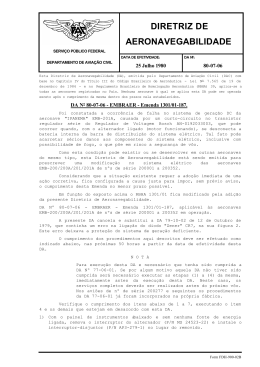
1.2 - Princípio de funcionamento
1.2 - Principles of operation
O regulador de tensão é alimentado por 2 enrolamentos
auxiliares. Um dos enrolamentos (5A) apresenta uma curva característica de shunt (tensão proporcional à tensão
do alternador), o outro (5B) apresenta uma curva característica de série (tensão proporcional à corrente do estator).
No momento do arranque, devido ao magnetismo remascente da excitactriz (1), cria-se uma corrente no induzido
da excitactriz. Essa corrente, rectificada na ponte de díodos (2), alimenta o enrolamento principal do rotor (3). Além
da tensão induzida no enrolamento do estator do alternador (4) (tensão de saída), é
(2)
também induzida uma ten(1)
são no enrolamento auxiliar (5A), monofásico.
A tensão induzida na bobinagem auxiliar alimenta
através do regulador (6) o
indutor da excitactriz (7).
(7)
O regulador de tensão (6)
(6)
controla a corrente de excitação da excitatriz em função da tensão de saída do
alternador. Em carga, sobregarga ou curto-circuito a
bobinagem auxiliar (5B),
responde com um aumento
da corrente de excitação
(efeito booster).
The AVR is fed by 2 auxiliary windings located in the stator.
One of the windings (5A) with shunt characteristic (delivering a voltage proportional to the generator's output voltage) and the second one (5B) with a series characteristic
(delivering a voltage proportional to the generator's output
current).
When starting, the residual magnetism creates a current in
the exciter armature(1). This current is rectified by the
rotating diodes (2) and feeds the main field (3).
The induced voltage in the auxiliary winding (5A) (single
phase)is then used to increase
the excitation power via the
AVR (6) to the exciter field (7)
to ensure a rapid and smooth
build up of output voltage in the
main stator winding (4).
(3)
(4)
The voltage sensing for the
(5A)
AVR is taken from the output
leads (phase V-W). On load,
(5B)
overload or short circuit the
auxiliary winding (5B) supplies
an additional excitation voltage (the booster effect).
2 - INSTALAÇÃO
2 - INSTALLATION
Quando fizer a recepção do seu alternador, verifique se
apresenta marcas de pancadas ou danos. Se apresentar
evidência de choques, é provável que o alternador apresente danos internos; nesse caso aconselhamos que coloque
o problema junto da empresa que assegurou o transporte.
Unpack the alternator, check for any damage to the crate
pallet or plywood shipping container. If any damage is visible, it is possible the alternator itself has been damaged.
Such damage should be reported to the shipping carrier.
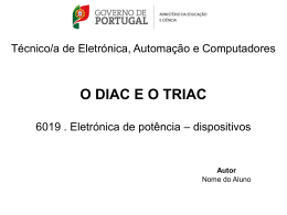
2.1 - Escolha do local - Ventilação
2.1 - Location - Cooling
O local de instalação do alternador deve ser tal que a temperatura ambiente não ultrapasse os 40°C, considerando o
funcionamento para potências Standard (para temperaturas superiores a 40°C, deve ser aplicado um coeficiente
p/ a redução da potência). Devem ser criadas condições
para que ar fresco isento de poeiras e humidade, atinja facilmente as grelhas de ventilação situadas no local oposto
ao do acoplamento.
Deve ser evitada a reciclagem de ar quente pelas grelhas
do lado oposto ao acoplamento. O ar quente proveniente
das grelhas próximas do acoplamento (saída), do motor
térmico de accionamento e
dos gases de escape, deve
ser encaminhado para o Saida de ar quente
Hot air outlet
exterior.
The area in which the alternator is installed shall be such
that the ambient temperature never exceeds 40°C (at
normal ratings). For higher ambients a derating factor
should be applied.
Fresh air, free from humidity and dust, must circulate easily
through the screen at the non-drive end of the alternator.
The recycling of heated air, from the D.E. or circulating from
the prime mover, should be avoided as far as possible.
Ensure adequate ventilation for a good air flow at all times.
Plano de instalação
;;;;;;;;;;;;;
yyyyyyyyyyyyy
yyyyyyyyyyyyy
;;;;;;;;;;;;;
;;;;;;;;;;;;;
yyyyyyyyyyyyy
;;;;;;;;;;;;;
yyyyyyyyyyyyy
;;;;;;;;;;;;;
yyyyyyyyyyyyy
;;;;;;;;;;;;;
yyyyyyyyyyyyy
;;;;;;;;;;;;;
yyyyyyyyyyyyy
;;;;;;;;;;;;;
yyyyyyyyyyyyy
;;;;;;;;;;;;;
yyyyyyyyyyyyy
;;;;;;;;;;;;;
yyyyyyyyyyyyy
;;;;;;;;;;;;;
yyyyyyyyyyyyy
;;;;;;;;;;;;;
yyyyyyyyyyyyy
;;;;;;;;;;;;;
yyyyyyyyyyyyy
;;;;;;;;;;;;;
yyyyyyyyyyyyy
;;;;;;;;;;;;;
yyyyyyyyyyyyy
;;;;;;;;;;;;;
yyyyyyyyyyyyy
;;;;;;;;;;;;;
yyyyyyyyyyyyy
;;;;;;;;;;;;;
yyyyyyyyyyyyy
;;;;;;;;;;;;;
yyyyyyyyyyyyy
;;;;;;;;;;;;;
yyyyyyyyyyyyy
;;;;;;;;;;;;;
yyyyyyyyyyyyy
;;;;;;;;;;;;;
yyyyyyyyyyyyy
;;;;;;;;;;;;;
yyyyyyyyyyyyy
;;;;;;;;;;;;;
yyyyyyyyyyyyy
;;;;;;;;;;;;;
yyyyyyyyyyyyy
;;;;;;;;;;;;;
yyyyyyyyyyyyy
;;;;;;;;;;;;;
yyyyyyyyyyyyy
;;;;;;;;;;;;;
yyyyyyyyyyyyy
;;;;;;;;;;;;;
yyyyyyyyyyyyy
;;;;;;;;;;;;;
yyyyyyyyyyyyy
;;;;;;;;;;;;;
yyyyyyyyyyyyy
;;;;;;;;;;;;;
yyyyyyyyyyyyy
;;;;;;;;;;;;;
yyyyyyyyyyyyy
;;;;;;;;;;;;;
yyyyyyyyyyyyy
;;;;;;;;;;;;;
yyyyyyyyyyyyy
;;;;;;;;;;;;;
yyyyyyyyyyyyy
;;;;;;;;;;;;;
yyyyyyyyyyyyy
;;;;;;;;;;;;;
yyyyyyyyyyyyy
;;;;;;;;;;;;;
yyyyyyyyyyyyy
;;;;;;;;;;;;;
yyyyyyyyyyyyy
;;;;;;;;;;;;;
yyyyyyyyyyyyy
;;;;;;;;;;;;;
yyyyyyyyyyyyy
;;;;;;;;;;;;;
yyyyyyyyyyyyy
;;;;;;;;;;;;;
yyyyyyyyyyyyy
;;;;;;;;;;;;;
yyyyyyyyyyyyy
;;;;;;;;;;;;;
yyyyyyyyyyyyy
;;;;;;;;;;;;;
yyyyyyyyyyyyy
;;;;;;;;;;;;;
yyyyyyyyyyyyy
;;;;;;;;;;;;;
yyyyyyyyyyyyy
;;;;;;;;;;;;;
yyyyyyyyyyyyy
;;;;;;;;;;;;;
yyyyyyyyyyyyy
;;;;;;;;;;;;;
yyyyyyyyyyyyy
yyyyyyyyyyyyy
;;;;;;;;;;;;;
yyyyyyyyyyyyy
;;;;;;;;;;;;;
Antes de proceder à instalação da máquina, deve retirar todos os papéis de protecção colocados nas aberturas durante a pintura.
Installation
Acesso ao regulador de tensão
Access to voltage regulator
Entrada de ar fresco
Cool air inlet
Precautions to be taken before installation
Make sure air inlet and outlet openings are clear.
5
Alternador
LSA 46.1 / 47.1 AREP. 4 Polos
Alternator
LSA 46.1 / 47.1 AREP. 4 Pole
2.2 - Ensaios Eléctricos
2.2 - Electrical checks
Antes da entrada em serviço, é aconshelhável verificar o
isolamento eléctrico do alternador entre cada fase e a massa entre fases. O regulador de tensão deve estar desconectado para o ensaio, a ser efectuado com um mégaohmimetro (500 V dc). O isolamento normal com o alternador
frio é de > 10 mégaohms.
Before putting the machine into service, an insulation
check between phase and earth and between phases is recommended. For this operation the A.V.R. must be disconnected. This test should be done with a "megger" using
500 V.d.c. The insulation (machine cold) should normally
be >10 meghoms.
ATENÇÃO. É absolutamente proibido colocar em serviço qualquer alternador, se este apresentar um isolamento inferior a 1 mégaohm no enrolamento do estator
e 100 000 ohms nos outros enrolamentos.
Caso sejam medidos valores inferiores aos referidos, é
provável que a máquina tenha estado parada durante muito tempo, a zona apresentar características altamente higrométricas (beira-mar, regiões tropicais) projecções de
água, nevoeiros, etc...
Para recuperar os valores mínimos de isolamento eléctrico
referidos, podem ser utilizados diversos métodos:
a) Proceda à secagem da máquina, colocando-a durante
24 horas em estufa à temperatura de 100 a 110 °C.
b) Aplique ar quente na entrada de ventilação assegurando
a rotação da maquina com o indutor desligado.
c) Desligue o regulador de tensão e proceda do seguinte
modo:
- curto-circuite os três bornes de saída (potência) com
shunts capazes de suportar a corrente nominal (não é
aconselhável ultrapassar 6 A/mm2)
- instale uma pinça amperimétrica para controlo da corrente no shunt (curto-circuito).
- aplique aos bornes dos indutores da excitação, respeitando as respectivas polaridades, uma bateria de 48 V em
série com um reóstato de 10 Ohms (250 Watts).
- retire todas as tampas do alternador, nomeadamente: a
tampa da placa de bornes, a grelha de protecção, etc ...
- coloque o alternador à velocidade nominal e regule a excitação para o ponto médio do reóstato referido, de modo a
obter a intensidade nominal nas ligações de curto circuito.
Nota : Paragens prolongadas
Para evitar as dificuldades acima expostas recomenda-se
a utilização de uma resistência de aquecimento, sendo no
entanto conveniente a colocação regular em serviço para
efeitos de manutenção. (As resistências de aquecimento
não serão eficazes se estiverem em funcionamento permamente durante o período de paragem da máquina.)
CAUTION : No machine whether new or used sho uld be
operated if insulation is less than 1 meghom for stator
and 100,000 ohms for other windings.
2.3 - Ensaios mecânicos
2.3.1 - Sentido de rotação
O alternador funciona correctamente nos dois sentidos de
rotação. O sentido de rotação standard é o sentido horário
(sequência de fases 1 - 2 - 3 ). No sentido de rotação antihorário, a sequência de fases 1 - 2 - 3 é obtida pela permuta
da fase 2 com a fase 3.
2.3.2 - Acoplamento semi-elástico do alternador de
duas chumaceiras
É importante realizar um alinhamento cuidadoso das 2 máquinas para que os desvios de concentricidade e de paralelismo dos 2 pratos de acoplamento não excedam 0,1 mm.
ATENÇÃO : Este alternador foi equilibrado com 1/2
chaveta
2.3.3 - Acoplamento do alternador com uma chumaceira
Antes de acoplar as 2 máquinas, verifique a respectiva
compatibilidade:
- efectue a análise torcional da linha de eixos
- verifique as dimensões dos volantes e resguardos, da
flange, discos e cotas . Depois do acoplamento verifique
se existem desvios laterais nos veios.
6
If lower, the machine must be dried until the minimum value
is obtained.
To get to the minimum value, there are several methods:
a) Bake the machine for 24 hours in an oven at 100°C .
b)Dry out the machine with a stream of hot air.
c) Disconnect the voltage regulator
- short-circuit the three output (power) terminals through
connections capable of carrying the rated current (if
possible do not exceed 6 A/mm2)
- with an appropriate ammeter, monitor the current flowing
in the short circuited connections.
- connect a 48 volt storage battery to the field winding
terminals of the exciter (respecting polarities), fitted in
series with a rheostat of about 10 ohms (250 Watts).
- open completely all the apertures of the alternator :
terminal box panels, protection screens etc ........
- start up the machine at its rated speed and adjust its
excitation through the rheostat in order to obtain the rated
current in the short-circuited connections.
Note : lengthy down-times:
In order to avoid such problems, it is recommended either
to fit anti-condensation heaters or to run the machine
periodically.
(During long down-times, the anti-condensation heaters
must operate continuously.)
2.3 - Mechanical checks
2.3.1 - Direction of rotation
The alternator can be driven in either direction of rotation
but standard phase sequence is 1 - 2 - 3 , when rotation is
clockwise looking on the drive end.
For anti-clockwise rotation transpose phases 2 and 3 to get
1.2.3 phase sequence.
2.3.2 - Two-bearing alternator semi-flexible coupling
Careful alignment of the machines by measuring the
concentricity and parallelism of the two parts of the coupling is recommended. The difference between the
readings shall not exceed the specified values (say 0.1
mm).
WARNING : This generator has been balanced with an
half key .
2.3.3 - Single bearing alternator coupling
Before coupling the two machines, make sure of their
compatibility by :
- torsional analysis
- checking all dimensions of flywheel and flywheel housing
and flange, discs and spacing. After coupling, check lateral
play of crankshaft.
Alternador
LSA 46.1 / 47.1 AREP. 4 Polos
Alternator
LSA 46.1 / 47.1 AREP. 4 Pole
3 - ENTRADA EM SERVIÇO
3 - STARTING UP
3.1 - Verificações prévias
3.1 - Preliminary checks
3.1.1 - Verificações mecânicas
Antes do primeiro arranque, verifique se:
- os parafusos de fixação das sapatas de apoio estão apertados,
- o acoplamento está feito correctamente,
- as entradas de ar estão desobstruídas e a circulação de ar
de refrigeração está a ser efectuada,
- as grelhas de protecção e o carter estão devidamente colocados,
- para os alternadores com 1 chumaceira o binário de aperto
dos parafusos dos discos de acoplamento é de 15.8 m.daN
3.1.1 - Mechanical checks
Before starting up, check:
- that all foot and flange bolts are tightened.
- that the cooling air circulates freely around and through
the machine,
- that all louvres, guards, etc., are correctly fitted
- for single bearing alternators, that discs are fastened to
the coupling hub with bolts torqued at 15.8 m.daN
- for two bearing alternators, that coupling is correct
3.1.2 - Verificações eléctricas
Verifique se :
- na saída de potência do alternador está instalado um dispositivo de corte para protecção contra sobreintensidade e
corrente diferencial, de acordo com a regulamentação vigente,
- a ligação da máquina à rede de alimentação deve ser realizada de modo que
os cabos fiquem adjacentes, com as porcas
dos bornes bem apertadas,
- a ligação de cabos e
barretas devem corresponder às tensões
de funcionamento
pretendidas,
- os dispositivos de protecção estão correctamente ligados
e operacionais,
- no caso de um regulador no exterior, as ligações com o alternador deverão ser efectuadas de acordo com o esquema apropriado,
- não ocorram curto-circuitos entre fases ou fase neutro,
entre os bornes de saída do alternador e o quadro de
controlo do grupo electrogéneo (parte do circuito que não
se encontra protegida por disjuntores ou relés específicos).
3.2 - Esquema de ligações interiores
Os esquemas de ligações desenvolvidos nas páginas 8 a
11 correspondem às soluções standard.
No caso de alterações aos esquemas referidos convêm
confirmar nas especifícações do alternador se não se ultrapassam os valores máximos admissíveis.
3.2.1 - Placa de ligações
A) Ligações de potência
- Bornes de massa ; 1 borne (Ø 10 mm:46.1), (Ø 12 mm :
47.1) na proximidade dos bornes isolados, 1 borne Ø 10
mm sobre um dos apoios do alternador.
-Os restantes terminais (excepto o da massa) não estão
marcados.
-Os feixes de fios provenientes dos enrolamentos são marcados de T1 a T12 para os alternadores a "12 fios": pode haver diversos conjuntos de fios marcados da mesma forma.
- Os feixes de fios provenientes do enrolamento principal,
são sempre ligados aos mesmos terminais qualquer que
seja o esquema de ligações dos enrolamentos.
- SAÍDAS DO ALTERNADOR : A ligação dos cabos de saída (para a carga) é feita pelos terminais U1, V1, W1 (fases
L1, L2, L3) N (neutro ou ponto médio) e borne de terra, para utilização em regime trifásico ou monofásico.
A saída standard de cabos é feita do lado esquerdo do alternador. A saída pela dtª pode ser encomendada à fábrica.
3.1.2 - Electrical checks
Make sure:
- a suitable electrical protection device is fitted in the output
circuit for safety reasons (in line with the codes of practice
in force within the country where the alternator is installed)
- the machine-to-power supply interconnection is made
according to the drawing (terminal lugs adjacent to each
other). Ensure before start up that terminal nuts are
properly tightened.
- the terminal links
correspond to the voltage
required,
- the control panel
protection equipment is
correctly set
- for separately fitted
regulator, that
connections between alternator and cabinet correspond to
connection diagram,
- there is no short-circuit due to wrong connections either
LL. or L.N between the terminals of the alternator and the
power switch or breaker (this part of the circuit is not
protected by the breaker)
3.2 - Internal connection diagramm
The connection diagrams below (pages 8/11) give the most
useful standard connections.
Check the output kVA available for the selected voltage
with the catalogue .
3.2.1 - Terminal box
A) High Amp connections
- Earthing terminals = 1 terminal screw (Ø 10 mm:46.1), (Ø
12 mm : 47.1) close to output terminals, 1 terminal Ø 10 mm
on one alternator foot.
- Terminals (except earthing terminals) are not marked
- Bundles of wires coming from the windings are marked T1
to T12 for "12 wire" alternators. Several cables may be
identically marked.
- The bundles of wires coming from the windings are always connected to the same terminals, whatever the output
connections.
- Output terminals : The connection of output cables is
made by using terminals U1,V1,W1 for phases L1, L2 ,L3
and N (neutral or middle point) and earthing terminal for
either 3 phase or single phase application.
The standard cable output is on the left side viewed from
the D.E. Output on the right is possible, on request.
7
Alternador
LSA 46.1 AREP. 4 Polos
Alternator
LSA 46.1 AREP. 4 Pole
3.2.2 - Esquema de ligações LSA 46.1 : 6 Fios
3.2.2 - Internal connection diagram LSA 46.1 : 6 wires
CAMPO MAG. INDUZIDO / MAIN FIELD
Indutor
Exciter field
-
Vermelho/Red
Preto/Black
+
Verde/Green
Induzido/Armature
Enrolamentos aux.
Aux. windings
Amarelo/Yellow
Resistência Varíavel
Excitatriz/Exciter
P2
- Azul/Blue
+ Branco/White
ESTATOR : 6 fios (marcados 1 a 6)
6 wires (labelled 1 to 6)
1
2
3
4
5
6
S2
S1
P1
ST3
OPÇÃO
1A
T.I (C.T) - PH 1
(ligação Y coupling)
In - Secundário 1 A
R 448
4
P2
P5
P4
50Hz 60Hz
F2
ST5
ST2
F1
P3
P2
ST1
P1
S1 S2
X2
Z1
X1
Z2
E+
E0V
110V
220V
380V
P1
Barra de
neutro
Neutral bar
170 - 260 V
340 - 520 V
w
L3 (W)
v
L2 (V)
Rhe (Opção)
Remote voltage trimmer
ST4
Rhe
Ajuste de tensão ext. (trimmer)
(retirar shunt ST4)
Remote voltage adjustment
(remove ST4)
P1 : Estatismo - Quadrature voltage droop
P2 : Tensão - Voltage
P3 : Estabilidade - Stability
P4 : Limiar de sub-velocidade - Frequency threshold + LAM
P5 : Valor máx. da corrente de excitação / Excitation current ceiling
ST1: Detecção de falta de fase (monofásico) - Single phase voltage sensing
ST2: Tempo de resposta - Recovery time: normal
Rápida -Fast
ST3: Frequência - Frequency selection
ST4: Potenciómetro externo - Remote trimmer
ST5: Com / with LAM
sem / without LAM
depois / after n° 200
F1- F2: Fusíveis / Fuses : 250 V . 10 A
Opcional:
- 3 phase sensing: ST1
( com módulo opcional - with optional module)
Detecção de falta de fase (trifásica)
ESQUEMA DAS LIGAÇÕES INTERNAS DO REGULADOR DE TENSÃO
WIRING AND A.V.R. CONNECTION DIAGRAM
8
Extraído do esquema / Extracted from
N°: 2259.11.92(0)
Alternador
LSA 46.1 AREP. 4 Polos
Alternator
LSA 46.1 AREP. 4 Pole
3.2.3 - Esquema de ligações LSA 46.1 : 12 Fios
3.2.3 - Internal connection diagram LSA 46.1 : 12 wires
CAMPO MAG. DO INDUZIDO / MAIN FIELD
Indutor
Exciter field
-
Vermelho/Red
Pretor/Black
+
Verde/Green
Induzido/Armature
Enrolamentos aux.
Aux. windings
Amarelo/Yellow
Resistência Variável
Excitatriz/Exciter
ESTATOR : 12 fios (marcados 1 a 12)
12 wires (labelled 1 to 12)
1
7
2
8
3
9
4
10
5
11
6
12
P2
- Azul/Blue
S2
+ Branco/White
S1
P1
ST3
R 448
P5
P4
T.I (C.T) - PH 1
( Y ligado D / Y// ligado A)
In - Secundário 1A (ligado D)
1A
50Hz 60Hz
F2
ST5
ST2
F1
P3
P2
OPÇÃO
ST1
P1
S1 S2
X2
Z1
X1
Z2
E+
E0V
110V
220V
380V
10
P2
P1
Neutro
Neutral
170 - 260 V
340 - 520 V
w
L3 (W)
v
L2 (V)
Rhe (Opção)
Remote voltage trimmer
ST4
Rhe
Ajuste de tensão ext. (trimmer)
(Retirar shunt ST4)
Remote voltage adjustment
(remove ST4)
P1 : Estatismo - Quadrature voltage droop
P2 : Tensão - Voltage
P3 : Estabilidade - Stability
P4 : Limiar de sub-velocidade - Frequency threshold + LAM
P5 : Valor máx. da corrente de excitação / Excitation current ceiling
ST1 : Detecção de falta de fase (monofásica) - Single phase voltage sensing
ST2 : Tempo de resposta - Recovery time: normal
Rápida -Fast
ST3 : Frequência - Frequency selection
ST4 : Potenciómetro externo - Remote trimmer
ST5 : Com / with LAM
sem / without LAM
depois / after n° 200
F1- F2 : Fusíveis / Fuses : 250 V . 10 A
Opcional: Detecção de falta de fase (trifásica) - 3 phase sensing: ST1
(com módulo opcional - with optional module)
ESQUEMA DAS LIGAÇÕES INTERNAS DO REGULADOR DE TENSÃO
WIRING AND A.V.R. CONNECTION DIAGRAM
Extraído do esquema / Extracted from
N°: 2261.11.92(0)
9
Alternador
LSA 47.1 AREP. 4 Polos
Alternator
LSA 47.1 AREP. 4 Pole
3.2.4 - Esquema de ligações LSA 47.1 : 6 Fios
3.2.4 - Internal connection diagram LSA 47.1 :6 wires
ESTATOR 6 FIOS / WIRES
U1
CAMPO MAGNÉTICO DO INDUZIDO/MAIN FIELD
Resistência Variável
Aux. windings
Exciter field
T1
X1 Z2
W1
T2
T4 C10
Preto/Black
-
X2
Verde/Green
Vermelho/Red
Z1
Amarelo/Yellow
Induzido/Armature
+ Indutor
V1
Enrolamentos aux.
Excitatriz/Exciter
T5 C11
V2
P2
- Azul/Blue
T3
T6 C12
W2
T.I. / C.T. ( Opção/Optional)
+ Branco/White
P1
ST3
U2
R 448
P5
50Hz 60Hz
P4
F2
ST5
ST2
F1
P3
ST1
P2
P1
S1 S2
X2
Z1
X1
Z2
E+
E0V
110V
220V
380V
Desexcitação
(não fornecido/not supplied)
OPÇÃO
T.I (C.T) - PH 1 (T4)
w
L3
v
Ajuste exterior de tensão (retirar ST4)
Remote voltage adjustment (remove ST4)
P1 : Estatismo - Voltage droop
Neutral
Neutral
L2
S2 T.I. / C.T. ( Opção/Optional)
S1
Rhe
Opção /Optional
Rhe:
ST4
P2
170 - 260 V (50/60Hz)
340 - 520 V(50/60Hz)
P2 : Tensão - Voltage
T4 ou C10*
(ligação Y coupling)
In/2 Secundário 1 A
P1
* (C10 até 12/93; depois T4)
* (C10 until 12/93; after T4)
Disposição dos terminais de sáida
Position of output terminals
AV (D.E)
C11
C10
C12
T5
T4
T6
T3
T2
T1
P3 : Estabilidade - Stability
P4 : Limiar de sub-velocidade - Frequency threshold + LAM
W1
L3
P5 : Valor máximo da corrente da excitação / Excitation current ceiling
L2
ST1: Detecção de falta de fase (monofásica) - Single phase voltage sensing
ST2: Tempo de resposta - Recovery time: normal
V1
/ Rápido -Fast
L1
ST3: Frequência - Frequency
U1
ST4: Potenciómetro externo - Remote trimmer
ST5 : Com / with LAM
sem / without LAM
depois / after n° 200
AR (N.D.E)
F1- F2: Fusíveis / Fuses : 250 V . 10 A
Opcional : Detecção trifásico - 3 phase sensing : ST1
( com módulo opcional - with optional module)
ESQUEMA DAS LIGAÇÕES INTERNAS DO REGULADOR DE TENSÃO
WIRING AND A.V.R. CONNECTION DIAGRAM
10
Extraído do esquema / Extracted from
N°: 2277.01.93(A)
Alternador
LSA 47.1 AREP. 4 Polos
Alternator
LSA 47.1 AREP. 4 Pole
3.2.5 - Esquema de ligações LSA 47.1 : 12 Fios
3.2.5 - Internal connection diagram LSA 47.1 : 12 wires
ESTATOR 12 FIOS / WIRES
U1
Preto/Black
T6
T12
T11
T10
T5
P2
W6
V6
T.I. / C.T. (Opcional / Optional)
P1
- Azul / Blue
T3
C11
T2
C10
T4
T9
T8
T1
X1 Z2
Verde/Green
Vermelho/Red
-
Exciter field
X2
Amarelo/Yellow
Z1
W1
T7
Aux. windings
Resistência variável
Induzido/Armature
+ Indutor
V1
Enrolamentos aux.
Excitatriz/Exciter
C12
CAMPO MAG. DO INDUZIDO / MAIN FIELD
+ Branco / White
U6
ST3
R 448
P5
50Hz 60Hz
P4
F2
ST5
ST2
F1
P3
ST1
P2
P1
S1 S2
X2
Z1
X1
Z2
E+
E0V
110V
220V
380V
Desexcitação
(não fornecido / not supplied)
OPCIONAL
w
L3
v
L2
T.I (C.T) - PH 1
(Y ligação D / Y// ligação A)
Prim. In/2 (ligação D)
Secundário 1 A
C10
P2
170 - 260 V (50/60Hz)
340 - 520 V(50/60Hz)
P1
Neutro
Neutral
T10
S2 T.I. / C.T. ( Opcional / Optional)
S1
ST4
Rhe:
Rhe
Opção /Optional
Ajuste de tensão ext (por substituição do shunt ST4)
Remote voltage adjustment (remove ST4)
P1 : Estatismo - Voltage droop
P2 : Tensão - Voltage
Disposição dos terminais de saída
Position of output terminals
AV (D.E)
P3 : Estabilidade - Stability
P4 : Limiar de sub-velocidade - Frequency threshold + LAM
P5 : Valor máximo da corrente de excitação / Excitation current ceiling
C12
T6
C11
T5
T12
C10
T4
T9
T3
T2
T8
T7 T1
ST1 : Detecção de falta de fase (monofásica) - Single phase voltage sensing
ST2 : Tempos de resposta - Recovery time: normal
/Rápida -Fast
L3
W1
T11
L2
ST3 : Frequência - Frequency
V1
ST4 : Potenciómetro externo - Remote trimmer
ST5 : Com / with LAM
sem / without LAM
T10
L1
depois /after n° 200
U1
F1- F2: Fusíveis / Fuses : 250 V . 10 A
Opcional: Detecção de falta de fase (trifásica) - 3 phase sensing: ST1
AR (N.D.E)
(com módulo opcional - with optional module)
ESQUEMA DAS LIGAÇÕES INTERNAS DO REGULADOR DE TENSÃO
WIRING AND A.V.R. CONNECTION DIAGRAM
ExtraÍdo do esquema / Extracted from
N°: 2215.05.92(0)
11
Alternador
LSA 46.1 AREP. 4 Polos
Alternator
LSA 46.1 AREP. 4 Pole
3.3 - Esquema de ligações na placa de bornes
3.3 - Connection of output terminals
3.3.1 - Ligações dos bornes : LSA 46.1 - 6 fios
3.3.1 - Output terminals : LSA 46.1 - 6 fils
Código de ligações/Connection code
L1(U)
D
Tensão / Tension L.L
6 FIOS - 6 WIRES
Estrela
Star
1
Ligações de fábrica / Factory connection
AV (D.E)
Trifásico
Three phase
Para tensões especiais
4
V2
N
For special voltages
6
U2
5
3
2
W2
Código de ligações/Connection code
Mono ou trifásico
Single or three
6
phase
Tensão / Tension L.L
1
5
4
L1
W2
L2(V)
Tensão / Tension L.L
2
V1
L2
1
U1
L1
*
Ligações de fábrica / Factory connection
6 FIOS - 6 WIRES
AV (D.E)
M
5
Para tensões especiais
V2
For special voltages
U2
4
6
L2(V)
5
L3
( )
M
4
W1
AR (N.D.E)
Monofásico - ZIG ZAG
Single phase - DOG LEG
Solução desaconselhada
Inadvisable connection
3
U2
2
Código de ligações/Connection code
W2
2
AR (N.D.E)
ESQUEMA DAS LIGAÇÕES INTERNAS DO REGULADOR DE TENSÃO
WIRING AND A.V.R. CONNECTION DIAGRAM
(*) A fabrica fornece a pedido um conjunto de shunts flexíveis e barras de ligações apropriadas para realizar as montagens descrítas.
O alternador standard vem equipado de 3 conjuntos de saída e uma barra de neutro.
12
U1
V2
Para tensões especiais
L3(W)
L3(W)
1
6
6
5
3
L2
Ligações de fábrica / Factory connection
4
1
V1
AV (D.E)
Triângulo
Delta
3
6
2
4
N
For special voltages
G
L3
6 FIOS - 6 WIRES
L1(U)
C
W1
AR (N.D.E)
L2(V)
L3(W)
3
5
3
W1
L3
2
V1
L2
1
U1
( )
*
Extraído do esquema / Extracted from
N°: 2260.11.92(0)
(*) Upon request optional links and special copper bars can
be delivered by the factory to make these connections.
Standard alternator is fitted with 3 output bars, and 1 neutral bar.
Alternador
LSA 47.1 AREP. 4 Polos
Alternator
LSA 47.1 AREP. 4 Pole
3.3.2 - Ligações dos bornes : LSA 47.1 - 6 fios
3.3.2 - Output terminals : LSA 47.1 - 6 fils
Tensão / Tension L.L
Código de ligações / Connection code
D
Bobinagem
Winding
L1(U)
Trifásico
Three phase
6S
T1
Ligações de fábrica / Factory connection
50 Hz
60 Hz
380 - 415
440 - 480
AV (D.E)
T4
T5 T6
V2
W1
C11
C10
T5
8S
T6
347
V1
380 - 416
L1
C12
L2(V)
L3(W)
6S
T6
50 Hz
Ligações de fábrica / Factory connection
60 Hz
AV (D.E)
T4
T5 T6
-
220 - 240
T1
T3
N
AR (N.D.E)
Tensão / Tension L.L
Bobinagem
Winding
L1(U)
U1
Terminais do regulador : 0. 380V
AVR terminals
Código de ligações / Connection code
Trifásico
Three phase
T2
T1 T3
V2
W1
U2
V1
L3
C11
8S
T4
200
220 - 240
L2
C10
U1
W2
T5
L2
W2
T2
T3
C
L3
U2
T4
T2
L1
C12
L2(V) Terminais do regulador : 0. 220V
L3(W)
Tensão / Tension L.L
Código de ligações / Connection code
Bobinagem
Winding
C
Monofásico
Single phase
6S
T6
50 Hz
60 Hz
AV (D.E)
T4
T5 T6
-
220 - 240
*
Ligações de fábrica / Factory connection
T1
T3
( )
AR (N.D.E)
AVR terminals
T2
T1 T3
V2
W1
U2
V1
L3
C11
T4
8S
200
220 - 240
T2
L2
C10
W2
T5
L3(W)
T2
T1 T3
U1
C12
L2(V) Terminais do regulador : 0. 220V
AVR terminals
AR (N.D.E)
ESQUEMA DAS LIGAÇÕES INTERNAS DO REGULADOR DE TENSÃO
WIRING AND A.V.R. CONNECTION DIAGRAM
(*) A fábrica fornece a pedido um conjunto de shunts
flexíveis e barras de ligação apropriadas para realizar as
montagens descritas.
O alternador standard vem equipado com 3 conjuntos de
saída e uma barra de neutro.
( )
*
Extraído do esquema / Extracted from
N°: 2278.01.93(0)
(*) Upon request optional links and special copper bars can
be delivered by the factory to make these connections.
Standard alternator is fitted with 3 output bars, and 1 neutral bar.
13
Alternador
LSA 46.1 / 47.1 AREP. 4 Polos
Alternador
LSA 46.1 / 47.1 AREP. 4 Pole
3.3.3 - Ligações dos bornes : LSA 46.1/47.1 - 12 fios
3.3.3 - Output terminals : LSA 46.1/47.1 - 12 fils
Código de ligações/Connection code
Bobinagem
Winding
L1(U)
A
1
Trifásico
Three phase
Tensão / Tension L.L
50 Hz
12 FIOS - 12 WIRES
60 Hz
AV (D.E)
7
4
N
10
12
5
6
190 - 208 208 - 240
7
220 - 230
8
-
2
9
8
3
L2(V)
1
9
11
5
8
10
4
7
3
4
190 - 208
9
Tensão / Tension L.L
50 Hz
60 Hz
6
380 - 415 416 - 480
7
440 - 460
-
347
380 - 416
8
11
2
L3(W)
L2(V)
FF
T2
12 FIOS - 12 WIRES
AV (D.E)
12
6
9
11
5
8
10
4
7
3
7
T3
T11
T5
T1
T4
T9
T7
8
T10
L1(U)
L2(V)
M
M
T4
T7
T3
L3(W)
T8 T5
T2
7
8
T10
T11
U1
L1
1
1/2
1/2
220 - 240
110 - 120
240 - 260
120 - 130
200
100
Ligações de fábrica / Factory connection
60 Hz
12 FIOS - 12 WIRES
AV (D.E)
12
240
120
-
3
9
6
W1
11
2
5
220 - 240
110 - 120
10
4
8
V1
1
7
L1
U1
M
1/2
1/2
1/2
*
50 Hz
220 - 240
110 - 120
240 - 260
120 - 130
200
100
Ligações de fábrica / Factory connection
60 Hz
220 - 240
110 - 120
Terminais do regulador : 0V.(L3) - 220V(L2)
AVR terminals
ESQUEMA DAS LIGAÇÕES INTERNAS DO REGULADOR DE TENSÃO
WIRING AND A.V.R. CONNECTION DIAGRAM
12 FIOS - 12 WIRES
AV (D.E)
240
120
L2(V)
Solução desaconselhada em monofásico
Inadvisable connection in single phase
L2
( )
Tensão / Tension L.L
6
T1
T9
T6
1/2
50 Hz
Bobinagem
Winding
L1(U)
T12
L2
AVR terminals
Código de ligações/Connection code
Mono ou
Trifásico
Single or
Three
phase
V1
2
Terminais do regulador : 0V.(L1) - 220V(L2)
Tensão LM=1/2 tensão LL
Voltage LM=1/2 voltage LL
F
L3
N
Tensão / Tension L.L
6
T12
W1
AVR terminals
Bobinagem
Winding
T8
T6
L1
Terminais do regulador : 0V.(L3) - 380V(L2)
Código de ligações/Connection code
Monofásico
Single phase
U1
1
8
6
L2
Ligações de fábrica / Factory connection
5
3
V1
N
10
12
L3
2
7
N
W1
Terminais do Regulador : 0V.(L3) - 220V(L2)
Bobinagem
Winding
L1(U)
D
14
6
AVR terminals
Código de ligações/Connection code
Trifásico
Three phase
-
12
11
6
L3(W)
Ligações de fábrica / Factory connection
12
6
3
9
11
2
5
8
W1
L3
V1
L2
U1
L1
1
10
4
7
M
( )
*
Extraído do esquema / Extracted from
N°: 2262.11.91/1(0)
Alternator
LSA 46.1 / 47.1 AREP. 4 Pole
Alternador
LSA 46.1 / 47.1 AREP. 4 Polos
Tensão / Tension L.L
Código de ligações / Connection code
Bobinagem
Winding
Monofásico
Single phase
G
6
1
12
6
M
7
7
4
3
10
9
L3(W)
5
2
11
8
8
L2(V)
1/2
1/2
1/2
50 Hz
220 - 240
110 - 120
240 - 260
120 - 130
200
100
Ligações de fábrica / Factory connection
60 Hz
240
120
-
12 FIOS - 12 WIRES
AV (D.E)
12
11
220 - 240
110 - 120
3
9
6
8
2
5
7
Terminais do regulador : 0V.(L3) - 220V(L2)
AVR terminals
Ligação desaconselhada
Connection not recommended
L3
V1
L2
1
10
4
W1
U1
M
( )
*
Extraído do esquema / Extracted from
ESQUEMA DE LIGAÇÕES DO REGULADOR
WIRING AND A.V.R. CONNECTION DIAGRAM
N°: 2262.11.91/2(0)
(*) Pode ser fornecido por encomenda um conjunto de
(*) Upon request optional links and special copper bars
shunts flexíveis e barras apropriadas para efectuar as ligações.
O equipamento standard do alternador inclui três barras
de saída, 6 barras de ligação e uma barra de neutro.
can be delivered by the factory to make these connections.
Standard alternators are fitted with 3 output bars, 6
connection bars, and 1 neutral bar.
4 - MANUTENÇÃO
4 - MAINTENANCE
4.1 - Ventilação
4.1 - Cooling circuit
É necessário verificar se a circulação de ar não é pertubada por qualquer obstrução parcial das grelhas de aspiração e expulsão tais como : lamas, poeiras, fuligem,
etc ....
It is recommended to check if the cooling air circulation
is not restricted.
4.2 - Bearings
4.2 - Rolamentos
4.2.1 - Bearings sealed for life
Approximate grease life : 20,000 hours or 3 years
Temperature rise of ball bearings :
Periodically check that the temperature of the bearings
does not exceed 60°C above ambient temperature.
If higher, it is necessary to stop the machine to proceed
to a general inspection. Temperature detectors can be
fitted on request.
4.2.1 - Rolamentos sem lubrificação.
Duração média da massa lubrificante (conforme utilização) = aproximadamente 20 000 horas ou 3 anos.
Controlar o aumento de temperatura nos rolamentos
que não deve ultrapassar os 60°C acima da temperatura
ambiente. No caso de se ultrapassar a temperatura referida, é necessário parar a máquina e proceder a uma
verificação. Os detectores de temperatura podem ser
fornecidos a pedido.
4.2.2 - Refillable bearings (optionnal).
Approximate bearings life : 60 000 hours when respecting lubrication periodicity.
It is recommanded to grease the machine when rotating.
Time intervals and quantity of grease are given in the following table.
4.2.2 - Rolamentos com lubrificação (Opcional).
A vida média dos rolamentos (conforme utilização) = 60
000 horas desde que seja respeitada a periodicidade
das lubrificações. É recomendável lubrificar a máquina
em rotação; a periodicidade e a quantidade de massa
são fornecidas na tabela abaixo.
Tipos de alternador
Alternators type
LSA 46.1
LSA 46.1
LSA 47.1
LSA 47.1
Rolamentos
Bearings
Quant.de lubrificação: gr ou cm3 Periodicidade da lubrificação / horas de funcionamento
Lubrication time intervals in hours of running
Grease quantity : gr or cm3
6316 /C3
6315 /C3
6318 /C3
6315 /C3
33
30
40
30
4000
4500
3500
4500
A periodicidade de lubrificação é dada para a massa
Lubrication time intervals are given for a grease of grade:
LITHIUM - standard - NLGI 3.
A lubrificação de fábrica é efectuada com
Esso UNIREX N3.
The factory lubrication is done with grease :
Antes de utilizar outro lubrificante é conveniente verificar
a respectiva compatibilidade com o de origem.
Before using another grease, check for compatibility with
the original one.
LITHIUM - standard - NLGI 3.
Esso UNIREX N3.
15
Alternador
LSA 46.1 / 47.1 AREP. 4 Polos
Alternator
LSA 46.1 / 47.1 AREP. 4 Pole
4.3 - Peças de manutenção prioritária
4.3 - Recommended spare parts
Rep
Referência LSA 46.1
Código
Reference LSA 47.1
Code
60
Rolamento(Frente) - D.E. bearing
Designação
6316 - 2 RS/C3
RLT 080 TS030
6318 - 2 RS/C3
RLT 090 TS030
70
Rolamento (Trazeiro) - N.D.E bearing
6315 - 2 RS/C3
RLT 075 TS030
6315 - 2 RS/C3
RLT 075 TS030
R 448
ESC 220 CV019
R 448
ESC 220 CV019
LSA 461 .9.04
ADE 461 EQ 004
LSA 471 .9.07
ADE 471 EQ 007
LSA 461.9.05
ADE 461 EQ 005
LSA 471.9.08
ADE 471 EQ 008
LSA 461.9.01
CII 461 EQ 001
LSA 461.9.01
CII 461 EQ 001
250V-10A/ FI 5 x 20
PEL 010 FG 008
250V-10A/ FI 5 x 20
PEL 010 FG 008
198 Regulador de tensão - Voltage regulator
343
344
347
Placa de díodos directos
Forward diode assembly
Placa de díodos inversos
Reverse diode assembly
Resistência variável
Surge suppressor : 250V
Fusível do regulador - AVR fuse
Características dos díodos
Díodo directo
Forward diode
TIPO
Código
Díodo inverso
Reverse diode
Código
Diode specifications
VF / IF
IR /TJ
I2 T
Amps VRRM IFSM
max.
VRRM
(A)
(V) 10ms (A)
( A2 S )
(V) (A) (mA) (°C)
LSA 46.1 87 HF 80 I701
ESC 085 DC 000 87 HFR 80 I702 ESC 085 DC 001
LSA 47.1 72 HF 80 I699
ESC 070 DC 004 72 HFR 80 I698 ESC 070 DC 005
85
70
800
800
1450
1000
1,2/85
1,35/70
9/180
9/180
10500
5000
4.3.1 - Peças sobressalentes
4.3.1 - Spare parts supply
Morada para encomendas :
MOTEURS LEROY SOMER
Usine de Sillac/Alternateurs
16015 ANGOULEME CEDEX - FRANCE
Tel : (33) 45.64.45.64 - Service : SAT 45.64.43.69
Fax : 45.64.43.24
Para evitar enganos quando da entrega da mercadoria,
devem constar na encomenda, todos os elementos
constantes da placa sinalética, nomeadamente o tipo e
número da máquina, mesmo que se indique a numenclatura da peça.
Address enquiries and orders to :
MOTEURS LEROY SOMER
Usine de Sillac/Alternators
16015 ANGOULEME CEDEX - FRANCE
Tel : (33) 45.64.45.64 - Service : SAT 45.64.43.69
Fax : 45.64.43.24
To avoid errors on delivery of spare parts, all information
marked on nameplates shall be indicated on parts
orders, in particular the model and serial numbers of the
alternator, together with the part numbers from the parts
list.
5 - INCIDENTES E DESEMPANAGEM
5 - POSSIBLE FAULTS
5.1 - Verificações premiliares :
5.1 - Preliminary checks
Se, após a entrada em serviço, o alternador não funcionar correctamente, verifique em primeiro lugar :
- Se as ligações efectuadas correspondem ao esquema
de ligações correspondentes à máquina.
- A continuidade de ligações, solidez e condições de
aperto de todos os contactos e cabos.
- A velocidade do grupo (utilizando de preferência um
frequencímetro do que um conta rotações)
- Se os dispositivos de protecção estão operacionais,
etc.
5.2 - Anomalias com origem em acontecimentos físicos exteriores (temperatura elevada, vibrações, ruídos, ...)
Anomalia / Fault
A
16
Acção / Action
Aquecimento excesivo numa
ou nas duas chumaceiras
Desmontar as chumaceiras
(temp > 80°C nos apoios dos
rolamentos com ou sem ruído anormal)
Excessive overheating of
one or both bearings (temp
Dismantle the bearings
of bearings over 80 °C)(With
or without abnormal bearing
noise)
When running, if the alternator does not operate
correctly, first check:
- That the connections correspond to the diagram for the
machine.
- That the connections are properly tightened.
-That the running speed of the set is correct (frequency
meter)
- That protection equipment is correctly set.
5.2 - Apparent physical defects (overheating,
noise,vibrations .......)
Origem da anomalia / Origin of fault
- Se o rolamento adquirir um tom azulado ou se a massa
estiver carbonizada, substitua o rolamento.
- Caixa de protecção do rolamento mal bloqueada
(movendo-se na sede)
- Mau alinhamento das chumaceiras
- If the bearing has turned blue or if the grease has turned
black , change the bearing.
- bearing race badly locked (moving in its housing)
-Bracket misalignment.
Alternador
LSA 46.1 / 47.1 AREP. 4 Polos
B
Anomalia / Fault
Acção / Action
Origem da anomalia / Origin of fault
Aquecimento excessivo da
estrutura do alternador (mais
de 40° C acima da temp.
ambiente)
Controlar
- entradas e saídas de ar do
alternador
- os aparelhos de medida
(voltímetro, amperímetro)
- temperatura ambiente
Check
-Air inlets and outlets of alternator
- Measuring equipment
(voltmeter - ammeter)
- Ambient temperature
Verificar o acoplamento e
fixações das máquinas
- Circuito de ventilação (entradas -saídas) parcialmente
obstruídas ou reciclagem de ar quente do alternador ou do
motor térmico de acionamento
- Funcionamento do alternador a uma tensão demasiado
elevada (> 105% de Um em carga.)
- Funcionamento de alternador em sobrecarga
- Air flow (Inlet - outlet) partially clogged or hot air being
recycled either from alternator or prime mover
- Alternator is operating at too high a voltage (over 105 %
of rated voltage on load).
- Alternator overloaded.
Excessive overheating of
alternator frame
(temperature 100°F above
ambient)
Vibrações excessivas
C
Too much vibration
Check the coupling and the
machine mountings.
Vibrações excessivas acom- Parar o grupo de imediato.
panhadas de ruído anormal Verificar as instalações
(Provenientes do alternador)
D
Excessive vibration and
humming noises coming
from the alternator
Choque violento, eventualmente seguido de ruídos
anormais e vibrações
E
Alternator damaged by a
significant impact which is
followed by humming and
vibration
F
Alternator
LSA 46.1 / 47.1 AREP. 4 Pole
- Mau alinhamento no acoplamento
- Amortecimento deficiente ou desvios devido ao acoplamento
- Defeito na equilibragem num elemento da linha de eixos.
Misalignment (coupling)
- Defective mounting or play in coupling
- Incorrect balancing of shaft (Engine - Alternator)
- Funcionamento do alternador em monofásico (carga monofásica, contactos defeituoso ou defeito na instalação)
Repor a funcionar (marcha em
vazio), se o ruído persistir...
- Curto-circuito no estator do alternador
Stop the gen-set
Check the installation
Three phase alternator is single phase loaded in excess of
acceptable level.
Start up with no-load :
if humming persists ....
- Short-circuit in the alternator stator
- Curto-circuito na instalação
- Ligação deficiente em parelelo (falta de fase)
Consequências possíveis (conforme a gravidade das
Parar imediatamente o grupo anomalias) :
electrogéneo.
- Ruptura ou deterioração no acoplamento
- Ruptura ou torção dos veios
- Deslocamento ou curto-circuito da bobinagem do campo
principal
- Danos ou desbloqueamento no ventilador
- Destruição dos díodos de rectificação, do regulador.
- Short-circuit in external circuit
- Faulty parallel connection (out of phase)
Possible consequences (according to the seriousness of
the above faults):
- Break or deterioration in the coupling
Stop the gen-set immediately
- Break or twist in shaft extension
- Shifting or short-circuit of the main field winding
- Bursting or unlocking of the fan.
- Diode blown; regulator, rectifier bridge damaged
Fumo, chispas ou chamas
Parar imediatamente o grupo - Curto-circuito na instalação (compreendido entre o
provenientes do alternador + electrogéneo.
alternador e o disjuntor)
ruídos anormais e vibrações
- Objecto caído no interior do alternador
- Curto circuito ou chispas no enrolamento do estator
Smoke, sparks, or flames
issuing from the alternator
Stop the set immediately
- Short-circuit in external circuit (including wiring between
alternator and control board).
- Object fallen into the machine.
- Short-circuit or flash in stator winding
17
Alternador
LSA 46.1 / 47.1 AREP. 4 Polos
Alternator
LSA 46.1 / 47.1 AREP. 4 Pole
5.3 - Anomalias na tensão
5.3 - Voltage faults
Anomalia
Defect
Acção / Action
Medida / Measure
Verificação / Check
O alternador volta aos valores - Falta do magnetismo residual
nominais de tensão, depois
- A tensão E- e E+ (aprox. 10 V)
da supressão da bateria
- U > 15 V : defeito do díodo ou da excitatriz
Ausência de
tensão em
vazio e no arranque
G
H
Ligar entre E- et E+
uma bateria de 4 a
12 V, respeitando as
polaridades
O alternador recupera mas os
valores de tensão não normalizam após supressão da
bateria
O alternador recupera mas a
tensão anula-se após supressão da bateria
Defeito do regulador de tensão
Verificar as ligações do regulador * (eventualmente
com defeito)
- Inductores com circuito interrompido
- Díodos queimados
- Ausência campo magnético - Verificar resistência
The alternator builds up and
- Lack of residual magnetism
voltage is correct after battery - Check voltage between E- and E+ of the A.V. R
removal
(correct value about 10 v)
- Fault in rotating diodes
- U > 15 V exciter faulty
No voltage at Connect a battery of The alternator builds up but
- Check the connection of the sensing leads to the
no load or
4 to 12 volts to termi- voltage does not reach
A.V. R
start up
nals E+ or E- on the nominal value after battery
- Readjust the potentiometer (P2) voltage
A.V.R.
removal
The alternator builds up but
voltage collapses after
- A. V. R failure
battery removal
- Check the connection of the sensing leads to the
A.V.R *
- Exciter windings shorted or open circuit (check
winding)
- Rotating diodes burnt (check diodes)
- Main field winding open circuit (check resistance)
Tensão muito Regular o potenció- Regulação deficiente, medir
- Tensão entre E+ et E- > 20 V
elevada
metro (P2) de tensão tensão entre E+ e E- Verificar as ligações de detecção de tensão
do regulador
Deficiência do regulador
Voltage too
high
Adjust potentiometer No adjustment of voltage,
voltage (P2)
measure voltage between E+
and E- on A.V.R.
Voltage between E+ and E- > 20 V
- Check connection of voltage sensing
A.V.R. faulty
Regulação do poten- Se não resultar : ensaiar os
ciómetro de estabili- modos normal rápido (ST2)
dade (P3)
- Verificar a velocidade : possibilidade de iregularidades cíclicas
- Bornes mal apertados
- Deficiência do regulador
Baixa velocidade em carga (ou LAM com regulação muito alta)
- 1 díodo aberto
- Interrupção no enrolamento auxiliar do estator
- Curto-circuito no enrolamento em carga
- Induzido deficiente com a máquina em carga
- Check speed for possible cyclic irregularity
- Check output connections
- Faulty A.V.R.
- Speed below nominal on load (or LAM set too
high)
- A rotating diode is open circuit
- Auxiliary winding is open circuit (check
resistance values)
- Short circuit on main field (check resistance)
- Exciter armature winding faulty (check
resistance)
Oscilação da
tensão
I
Set potentiometer
(P3) Stability
Voltage
oscillation
18
- Verificar as ligações da referência de tensão no
regulador
- Reacerto do potenciómetro (P2) de tensão do regulador
If no result : change recovery
mode normal / fast (ST2)
Alternador
LSA 46.1 / 47.1 AREP. 4 Polos
Anomalia
Defect
Acção / Action
Alternator
LSA 46.1 / 47.1 AREP. 4 Pole
Medida / Measure
Verificação / Check
Tensão entre E+ e E- < 15 V
J(1)
- Verificar a velocidade /ou regulação LAM mtº alto
- Díodos de rectificação deficientes
- Curto-circuito na roda polar. Verificar a
resistência
- Induzido da excitatriz deficiente
Voltage between E- and E+ is - Check speed (or LAM set too high)
< 15 V (d.c)
- Fault in rotating diodes
- Short circuit in main field , check resistance
Voltage between E- and E+ is
- Exciter armature field faulty (check values)
> 20 V (d.c)
Tensão normal em vazio
e muito baixa
em carga
Pôr a máquina em
vazio e medir a tenTensão entre E+ e E- > 20 V
são entre E+ e E- no
regulador
Voltage correct on noload, too low
on load
Run on no-load and
check voltage between E+ and E-
(1) Atenção : Em caso de utilização em monofásico,
confirmar que os fios de detecção provenientes do regulador estão devidamente ligados aos terminais de saída.
Verificar o regulador,
a varistância, os díodos de rectificação e
substituir o elemento
deficiente
(2) Voltage col- Check the regulator,
lapses during the surge suppresnormal ope- sor, the rotating
ration
diodes and replace
any defective parts
K
Anulação de
tensão durante o funcionamento
(1) Important : In the case of single phase operation,
check that the sensing leads are correctly connected to
the relevant output leads.
A tensão não retorna o valor
nominal
- Indutores da excitatriz interrompidos
- Roda polar cortada ou em curto-circuito
- Induzido da excitatriz deficiente
- Regulador deficiente
The output voltage does not
return to the nominal value .
- Exciter winding faulty (check values)
- Main field faulty (check values)
-Regulator faulty
- Faulty exciter armature
(2) Actuação provável da protecção interna
(sobrecarga, corte, curto-circuito)
(2) May be due to AVR internal protection
(overload, loss of sensing, short-circuit)
5.4 - Verificação de um díodo de rectificação
5.4 - Checking a rotating rectifier diode
Ponte de díodos de rectificação
Rectifiers bridge
Varistância / Surge suppressor (347)
Placa de díodos inversos (344)
Reverse diode assembly Placa de díodos directos (343)
Forward diode assembl +
+
~ ~ ~
A
A
A
C
C
C
Anodo
-
+
Disco suporte díodos
Diode holder disc (106)
A
C
Cátodo
-
+
~ ~ ~
C
C
C
A
A
A
-
A
C
-
+
C
A
Um díodo em bom estado deve dar passagem à corrente
apenas no sentido do anodo para o cátodo.
A diode in a good condition enables the current to flow in
only one direction, from anode to cathode.
19
Alternador
LSA 46.1 / 47.1 AREP. 4 Polos
Alternator
LSA 46.1 / 47.1 AREP. 4 Pole
5.5 - Tensão induzida por excitação separada
(máquina em vazio)
5.5 - Voltage build-up by field flashing
(at no load)
O alternador é auto excitado a partir do magnetismo
remanescente do circuito magnético da excitatriz. A primeira vez que a máquina funcionar (na fábrica) ou após
alguma anomalia é necessário remagnetizar o circuito
magnético.
Para proceder à remagnetização do circuito magnético
liga-se uma bateria de (4-12 V) aos terminais da indutora durante 2 ou 3 segundos. A operação referida efectua-se quando o alternador girar à velocidade nominal.
The alternator is self exciting from the residual
magnetism of the magnetic circuit of the exciter.When
first tested (at the factory) this magnetic circuit is
magnetized but after a breakdown it may be necessary
to remagnetize.
Proceed as follows.
Connect a 4 - 12 V battery to the terminals of the field
winding for two or three seconds.
This should be carried out at rated speed.
5.6 - Tabela de valores médios normais - 4 polos - 50 Hz - (400V para as exicitações)
5.6 - Normal average values - 50 Hz. 4 Pole
(400 V for excitation)
Os valores de tensão e de corrente fornecidos correspondem à situação de marcha em vazio e em carga nominal, com excitação separada. Os valores fornecidos
podem apresentar variações de ± 10% (para obtenção
de valores exactos deve ser consultado o relatório do
ensaio) podendo ser alterados sem aviso prévio.
Values of voltages and currents are given for no-load
and full rated load operation with separate excitation. All
values are within ±10% (for precise values consult test
report) and may be changed accordingly without notice.
TIPO
46.1 S0
46.1 S2
46.1 M3
46.1 M5
46.1 L6
46.1 L8
46.1 L9
46.1 VL12
47.1 M4
47.1 M6
47.1 L9
47.1 L10
47.1 L11
Resistência a / at 20°C (Ω)
Excitação - 400 V - 50 Hz
Indutor da ex- Induzido da ex- Estator - bob Rotor
citatriz
citatriz
6 - Winding 6
Main field
Exciter field Exciter armature - 1 phase
9,5
0,04
0,046
0,22
9,5
0,04
0,035
0,25
9,5
0,04
0,025
0,29
9,5
0,04
0,022
0,31
9,5
0,04
0,015
0,34
9,5
0,04
0,013
0,39
9,5
0,04
0,013
0,39
10
0,043
0,0107
0,45
Em vazio
AT no load
i exc (A)
1
1
1
1
1
1
1
1
10,6
10,6
10,6
10,6
10,6
0,13
0,13
0,13
0,13
0,13
0,0108
0,0083
0,006
0,0054
0,0054
Tensões nas bobinagens auxiliares para marcha em vazio
X1, X2 = 70 V - 50 Hz ; 85 V - 60 Hz
Z1,Z2 = 10 V - 50 Hz ; 12 V - 60 Hz (Vac, valores eficazes)
Para as máquinas a 60 Hz, os valores das resistências
são os mesmos. Os valores de "i exc" são cerca de 5 a
10 % mais baixos.
Simbologia usada :
i exc: corrente de excitação do indutor da excitatriz.
20
0,79
0,84
0,96
1
1
0,9
0,9
0,9
0,9
0,9
À carga nominal
At rated load
i exc (A)
4,2
4,1
4,1
4,1
4,2
4
4,3
4
3,8
3,8
3,8
3,7
3,9
val. nomin.
kVA
rated
125
150
175
200
230
250
275
300
350
400
450
500
540
Voltages across auxiliary windings at no load
X1, X2 = 70 V - 50 Hz ; 85 V - 60 Hz
Z1,Z2 = 10 V - 50 Hz ; 12 V - 60 Hz (Volts A.C. RMS)
For 60 Hz machines, the values of resistance are the
same. The values of i exc are about 5 to 10 % weaker.
Notation :
i exc : excitation current in exciter field.
Alternador
LSA 46.1 / 47.1 AREP. 4 Polos
Alternator
LSA 46.1 / 47.1 AREP. 4 Pole
5.7 - Regulador de tensão R 448 LS
5.7 - Automatic Voltage Regulator R 448 LS
ATENÇÃO : É PERIGOSO PROCEDER A ENSAIOS DE
ISOLAMENTO ELÉCTRICO NO ALTERNADOR SEM
PRÉVIAMENTE DESLIGAR TODAS AS LIGAÇÕES AO
REGULADOR DE TENSÃO.
A OCORRÊNCIA DE DANOS NO REGULADOR DE
TENSÃO EM RESULTADO DOS ENSAIOS REFERIDOS NÃO ESTÃO INCLUIDOS NA GARANTIA.
CAUTION : IT IS HAZARDOUS TO PROCEED TO ANY
HIGH VOLTAGE TEST ON THE ALTERNATOR WITHOUT HAVING PREVIOUSLY DISCONNECTED ALL
CONNECTIONS TO VOLTAGE REGULATOR.
DAMAGES OCCURING TO AVR IN SUCH CONDITIONS
WILL NOT BE CONSIDERED IN A WARRANTY CLAIM.
5.7.1 - General
The PC board with electronic components is located
inside an insulating plastic box and embeded in elastomere
resin.Terminals consist in 1/4" "Faston" lugs.
For connections and adjustments are :
- main terminal strip J1 (10 marked terminal)
- terminal strip J2 (5 marked terminal)
- terminal strip J3 (3 marked terminal)
- potentiometer (screw) droop : P1
- potentiometer (screw) voltage : P2
- potentiometer (screw) stability : P3
- potentiometer (screw) frequency : P4
- potentiometer (screw) excitation ceiling : P5
- link ST1 : 1 phase / 3 phase sensing (external module)
- link ST2 : normal / fast recovery selection
- jumper ST3 : 50 / 60 Hz operation selection
- jumper ST4 : to remove to install remote 470 Ω trimmer
1 W mini
- link ST5 * : LAM cutting ST5 removes LAM function
- 2 fuses F1, F2 (10A, 10s, 250V)
5.7.1 - Descrição
Os componentes electrónicos montados em suporte
plástico são protegidos com um elastómero (resina sintética) opaco. A ligação é feita com fichas macho de tipo
"Faston" 1/4".
O regulador inclui :
- uma placa de bornes principal J1 (10 bornes marcados)
- uma placa de bornes secundária J2 (5 bornes marcados)
- uma placa de bornes secundária J3 (3 bornes marcados)
- uma potenciómetro de estatismo da tensão
: P1
- uma potenciómetro de tensão
: P2
- uma potenciómetro de estabilidade
: P3
- uma potenciómetro para velocidade reduzida : P4
- uma potenciómetro de excitação máx.
: P5
- um módulo de detecção (exterior) : ST1 (monofásico /
trifásico)
- um selector para os tempos de resposta : ST2 (normal /
rápido)
- um selector (shunt) para a selecção de frequência : ST3
(50 HZ / 60 HZ)
- u m s e l e c t o r ( s h u n t ) d e t e n s ã o i n t . / e x t . : ST4,
para ajuste da tensão por potenciómetro externo
470 Ω - 1 W (trimmer)
- um selector LAM - ST5 *, ao interromper suprime a
função LAM
- dois fusíveis : F1, F2 (10A,
140
10seg., 250V)
175
Ø 5,8
115
200
J2
P2
P3
P5
P4
2 ST5
ST1
J3
ST3
ST
60
ST4
P1
F1,F2
J1
ST5* : a partir do N° de série 201/after serial number 201
21
Alternador
LSA 46.1 / 47.1 AREP. 4 Polos
Alternator
LSA 46.1 / 47.1 AREP. 4 Pole
5.7.2 - Regulators data
- normal power supply : 2 auxiliary windings (X1X2,Z1Z2)
- shunt supply : 150V - 50/60Hz
- rated overload current : 10A, 10s.
- electronic inbuilt protection (overload short circuit, loss of
sensing): the excitation current rises to ceiling level during
10 seconds, then drops to about 1A.
The alternator must be stopped (either cut off the supply) to reset this protection.
- protection of power inputs by fuses F1,F2 .
- voltage sensing : 5 VA insulated through transformer
terminals 0-110 V = 95 to 140 V
terminals 0-220 V = 170 to 260 V
terminals 0-380 V = 340 to 520 V
- voltage adjustment by pot P2
- other voltages by using an adapting transformer
- current sensing (parallel operation) C.T. 2,5 VA class 1 secondary current 1A (optional).
- adjustment of quadrature droop with pot P1
- Underspeed protection (U/f) and LAM : threshold frequency adjustable by P4.
- adjustment of excitation ceiling current by P5: 4,5 to 10A
- 50/60 Hz selection by jumper ST3.
5.7.2 - Características
- alimentação standard ; 2 enrolamentos auxiliares
(X1X2,Z1Z2)
- alimentação shunt ; max 150V - 50/60 Hz
- corrente de sobrecarga nominal : 10A, 10s
- protecção electrónica (sobrecarga, curto-circuito; falta
de tensão): a corrente de excitação aumenta durante 10
segundos até atingir o valor máximo depois baixa até
próximo de 1A.
Deve-se parar o alternador (ou cortar a alimentação)
para rearmar o dispositivo.
- protecção na entrada pelos fusíveis F1,F2.
- detecção de tensão : 5 VA com isolamento galvânico
por transformador de : terminais 0-110 V = 95 a 140 V
terminais 0-220 V = 170 a 260 V
terminais 0-380 V = 340 a 520 V
com regulação de tensão pelo potenciómetro P2
- outras tensões com transformador de adaptação
- detecção de corrente : (funcionamento em paralelo) :
T.I. 2,5 VA classe 1, secundário 1A (Opcional)
- regulação do estatísmo pelo potenciómetro P1
- protecção em regime de baixa velocidade (V/f) e LAM :
limiar de frequência com regulação pelo potenciómetro
P4
- regulação da corrente de excitação máxima por P5 : 4,5
a 10A.
- selecção 50/60 Hz pelo selector ST3.
5.7.3 - LAM* (Módulo Adaptador de Carga)
- LAM : o funcionamento em LAM é suprimido por actua-
Tensão
Voltage
5.7.3 - Load acceptance module
- action of LAM is suppressed by cutting ST5
Baixa velocidade e LAM
Under frequency and LAM
ST5 cortado/cut
UN
P2
- 2 modes of voltage recovery
(normal and fast) selectable by ST2
and adjustable by P3 (stability setting)
U/f
LAM
0,85 UN
- 2 modos de
restabelecimento da tensão
(normal / rápido) seleccionados
por ST2 e ajustáveis por P3
(estabilidade)
Fréquência
Frequency
ST3
ção do selector ST5
- Função do LAM (Módulo adaptador de carga).
Em consequência da aplicação de uma carga, a velocidade de rotação do grupo electrogéneo diminui. Quando
a velocidade toma valores inferiores à frequência pre-determinada, o sistema LAM faz cair a tensão cerca de
15%, desse modo o escalão de carga aplicado é efectivamente reduzido de 25%, situação que se manterá enquanto a velocidade não recuperar o seu valor nominal.
A função LAM permite, tanto reduzir a variação
de velocidade (frequência) e por conseguinte a
duração da variação para uma carga aplicada
conhecida, como aumentar a carga aplicada
possível para uma mesma variação de velocidade (motores com turbo compressor).
Para evitar oscilações de tensão, o limiar de funcionamento da função LAM deve estar regulado para um valor
2 Hz abaixo da frequência mais baixa em regime estável.
22
- P4 limiar de acção do LAM ou do
U/F pré-regulado de fábrica.
- Threshold for underspeed protection U/f and LAM fonction.
P4
48 ou/or 58 Hz
0
fC
Tensão
Voltage
50 ou/or 60 Hz
fN
- LAM (Load Acceptance Module) function.
When applying a step load, the rotationnal speed (frequency) of the gen-set drops. Below the prest value of frequency
the "LAM" drops the voltage of about 15% and by this way
reduces the effective step of about 25%,as long as the
speed has not recovered the rated value.
The "LAM" so enables, either to reduce the speed
drop, and the duration of it for the same step load,
or to increase the applicable step load for the same speed variation (turbo charged engines).
To prevent voltage oscillations, the frequency threshold
must be adjusted about 2 Hz below the lowest frequency in
normal steady state operation.
Alternador
LSA 46.1 / 47.1 AREP. 4 Polos
Alternator
LSA 46.1 / 47.1 AREP. 4 Pole
COMPORTAMENTO TÍPICO DO "LAM" COM MOTOR TURBO DIESEL
"LAM" TYPICAL EFFECT WITH TURBO CHARGED ENGINES
Queda transitória da tensão
Transient voltage dip
UN
Tensão
Voltage
0,9
(U/f)
0,8
LAM
Queda da velocidade
fN
Speed dip
Frequência
Frequency
LAM
0,9
0,8
LAM
Potência no veio (kW)
Load on the shaft (kW)
Deslastre devido ao "LAM"
"LAM" action
∆ P Escalão de carga
Step load
Potência
Load
Tempo (s)
0
1
Sem /without LAM (U/F apenas / only)
2
3
Time (s)
com / with LAM
23
Alternador
LSA 46.1 / 47.1 AREP. 4 Polos
Alternator
LSA 46.1 / 47.1 AREP. 4 Pole
5.7.4 - Optional items
- C.T. for parallel operation with other generators
- remote voltage adjusting potentiometer 470Ω .3.W (*)
giving an adjustment range of ± 5% (centering of the range
by using internal P2 potentiometer). Remove ST4 to
connect the potentiometer.
- three phase sensing : additional modul R 730 : 200 to 500
V. Cut ST1 to connect the module. Voltage is adjusted by
using the voltage adjustment potentiometer on the module.
- power factor regulator (2 nd function) and voltage equalisation before paralleling with the mains (3 rd function)
C.T. ....../1A . 5 VA CL 1
Module R 724 : 2 functions .
Module R 725 A : 3 functions .
- EMI suppression (acc VDE 0875, class K).
(*) Note : For a wider voltage range - 1 kΩ /3W may be used.
- R 730 module is not compatible with paralleling.
5.7.4 - Opções
- T.I. para funcionamento em paralelo com outros geradores
- potenciómetro de regulação da tensão exterior : 470 Ω
(*) 3 W : oferece uma gama de ajuste de ± 5% centrado
com recurso ao potenciómetro interno P2. Retirar ST4
para ligar o potenciómetro.
- detecção de tensão trifásica : módulo exterior R 730 :
200 a 500 V. Cortar ST1 para ligação do módulo; regulação de tensão pelo potenciómetro do módulo.
- regulação do cos ϕ (2ª função) e igualização das tensões antes da ligação em rede paralelo (3ª função).
T.I. de ....../1A . 5 VA CL 1
Módulo R 724 : 2 funções.
Módulo R 725 A : 3 funções.
- supressor de interferências parasitas (VDE 0875, classe K).
(*) Nota : Um potenciómetro de 1 k Ω pode também ser
utilizado para alargar o campo de variação.
- O módulo R 730 não é compatível com o funcionamento
em paralelo.
5.7.5 - Aplicações specíficas
A) - Desexcitação
O corte de excitação obtem-se pelo corte da alimentação
do regulador (1 fio de cada enrolamento auxiliar) calibre
dos contactos 10A - 250Vac.
Procedimento idêntico para rearmar a protecção interna
do regulador.
5.7.5 - Special applications
A) - Field de-energizing
Cutting excitation current is fulfilled by switching off the supply to AVR (1 lead on each auxiliary winding)
Contacts caliber : 10A . 250V AC
Same connection to reset internal protection of AVR.
Enrolamentos auxiliares
Aux. windings
J1
B) - Excitação
forçada
R 448
Excitação forçada
Forced build up
X2
Z1
X1
Z2
E+
E-
B) - Forced
build-up
J1
R 448
B Volt
t
Tempos
Time
X2
Z1
X1
Z2
E+
E-
(400V - 10A)
t
+
-
Bateria / Storage batterry
(B Volt)
~ 10 ohms
Indutor da excitatriz / Exciter field
B VOLT
Tempos / Time t
Subida admissível
Ligação em paralelo desexcitado
12 (1.2 A)
1-2s
Safety flashing
Paralleling when de-excited
Ligação em paralelo na paragem
24 (2.4 A)
5 - 10 s
Paralleling when at standstill
Arranque pela frequência
Subida em sobrecarga
48 (4.8 A)
5 - 10 s
Frequency starting
Build-up in over load
Aplicações
5.7.6 - Verificação prévia :
Controlo dos fusíveis F1, F2.
24
5.7.6 - Preliminary check
Check fuses F1, F2
Application
Alternator
LSA 46.1 / 47.1 AREP. 4 Pole
Alternador
LSA 46.1 / 47.1 AREP. 4 Polos
5.7.7 - Static test AVR
5.7.7 - Ensaio estático do regulador de tensão
* A proper operation of A.V.R. through static tests does
* O bom funcionamento do regulador de tensão dunot mean necessarily it can operate properly in réal sirante o ensaio estático não implica o bom funcionatuation.
mento em condições reais de serviço.
* Reversely, if the A.V.R. does not react properly during
* Se o ensaio estático apresentar falhas, pode-se
static tests, it is obviously out of duty.
concluir que o regulador de tensão tem deficiências.
- Ligar uma lâmpada de teste conforme esquema abaixo.
- Connect the test setup as shown here after.
- A tensão de alimentação deve estar compreendida en- The supply voltage must be in the range 200 - 240 V and
tre 200 e 240 V, a tensão da lâmpada é de 220 Volts. A
the lamp voltage either 220 V.
potência da lâmpada deverá ser inferior a 100 Watts.
Lamp power : less than 100 Watt
b) - Regular o parafuso P2 (todo para a esquerda)
b) - Adjust regulator voltage; adjust screw P2 to
para regulação da tensão do regulador.
maximum CCW
c) - Colocar o regulador em tensão: a lâmpada dec) - Apply power to the AVR : lamp should flash move acender momentâneamente.
mentarily
d) - Rodar lentamente o parafuso P2 de regulação
d) - Slowly rotate the AVR voltage screw
de tensão para a direita.
clockwise:
- se todo à direita a lâmpada deverá acender.
- the lamp reaches full brillance before to be fully clockwise
- no ponto de regulação, uma ligeira rotação do parafuso
- at the regulating point a small change in the screw position
P2 de regulação de tensão num sentido ou no outro deve
turns on or off. If the lamp remains dark or light the AVR is
acender ou apagar a lâmpada. Se a lâmpada está semnot operating.
pre acesa ou apagada o regulador não está a trabalhar
correctamente.
Conforme frequência da rede
According frequency
ST3
R 448
P5
P4
Frequência
Frequency
50Hz 60Hz
F2
ST5
ST2
F1
P3
P2
ST1
P1
S1 S2
Tensão
Voltage
X2
Z1
X1
Z2
E+
E0V
110V
220V
380V
Rede Pública (Alimentação 50/60 Hz)
Mains (Supply 50/60 Hz)
220 V
V
300 V : C.C / D C
ST4
Fazer um primeiro ensaio alimentando o regulador pelos
bornes X1, X2, seguidamente um segundo ensaio alimentando o regulador pelos bornes Z1,Z2.
Make an intial test by supplying AVR through terminals
X1,X2, then a second test by supplying it through terminals
Z1,Z2.
5.7.8 - Verificação estática do LAM (baixo velocidade)
- potenciómetro de tensão P2 em posição que corresponde ao limiar lâmpada acesa rodar o potenciómetro
P4 lentamente para a esquerfa. O brilho da lâmpada
deve baixar rapidamente : a tensão caí para cerca de
85% da tensão de alimentação. Retomar a posição inicial de P4; a lâmpada deverá brilhar como anteriormente.
5.7.8 - Static test LAM (underspeed protection)
- the voltage adjustment P2 should be preset in position
where the lamp just begins to glow. Turn P4 slowly CCW the
brightness should decrease suddenly : voltage at AVR's
output E+, E- falls about 15%. Then reset P4 to initial position : the lamp should glow as before.
25
Alternador
LSA 46.1 / 47.1 AREP. 4 Polos
Alternator
LSA 46.1 / 47.1 AREP. 4 Pole
5.8 - Ajustes no regulador R 448
5.8 - AVR adjustment
5.8.1 - Regulação de tensão, frequência, estabilidade
5.8.1 - Voltage, frequency, stability adjustment
Acção
Regulação fábrica
(R.F.)
Pot.
Action
Factory adjustment (A.F)
(spare parts)
(peças sobressalentes)
Redução de tensão ao
máximo para a esquerda
400V - 50 Hz
(Variação de 0 - 380 V)
Estabilidade
Não ajustada
(posição intermédia)
Limiar / LAM ou U/F
Apenas a protecção contra
redução de velocidade do
"LAM" Max. de frequência
a fundo à esquerda.
P2
P3
ST3 = Posição 50 Hz
(A.F.) = 48 Hz
ST3 = Posição 60 Hz
(A.F.) = 58 Hz
P4
Estatismo da tensão
(Funcionamento em // com T.I.) Não ajustado
(máximo para a
- Estatismo 0 ao máximo
esquerda.)
para a esquerda.
Corrente máxima de
excitação
Limitação das correntes de
excitação e curto-circuito,
máximo para a esquerda
P1
10 A
(valor máximo)
P5
5.8.1.1 - Selecção dos modos de funcionamento
- detecção de tensão (transformador)
Voltage minimum
fully CCW
400V - 50 Hz
(0 - 380 V . sensing)
Not adjusted
( middle)
Stability
Threshold /LAM
or U/F
Threshold for underspeed protection U/f
and LAM function
ST3 on 50 Hz
(A.F..) = 48 Hz
ST3 on 60 Hz
(A.F.) = 58 Hz
Quadrature voltage
droop
(Parallel operation with
C.T.)
- No droop fully CCW
Ceiling excitation
current
Excitation current and
short circuit current
limitation, minimum
fully CCW
Not adjusted
( fully CCW)
10 A
or maximum
5.8.1.1 - Selection of operation mode
- sensing voltage
Terminais / Terminals
A.F. = 0 - 380 V
50 Hz e / and 60 Hz
0 - 110 V
0 - 220 V
0 - 380 V
Gamas / Ranges
95 - 140 V
170 - 260 V
340 - 520 V
- frequência (protecção + LAM), selector ST3
A.F. = 50 Hz
50 Hz
- frequency (protection + LAM), selector jumper ST3
A.F. = 50 Hz
J3
60 Hz
J3
ST3
ST3
- tempos de resposta: selector ST2
A..F. = normal
- ajuste de tensão : ST4
A..F. = interno
Normal
Standard
J2
26
ST2
Interior
ST2
J2
Rápida
Fast
ST4
- voltage recovery speed : link ST2
A.F. = standard
Exterior
- voltage setting : ST4
A.F. = Internal
Rhe
ST4
A.F. = 0 - 380 V
Alternador
LSA 46.1 / 47.1 AREP. 4 Polos
5.8.1.2 - Procedimento de regulação
a) Posição inicial dos potenciómetros
- P2 TENSÃO : mínimo para a esquerda.
- P3 ESTABILIDADE : ponto intermédio.
- P1 ESTATISMO : 0 máximo para a esquerda.
- P5 LIMITE DA CORRENTE DE EXCITAÇÃO : máximo
para a direita (ver 5.8.2.), para ajustar se estritamente
necessário.
- Potenciómetro exterior Rhe = 470 Ω (remover ST4 ) :
posição intermédia.
b) Instalar um voltímetro analógico (de ponteiro) calibre
50V D.C. aos terminais E+, E- e um voltimetro calibre 300
- 500 ou 1000V A.C. aos terminais de saída do alternador.
c) Assegurar que o selector 50/60 Hz está posicionado
na frequência pretendida.
d) O potenciómetro de tensão (P2) regulado ao mínimo
(máximo para a esquerda, sentido anti-horário).
e) Rodar o potenciómetro V/Hz (P4), ao máximo para a
direita (sentido horário).
f) O potenciómetro da estabilidade (P3) na posição
aproximada 1/3 no sentido horário.
g) Proceder ao arranque e regular a velocidade do motor
à frequência de 48 Hz para 50 Hz, ou 58 para 60 Hz.
h) Regular a tensão de saída através de P2 para o valor desejado.
- tensão nominal UN para funcionamento isolado (por
exemplo 400 V)
- tensão nominal UN para funcionamento em paralelo,
UN + 2 a 4% com T.I. (por exemplo 410V -)
Se a tensão oscilar, regular por P3 (testar nos 2 sentidos,
observando o comportamento da tensão entre E+ et E(aprox. 10V D.C.). Os melhores tempos de resposta obtêmse próximo do limite de instabilidade. Se não for encontrada
nenhuma posição estável, repetir o teste após retirar ou inserir o selector ST2 (normal / rapido).
i) Accionar lentamente o potenciómetro (P4) no sentido
anti-horário, até a tensão cair (aprox. 15 %).
j) Variar a frequência (velocidade) entre 48 ou 58 Hz
conforme a frequência de utilização e verificar a variação
de tensão (também testada anteriormente aprox.15%).
k) Reacertar velocidade do grupo para a velocidade nominal
em vazio.
REGULAÇÃO PARA FUNCIONAMENTO EM PARALELO
Nota : Antes de qualquer intervenção no alternador é imprescindível que os regimes estáticos de velocidade dos
motores a ligar sejam idênticos.
l) Regulação prévia para funcionamento em paralelo
(com T.I. ligados a S1, S2 do selector J2)
- Potenciómetro P1 (Estatismo) em posição intermédia.
Aplicar a carga nominal (cos ϕ = 0,8 indutivo).
A tensão deve cair 2 a 3 %. Se aumentar, trocar os 2 fios
provenientes do secundáriodo T.I.
m) As tensões em vazio deverão ser idênticas em todos
os alternadores destinados a funcionar ligados em paralelo entre si.
- Pôr em funcionamento as máquinas ligadas em paralelo.
- Na regulação da velocidade ensaiar as trocas de potência entre máquinas. Tentar reduzir as trocas até 0 Kw.
- Por actuação na regulação de tensão P2 ou Rhe numa
das máquinas, tentar anular (ou minimisar) a corrente
Alternator
LSA 46.1 / 47.1 AREP. 4 Pole
5.8.1.2 - Adjustment procedure
a) Initial setting of potentiometers
- P2 VOLTAGE : lowest fully CCW.
- P3 STABILITY : middle position.
- P1 QUADRATURE VOLTAGE DROP : fully CCW
- P5 EXCITATION CURRENT LIMIT : to be adjusted
only if necessary (see 5.8.2.) maximum fully CW.
- Remote voltage trimmer Rhe - 470 Ω (jumper ST4 removed) : middle position.
b) Connect one analoge (needle) voltmeter cal. 50V D.C.
across E+, E- terminals and another (300V - 500V or 1000V
A.C. across the alternator output terminals.
c) Make sure that the 50/60 Hz link is correctly connected.
d) (P2) potentiometer must be set maximum anti-clokwise.
e) (P4) (V/Hz) must be set maximum clokwise.
f) (P3) (Stability) has to be adjusted maximum clokwise -1/3.
g) Start and adjust the engine speed corresponding to 48
Hz for 50 Hz (nominal) or 58 for 60 Hz.
h) Adjust output voltage with (P2) to the required value
- rated voltage UN if generator operates alone
(for example 400V)
- or UN + 2 to 4% for parallel operation with C.T.
(i.e. 410V - see below)
If voltage is unstable, adjust (P3) (try in both directions), noting voltage across E+, E- (approx.10V D.C.). The fastest
recovery time may be achieved when (P3) is set close to the
limit of unstability. If there is none stable position try another
adjustment after having cut or reconnected link ST2 (normal / fast).
i) Turn (P4) anticlockwise until the voltage drops (about 15 %)
j) Modify the speed value around 48 or 58 Hz in order to
check the LAM voltage drop (~ 15%).
k) Readjust the speed of gen-set to its normal no-load level.
ADJUSTMENTS IN PARALLEL OPERATION
Note : Preliminary to any adjustment on the alternator, make sure the speed statism of the engines are similar.
l) Presetting for parallel operation (with C.T. connected to
terminals S1,S2 of terminal strip J2)
- Potentiometer P1 (Voltage droop) in middle position.
Switch on the rated load (P.F. 0,8 inductive). The output
voltage should drop 2% to 3%. If it raise, change over the 2
leads coming from C.T. secondary.
m) No load voltages must be identical on all gen-sets required to work together in parallel.
- Synchronise and parallel the gen-sets together.
- By adjusting speed , try to reduce the power exchange. to
0 KW
- By adjusting voltage pot (P2 or Rhe) on one of the machines try to cancell (or minimize) the circulating current.
- Do not alter the voltage adjustments.
27
Alternador
LSA 46.1 / 47.1 AREP. 4 Polos
Alternator
LSA 46.1 / 47.1 AREP. 4 Pole
n) Switch on the available load (correct adjustment cannot
be made if there is no reactive load).
- By adjusting speed , balance the KW (proportionnally to
the rated powers of gen-sets).
- By adjusting Voltage droop pot. P1 , balance the output
currents.
de circulação entre máquinas
- Não alterar os ajustamentos de tensão.
n) Aplicar uma carga (para a regulação é necessário que
seja usada uma carga reactiva)
- Por actuação na velocidade igualar a potência debitada KW
(ou repartir proporcionalmente as potências nominais dos
grupos)
- Por actuação no potenciómetro de estatismo P1,
igualar ou repartir as correntes.
5.8.2 - Adjustment of maximum excitation current
(Excitation ceiling)
- static adjustment of excitation current limitation, potentiomètre P5 (factory adjustment : 10 A, fuse caliber : 10 A - 10
seconds).
5.8.2 - Regulação da corrente de excitação máxima (valor máximo)
- regulação estática da limitação de corrente no potenciómetro P5 (regulação de fábrica : 10 A, calibre dos fusíveis : 10A - 10 segundos)
de acordo c/frequência
da rede
According frequency
ST3
Rede (Alimentação 50/60 Hz)
Mains (Supply 50/60 Hz)
R 448
P5
Excit max
P4
X2
Z1
X1
Z2
E+
F1
E0V
P1 110V
220V
S1 S2
380V
50Hz 60Hz
ST5
ST2
P3
P2
ST1
Tensão
Voltage
F2
A
220 V
+
-
A
D
Inductor
Exciter field
~ 10 ohms
10A CC / DC
ST4
A regulação de fábrica corresponde à corrente de excitação necessária para obter uma corrente de curto-circuito
trifásica de aprox. 3 IN a 50 Hz para aplicações industrias, salvo outras especificações .(*)
Para reduzir este valor (3 IN) ou para adaptar a corrente
ICC à potência real de utilização (no caso de máquina
mal dimensionada) é necessário proceder à regulação
estática (máquina parada), processo sem contra indicações para o alternador e para a instalação eléctrica. Desligar os cabos de alimentação X1,X2 e Z1,Z2, os sensores
de tensão do alternador (0-110V-220V-380V).
Ligar a rede de alimentação (200-240V) na forma
(X1,X2: 0-110V). Instalar um amperímetro 10A D.C. em
série com a indutora da excitatriz. Rodar P5 o máximo
para a esquerda e ligar a alimentação. Se o regulador
não debitar corrente, rodar o potenciómetro P2 (tensão)
para a direita até que o amperímetro indique uma corrente estabilizada. Cortar e estabelecer de novo a alimentação, rodar P5 para a direita até obter a corrente pretendida (valor máximo de 10 A).
Verificação da protecção interna:
Abrir o interruptor (D): a corrente de excitação deve crescer
até atingir o valor pré-estabelecido manter esse valor durante um tempo de aprox. 10 seg. e baixar para um valor < 1A.
Para rearmar o dispositivo é necessário cortar a alimentação no interruptor (A).
Nota : Depois de ajustar a limitação da corrente de excitação conforme procedimeto anterior, retorne a regulação de tensão conforme capítulo § 5.8.1.2.
(*): Uma corrente de curto-circuito igual a 3 IN e nalguns
países uma obrigação legal, como forma de garantir a
selectividade das protecções.
28
The factory adjustment corresponds to the excitation current for a sustained 3 phase short circuit, of about 3 times
the rated current ,unless otherwise specified.(*)
It is possible to reduce the maximum excitation level by a
static method which is safer for the alternateur and the network.
Disconnect the supply leads (X1,X2,Z1,Z2) and sensing
leads (0-110-220-380) from A.V.R.. Connect the supply as
shown (X1,X2,0,110V). Connect an ammeter (10A , dc) in
series with the exciter field. Turn P5 fully CCW. Switch on
the supply. If there is no output current from AVR, turn P2
(voltage) clockwise until ammeter indicates a stabilized
current.
Switch the supply off, then on again. Turn P5 clockwise until
the required current is obtained in the exciter field. (limit to
10 A)
Checking internal protection :
Switch off (D) : the excitation current must rise to the pre-set
high level, and remain at this level for a period of more than
10 seconds, than fall to less than 1A.
To reset, switch off the supply by opening switch (A).
Note : After having adjusted the excitation current limitation
as indicated above, proceed to the voltage/frequency adjustment according to § 5.8.1.2.
(*) : In many countries the short-circuit current equal to 3 IN
is obligatory in order to allow selective tripping of circuit
breakers.
Alternador
LSA 46.1 / 47.1 AREP. 4 Polos
Alternator
LSA 46.1 / 47.1 AREP. 4 Pole
6 - DESMONTAGEM - MONTAGEM
6 - DISMANTLING - REASSEMBLY
6.1 - Acesso aos díodos
6.1 - Access to diodes
- Abrir a grelha de entrada de ar (51)
- Desligar os díodos
- Verificar o estado dos 6 díodos com um ohmimetro ou
uma lâmpada (cf § 5 - 4)
Se os díodos não estiverem em bom estado, proceder
da seguinte maneira :
- Retirar a resistência variável (varistor, 347)
- Desmontar as 6 porcas "H" de fixação das pontes de
díodos sobre o suporte.
- Substituir a placa de díodos por outra respeitando os
polaridades dos díodos (343, 344).
- Remove the air inlet screen (51)
- Disconnect the diodes and recheck diodes either by
ohmeter or battery lamp.
- If failed remove the surge suppressor and the 2
crescent shaped diode carriers
- Replace and reassemble
6.2 - Acesso às ligações e ao sistema de
regulação
O acesso é feito directamente, depois de retirar a cobertura (48) ou a janela de acesso ao regulador (466).
6.2 - Access to connections and regulation
system
Access by removing the terminal box lid (48) or the
A.V.R removable access panels (466)
6.3 - Desmontagem
6.3 - Dismantling
6.3.1 - Substituição do rolamento traseiro (máquina
com duas chumaceiras)
- Desmontar a tampa da cobertura (48), o painel (365) e
retirar os 2 parafusos da peça (122).
- Desligar as saídas do estator (T1 a T12).
- Desligar os rolamentos auxiliares (X1, X2, Z1, Z2).
- Desligar os cabos do indutor (E+, E-).
- Retirar a grelha de entrada de ar (51).
- Retirar os 2 parafusos do aro de apoio do rolamento (78).
- Retirar os 4 parafusos (37).
- Retirar a chumaceira (36).
- Retirar o rolamento de esferas (70) com a ajuda de um
extractor com parafuso central (saca).
- Verificar o estado da junta tórica (349) e se necessário
substituí-la.
- Montar o novo rolamento de esferas depois de aquecido pelo processo de indução até 80 °C.
ATENÇÃO : SE POR QUALQUER RAZÃO O ROLAMENTO FOR RETIRADO, MONTAR SEMPRE UM ROLAMENTO NOVO.
6.3.1 - N.D.E. ball bearing replacing on single bearing
alternator
- Remove lid (48) and rear panel (365) of the terminal
box.
- Remove 2 screw securing (122).
- Disconnect winding terminals of the stator and A.V.R.
- Disconnect auxiliary winding (X1,X2,Z1,Z2).
- Disconnect exciter wires (E+,E-).
- Remove air inlet screen (51).
- Remove 2 screws of inner bearing cap (78).
- Remove 4 screws (37).
- Tap off the N.D.E. bracket (36) from the stator (1)
- Extract ball bearing (70) with suitable puller
- Check the "O" ring (349) and replace it if necessary.
- Position the new ball bearing after heating it, by
induction system at 80° C
CAUTION : IF THE BEARING NEEDS TO BE REMOVED FOR ANY REASON, ALWAYS INSTALL A NEW
BEARING.
6.3.2 - Substituição do rolamento da frente.
- Retirar os parafusos (31) e também os parafusos (62).
- Retirar a chumaceira (30).
- Retirar a anilha-freio (284).
- Substituir o rolamento (60) com a ajuda de um
extractor com parafuso central (saca).
- Montar o novo rolamento depois de aquecido pelo processo de indução até 80 °C.
ATENÇÃO : SE POR QUALQUER RAZÃO O ROLAMENTO FOR RETIRADO, MONTAR SEMPRE UM ROLAMENTO NOVO.
6.3.3 - Desmontagem do conjunto
- Retirar a chumaceira (30) da frente conforme descrito
no parágrafo 6.3.2.
- Suportar o rotor (4) do lado do acoplamento com uma
correia.
- Retirar a cápsula do rolamento da chumaceira traseira
- Bater ligeiramente com a ajuda de um maço de madeira na ponta do eixo do lado oposto ao acoplamento.
- Deslocar a correia à medida da deslocação do rotor de
forma a repartir convenientemente o peso.
- Retirar a chumaceira traseira de acordo com as instruções do parágrafo 6.3.1.
6.3.2 - D.E. ball bearing replacing on two bearing
alternator
- Remove 6 screws (31) and screws (62)
- Tap off the D.E. bracket (30) from the stator
- Remove bearing circlips (284)
- Extract ball bearing (60) with suitable puller
- Position the new ball bearing after heating it, by
induction system at 80° C
CAUTION : IF THE BEARING NEEDS TO BE REMOVED FOR ANY REASON, ALWAYS INSTALL A NEW
BEARING.
6.3.3 - Complete dismantling
- Remove the D.E. bracket (30) as described in section
6.3.2. (for double bearing only)
- Support rotor (4) at drive end with a sling.
- Remove the bearing cap from the N.D.E. bearing.
- Tap the rotor from N.D.E. bearing housing to push the
bearing clear of the end bracket.
- Pull the rotor and gradually more the sling along the rotor to ensure proper support.
- Remove the N.D.E. bracket as described in section
6.3.1.
29
Alternador
LSA 46.1 / 47.1 AREP. 4 Polos
Alternator
LSA 46.1 / 47.1 AREP. 4 Pole
6.4 - MONTAGEM APÓS VERIFICAÇÃO
6.4 - REASSEMBLING ALTERNATOR
6.4.1 - Montagem das chumaceiras
- Instalar a junta tórica (349) ("o" ring), e a anilha ondulada (79) na sede da chumaceira (36).
- Posicionar sobre o estator (1) as chumaceiras (30) e (36).
- Apertar os parafusos (31) e (37).
- Religar todos os fios do indutor, bobinagens auxiliares,
estator...
- Montar os 2 parafusos de suporte (122).
- Colocar na sua posição a grelha de entrada de ar (51).
- Montagem da cobertura.
6.4.1 - End shield reassembling
- Place rubber "O" ring (349) and wave washer (79) into
the recess of the bearing housing (36).
- Mount the non drive end bracket (36) and drive end
bracket (30) on the stator (1)
- Tighten screw (31) and (37).
- Connect the winding terminals of the stator, the auxiliary winding and the exciter wires.
- Mount the 2 screws of support (122)
- Install the air inlet screen (51)
- Position terminal box cover
6.4.2 - Montagem do conjunto do rotor (4)
Para a máquina com uma chumaceira :
- Montar o rotor (4) no estator (1).
- Verificar se no conjunto da máquina a montagem foi
bem efectuada nomeadamente se os diversos parafusos
de fixação estão apertados.
Para a máquina com duas chumaceiras :
- Montar o rotor (4) no estator (1).
- Posicionar (1) a chumaceira (30), sobre o estator.
- Apertar os parafusos (31) a 10,4 m.daN.
- Montar a coroa circular interior (68) com os parafusos (62).
- Montar a anilha de freio (284).
- Verificar se no conjunto da máquina a montagem foi
bem efectuada nomeadamente se os diversos parafusos
de fixação estão apertados.
6.4.2 - Rotor reassembling
Single bearing
- Slide rotor (4) into the stator and verify that the various
nuts and bolts are correctly tightened
Two bearing machine
- Slide rotor (4) into the stator (1)
- Mount the drive end bracket (30) on the stator (1)
- Torque to 10,4 m.daN the screw (31)
- Secure the inner bearing cap (68) with screws (62)
- Mount circlips (284)
- Verify that the various nuts and bolts are correctly tightened
NOTA: Se for efectuada uma desmontagem total (rebobinagem) não esquecer de reequilibrar o rotor.
7 - NOMENCLATURA
30
Note : If the rotor has been rewound, it must be
rebalanced.
Alternador
LSA 46.1 / 47.1 AREP. 4 Polos
Alternator
LSA 46.1 / 47.1 AREP. 4 Pole
7 - PARTS
Rep
Nº
Designação
Rep
Nber
1
4
15
18
21
22
28
30
31
33
34
36
37
41
48
49
51
60
62
68
70
71
78
79
90
91
100
107
120
122
172
177
198
284
320
321
322
323
325
343
344
347
349
364
365
367
371
466
1
1
1
1
1
1
1
1
6 ou 4
1
2
1
4
1
1
1
1
3 ou 4
1
1
1
1
1
1
4
1
1
1
1
2
1
1
1
1
3
6
1
1
1
1
1
1
2
4
1
Conjunto do estator
Conjunto do rotor
Turbina
Disco de equilibragem
Anel para levantamento
Escatel
Borne de massa
Chumaceira lado acoplamento
Parafuso de fixação
Grelha de saída de ar
Parafuso de fixação
Chumaceira lado excitatriz
Parafuso de fixação
Painel frontal da placa
Painel superior da placa
Parafusos da cobertura
Grelha de entrada de ar
Rolamento da frente
Parafuso de fixação
Topo do rolamento interior
Rolamento traseiro
Topo do rolamento exterior
Topo do rolamento interior
Anilha ondulada
Indutor da excitatriz
Parafuso de fixação
Induzido da excitatriz
Suporte da placa de díodos
Suporte de terminais
Suporte da placa
Terminais
Estribo de suporte do regulador
Regulador de tensão
Anilha de freio
Prato de acoplamento
Escatel
Disco de acoplamento
Parafuso de fixação
Disco de calagem
Placa de díodos directos
Placa de díodos inversos
Varistor, resis. variável / protecção (+C.I.)
Junta tórica
Suporte de regulador
Painel traseiro da cobertura
Painel lateral
Amortecedor
Janela de acesso ao regulador
1
4
15
18
21
22
28
30
31
33
34
36
37
41
48
49
51
60
62
68
70
71
78
79
90
91
100
107
120
122
172
177
198
284
320
321
322
323
325
343
344
347
349
364
365
367
371
466
1
1
1
1
1
1
1
1
6 or 4
1
2
1
4
1
1
1
1
3 or 4
1
1
1
1
1
1
4
1
1
1
1
2
1
1
1
1
3
6
1
1
1
1
1
1
2
4
1
Designation
Wound stator assembly
Wound rotor assembly
Fan
Balancing discs
Lifting eye
Key
Earth terminal
D.E bracket
Bolts
Air exit screen
Bolts
N.D.E bracket
Bolts
Terminal box panel D.E
Terminal box cover
Screws
Air inlet screen
D.E bearing
Bolts
Inner bearing cap
N.D.E bearing
Outer bearing cover
Inner bearing cap
Wavy washer
Wound exciter field
Bolts
Wound exciter armature
Rotating diode carrier
Terminal plate support
Terminal box support
Terminal
A.V.R. support stirrup
A.V.R
Circlip
Driving hub
Driving hub key
Driving discs
Bolts
Spacers
Forward diode assembly
Reverse diode assembly
M.O. varistor (on P.C.)
Rubber "O ring"
A.V.R. support
N.D.E. terminal box panel
Removable access panels
Anti vibration mounts
A.V.R. access door
31
32
62
30
33
284
60
68
22
1
31
37
18
466
41
177
371
15
364
34
198
48
4
49
28
107
347
343
344
100
349
91
172
90
120
36
122
DUAS CHUMACEIRAS
70
79
367
51
365
71
21
Alternador
LSA 46.1 / 47.1 AREP. 4 Polos
Alternator
LSA 46.1 / 47.1 AREP. 4 Pole
323
322
325
320
15
30
321
1
31
33
37
18
466
41
177
371
34
198
4
364
28
48
107
49
347
343
344
70
349
91
UMA CHUMACEIRA
100
78
79
367
120
90
172
36
122
51
365
71
21
Alternador
LSA 46.1 / 47.1 AREP. 4 Polos
Alternator
LSA 46.1 / 47.1 AREP. 4 Pole
33
Alternador
LSA 46.1 / 47.1 AREP. 4 Polos
Alternator
LSA 46.1 / 47.1 AREP. 4 Pole
8 - ACESSÓRIOS
8 - ACCESSORIES
8.1 - Condensadores para supressão de frequências parasitas
8.1 - E.M.I. suppressing capacitors
(sistema trifásico) 3 x 0,5 µF
Esquema de ligações :
(3 phase - 3 x 0,5 µF)
Connection diagram
L1
U1
L2
Ligação à massa
To be connected to frame
V1
Ligados aos terminais de
saída
Installed
under
the
terminals used for Output
connection
L3
W1
N
8.2 - Resistências de aquecimento ao parar
8.2 - Anti-condensation heaters
(Resistências montadas na fábrica)
- Consiste em 2 resistências de aquecimento em forma
de fita, instaladas sobre as bobinas do estator, impregnadas juntamente com o enrolamento; estão ligadas a
3 bornes auxiliaires próximo dos bornes de saída U1,
V1, W1.
Referências standard LSA 46.1 : 2 x ACM 7 - 130W /
220V (745 Ω por resistência).
LSA 47.1 : 2 x ACM 8 - 200W / 220V (485 Ω por resistência).
Associados em série (alimentação 380V a 450V) ou em
paralelo (200V a 260V)
(Factory installed)
These consist of two heater resistances in tape form
wrapped around the stator coil ends before impregnation
They are connected to 3 auxiliary terminals located near
to the main output terminals.
Ref LSA 46.1 : 2 x ACM 7 - 130 W in 220 V (745 Ω per
resistor).
Ref LSA 47.1 : 2 x ACM 8 - 200 W in 220 V (485 Ω per
resistor).
Connected in series ( 380 to 450 V) or in parallel (200 to
260 V)
R12
R12
R12
R2
R2
R1
R1
R12
R2
R1
200 - 260 V
R12
R12
R2
R2
R1
R1
R2
R1
380 - 415 V
Atenção : alimentação (tensão) presente mesmo com a
máquina parada.
Caution : The resistors are supplied with mains voltage
when the generator is not in use.
8.3 - Sensores de temperatura - Termistores (PTC)
8.3 - Thermistor (PTC) temperature sensors
- Um conjunto de três termistores (PTC) de coeficiente
de temperatura positiva estão instlados na bobinagem
do estator (1 por cada fase). Um segundo conjunto de
três termistores pode ser inserido na bobinagem. Nesse
caso o primeiro funciona com aviso de perigo, o segun-
There are three thermistors (P.T.C.) embedded in the
stator winding (1 per phase). A second set of three can
be included in which case 1 set functions as a warning
system , the second for tripping. (Note: A thermistor can
be fitted to the bearing housing also)
Bobinagem
Alarme prévio
Winding
Warning
Exemplo de marcação
Marking example
Chumaceira
Alarme
Bearing
Tripping
do para pôr a máquina sem carga. (NOTA: 1 ou 2 termistores podem ser instalados na sede das chumaceiras). Estes sensores devem estar ligados a relés de detecção apropriados (a fornecer em opção).
Resistências a frio dos sensores :100 a 250 Ω.
34
These detectors must be connected to adapted detecting
relays (optional).
Cold resistance of sensors = 100 to 250 Ω each.
Alternador
LSA 46.1 / 47.1 AREP. 4 Polos
Alternator
LSA 46.1 / 47.1 AREP. 4 Pole
8.4 - Acessórios de ligação
8.4 - Connection accessories
8.4.1 - Máquinas de 6 fios
Para o modo de ligação (C) são necessários :
- 3 shunts flexíveis
8.4.1 - "6 wire" Machines
Connection (C) needs:
- 3 links
Para o modo de ligação (G) são necessários :
- 1 shunt flexível
- 1 barra de cobre para o ponto médio.
Connection (G) needs:
- 1 link
- 1 copper bar for half connection
8.4.2 - Máquinas de 12 fios
Para o modo de ligação (A) são necessários :
- 6 barras de cobre
- 1 barra de cobre para o neutro.
8.4.2 - "12 wire" Machines
Connection (A) needs:
- 6 copper bar
- 1 copper bar for neutral
Para o modo de ligação (F.F) são necessários :
- 4 shunts flexíveis
- 2 shunts flexíveis
- 1 barra de cobre para o ponto médio.
- 1 barra de saída suplementar.
- 1 borne suplementar.
Connection (F.F) needs:
- 4 links
- 2 links
- 1 copper bar for half connection
- 1 output bar
- 1 terminal
Para o modo de ligação (F) são necessários :
- 3 shunts flexíveis
- 1 barra de cobre para o ponto médio.
Connection (F) needs:
- 3 links
- 1 copper bar for half connection
Para o modo de ligação (G) são necessários :
- 2 shunts flexíveis
- 5 barras de cobre
- 1 barra de cobre para o ponto médio.
Connection (G) needs:
- 2 links
- 5 copper bar
- 1 copper bar for half connection
35
Download