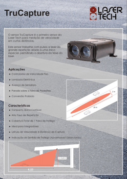
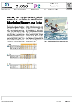
Strainoptics Laser GASP®
Quick-Start Guide
GUIA RÁPIDO
Note: These instructions are not meant to replace the full Strainoptics Laser GASP instruction
manual supplied with your instrument. If you are not yet familiar with the initial setup, general
operation, and maintenance requirements of the Laser GASP, or if questions arise, please refer
to the complete manual for further details.
Nota: Estas instruções têm o objetivo de substituir o manual completo de instrução do
Strainoptics Laser Gasp fornecido com o seu instrumento. Se você não esta familiarizado com o
ajuste inicial, operação geral e manutenções necessárias para o Laser GASP, ou se surgem
perguntas/dúvidas, favor verificar o manual completo.
CUIDADO: PARA EVITAR DANOS AOS OLHOS, NÃO OLHAR DIRETAMENTE PARA A LUZ DO
LASER
K. Prismas
B. Cabeçote de Entrada
D. Cabeçote de Saída
I. Prolongador do Seletor
F. Cabeçote de entrada
inclinado – botão de ajuste
Indicador J. Vernier
H. Conjunto do Compensador
(Cunha)
A. Pacote de Bateria
E. Travamento principal do cabeçote de
entrada
C. 06 cabeças de parafusos
G. Pivô de Nivelamento do
Espelho (não exibido)
1. Place your glass sample and the Laser GASP on a clean, flat, and level surface with the
TIN SIDE up. To verify that you are measuring on the tin side of the glass, use a UV lamp
(available from Strainoptics, part #UV-STI-4).
Coloque sua amostra de vidro e o Laser GASP sobre uma superfície nivelada, limpa e
plana com o LADO ESTANHO para cima. Para verificar se você esta analisando o lado
estanho, use a lâmpada UV (disponível com o código UV-STI-4)
2. With the power switch on the battery pack (A) in the OFF position, insert the small silver
plug attached to the Input Head (B) into the small jack on the side of the battery pack.
Turn the power switch to the ON position. Verify that the laser light is on by lifting the
instrument slightly and noticing the red reflection on the surface of the glass or table.
Note: When the instrument is not in use, always turn the power switch OFF to save
battery power.
Com a chave de força do pacote de bateria (A) na posição OFF, insira o pequeno
conector prata fixado no cabeçote de entrada (B) na pequena jaqueta na lateral do
pacote de bateria. Coloque a chave de força na posição ON. Verifique se a luz do laser
esta ligada, levantando o instrumento cuidadosamente e observando se há uma reflexão
vermelha na superfície do vidro ou mesa. Nota: Quando o instrumento não esta em uso,
sempre coloque a chave na posição OFF para salvar bateria.
3. To minimize the possibility of damage to the Laser GASP’s prisms, be sure that the point
of
measurement is free of abrasives. Place a few drops of index matching fluid
(approximately 1/2-inch diameter) on the sample where the measurement is to take
place. Carefully lower the Laser GASP body onto the glass so that the pool of fluid
completely covers the prism faces on the bottom of the instrument. This is the area
directly underneath the six screwheads (C) located on the side of the Laser GASP body.
Move the instrument back and forth (lengthwise) slightly to distribute the fluid evenly over
the prism faces. Both prisms should have good contact with the glass.
Para minimizar a possibilidade de danos aos prismas do Laser GASP, tenha certeza que
o ponto de medição esteja livre de abrasivos. Coloque algumas gotas do fluído de teste
(aproximadamente 12mm de diâmetro) sobre a amostra onde a medição deve ser feita.
Cuidadosamente abaixe o corpo do Laser GASP sobre o vidro, então a piscina de fluído
cobrirá as faces dos prismas embaixo do instrumento. Esta é a área que estará embaixo
dos 06 cabeças de parafusos (C) localizados na lateral do corpo do Laser GASP. Mova o
instrumento par trás e para frente (longitudinalmente) ligeiramente para distribuir o fluído
de maneira uniforme sobre a superfície do prisma. Ambos os prismas devem ter bom
contato com o vidro.
4. For the best viewing image, the intensity of the laser light passing through the sample
should be maximized. For reading accuracy, the light path must be directed to travel
through the stress layer near the surface of the glass. If these adjustments have not been
made, follow these instructions using the practice sample supplied with your Laser
GASP:
Para uma melhor visualização da imagem, a intensidade da luz do laser passando
através da amostra deve ser maximizada. Para a acuracidade da leitura, o trajeto da luz
deve ser direcionado para viajar através da camada de stress perto da superfície do
vidro. Se estes ajustes não foram feios, seguir as instruções abaixo usnaod a ampstra
fornecida com o equipamento.
To maximize light intensity – Position the practice sample lengthwise on the table,
perpendicular to your body so that you can look into the sample from its edge. Place the
Laser GASP at a midpoint on the surface of the sample, with its output head (D) facing
you. With your eyes level to the sample, you should be able to see the laser light exiting
the glass edge. Loosen the input head locking knob (E) and, while observing the light
intensity, slowly move the input head (B) backward or forward until maximum light
intensity is seen. Tighten the input head locking knob.
Para maximizar a intensidade da luz – Posicione a amostra de prática (fornecida co o
equipamento) longitudinalmente sobre a mesa, perpendicular ao seu corpo, então você
poderá olhar dentro da amostra a partir da borda. Coloque o Laser GASP no meio do
ponto a ser medido na superfície da amostra, com o cabeçote de saída (D) faceando
você. Com seus olhos nivelados com a amostra, você deve estar disponível para ver a luz
do laser saindo pela borda do vidro. Desaperte o botão do cabeçote de entrada (E) e
enquanto observando a intensidade da luz, mova lentamente o cabeçote de entrada (B)
para frete e para trás ate maximizar a intensidade da luz seja visível. Aperte o botão do
cabeçote de entrada.
To optimize the laser light path – Slowly turn the input head tilt-adjust knob (F) while
observing the laser light exiting the sample at the edge. Adjust the light path until it is as
close to the top surface of the sample as possible, without losing light intensity.
Para otimizar o trajeto da luz do laser – gire lentamente o cabeçote de
entrada inclinado – ajustando o botão (F) enquanto observa a luz do laser
saindo pela bord da amostra. Ajuste o trajeto da luz até que ela esteja o
mais próximo possível no topo da superfície da amostra, sem perder a
intensidade da luz.
5. While looking down into the eyepiece, slowly adjust the mirror pivot lever (G) until a red
laser light or alternating red and black lines (known as fringes) are visible. Slowly rotate
the tilt-adjust knob (F) until the lines are well defined. If the image appears cut off at
either end, slowly slide the wedge compensator assembly (H) left or right to center the
image and maximize the viewing area.
Enquanto observa a amostra pela lente, ajuste lentamente o pivô nivelador do espelho
(G) até que a luz vermelha do laser ou as linhas vermelhas e pretas alternadas
(conhecidas como franjas) são visíveis. Lentamente gire o botão de ajuste da inclinação
(F) até que as linhas mostradas sejam bem definidas. Se as imagens aparecerem
cortadas em ambos os lados, deslize lentamente a cunha do conjunto do compensador
(H) para esquerda ou direita para o centro da imagem e maximize a área de
visualização.
Linhas do retículo
(selecione uma para trabalhar)
Franjas
Retíclo não esta
paralelo às
franjas
Espaço Negativo
Colocando o retículo
directamente sobre as
franjas pretas não será
fornecido o melhor o
melhor indicador de
paralelismo
Colocando as linhas do retículo “muito perto” das
bordas de uma franja criada cria uma tira de luz
entre os dois. A tira de luz (espaço negativo) é
facilmente balanceado uniformemente ao longo da
franja. Isto dará uma maior consistência na
indicação do paralelismo.
6. Once a good image is obtained, rotate the protractor dial (I) until the reticle lines in the
eyepiece are aligned parallel to the black fringe lines in the image. NOTE: The reticle
lines do not have to be placed over the fringe lines. To ensure parallelism, position the
reticle lines slightly offset from the fringe lines and use the “negative space” between the
fringe line and the reticle lines to arrive at the proper position (refer to illustration). Note
the angle of the protractor scale at the zero point of the vernier indicator (J).
Uma vez que uma boa imagem tenha sido obtida, gire a escala do prolongador (I) até
que as linhas do retículo na lente estejam paralelas as linhas pretas na imagem. Note:
As linhas reticulares não devem ser colocadas sobre as linhas das franjas. Para
assegurar paralelismo, posicione as linhas do retículo deslocadas ligeiramente das
franjas e use o “espaço negativo” entre as linhas das franjas e as linhas do retículo para
chegar na posição adequada ( ver a ilustração). Registrar o ângulo da escala do
prolongador no ponto zero do indicador vernier (J).
7. To convert the angle reading to a stress value, use the angle vs. stress table that came
with your instrument. This conversion chart was calibrated specifically for your Laser
GASP and is not interchangeable with any other instrument.
Para converter o ângulo de leitura, use a tabela de ângulo x stress que é fornecida junto
com o instrumento. Este gráfico de conversão foi calibrado especialmente para o seu
Laser GASP e não é intercambiável com outro instrumento.
8. If you are having difficulty using the Laser GASP, and cannot solve the problem by
referring to the complete instruction manual, please contact a Strainoptics Technical
Support Representative.
Se você estiver tendo dificuldades para usar o Laser GASP e não pode solucionar o
problema usando o manual completo, favor contatar Suporte Técnico da Strainoptics.
Baixar