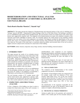
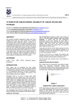
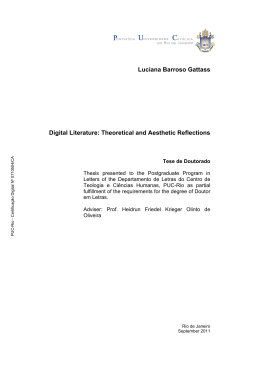
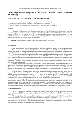
Fédération Internationale du Béton
Proceedings of the 2nd International Congress
June 5-8, 2006 – Naples, Italy
ID 1-17
Session 1 – Large projects and innovative structures
The New Braga Municipal Stadium, Braga, Portugal
Furtado, R., Quinaz, C., Bastos, R.
AFAssociados - Projectos de Engenharia, SA. Porto, Portugal
Introduction
A dramatic engineering and
architectural state-of-the-art
stadium was built to receive
EURO2004 championship.
The site was a hill with a
very good granite quarry on
its top and the Client wanted
a 30.000 seat Stadium. The
view of the valley was
beautiful:
The
Architect
imagined one stadium with
only two stands - one would
be carved in the rock as in a
Greek Theatre; the other
Fig. 1. General View of the Stadium – East Stand
one would stand up from the
ground (Fig. 1).
The rock excavation and the roof were the big challenges for the team. The roof should go along with the
idea of integrating the Stadium in the environment. It should be as light and clean as possible. Arches,
trusses, poles, cables and membranes wouldn’t fit in the concept.
A suspended roof came up as the natural solution. The rock was there to anchor the cables and the reaction
of the roof in the cantilevered stand would “help” stabilising it. The doubt was the dynamic behaviour of a
202m span roof and the fact that the roof would have to be built 50m high.
Research on similar structures and preliminary calculations showed the feasibility of the solution and that an
appropriate geometry and slab weight could lead to a desirable balance of moments in the foundation for
permanent combinations of loads.
A structure of parallel “blades” would provide the required stiffness for the stand and
would allow to fit all the stairs, concourses, bars, etc, in the middle.
Acting on the safe side, we were committed to the idea of a continuous roof. This
solution, however, could not allow enough light for the pitch. The division of the roof in
two had then to be faced and tested.
The initial studies showed that the solution with two separate roofs was possible but
confirmed the need to develop the analysis of the dynamic interaction between the roof
and the wind. The calculation of the main forces on the stands and on the foundations
also showed the feasibility of the solution. Buildability was studied and a precast plank
slab proved to be a feasible solution for the construction of the roof (Dulles airport in
Washington had been built that way 40 years before). Cost estimates revealed that it
could fit the budget. The concept was then fixed and detail design began.
Fig. 2. Architect’s sketches
Proceedings of the 2nd
Congress
Session 1
June 5-8, 2006 – Naples, Italy
Large projects and innovative structures
Architecture and Engineering
The program was new to the whole team. With no preconceived ideas, we started from scratch. In Souto de
Moura´s Architecture the technical needs of the construction rule the development of the design. Beyond
what results from the definition of the spaces, aesthetics results of an intense, demanding and stimulating
dialogue between the architecture and the engineering, whereby the search for solutions only ends when
both disciplines are satisfied. Clear and rigorous criteria are agreed to discipline the solutions for the technical needs of the building.
Fig. 3. West Stand (interior)
The result should be simple in form and in detail. But simplicity is only achieved through a gradual and continuous process of successive modifications that often bring up solutions that are quite different from the
original ideas.
Architects and Engineers worked together to achieve a common goal, which was not viewed as the exclusive
territory of one or the other.
GENERAL DESCRIPTION
The Braga Municipal Stadium is located in Dume, in the Braga Sports Complex which will also include a
sports pavilion and an Olympic swimming pool.
The most noticeable element of the stadium is without doubt its roof, which is
made up of pairs of full locked coil cables,
spaced 3.75m apart from each other, supporting two concrete slabs that cover the
two stands of the stadium. Its span
(202m), and the fact that the cables are
free in the central zone were its main challenges. The roof is supported on two large
beams at the top of both stands – east
and west, where the cables are anchored.
Fig. 4. Roof – general view
2
Proceedings of the 2nd
Congress
Session 1
June 5-8, 2006 – Naples, Italy
Large projects and innovative structures
The east stand is structurally made up of 50m-high walls that are “pierced” by the slabs of the different floors
of foyers of the stadium. Its longitudinal stability is guaranteed by the existing slabs under the steps of the
stands. The extremely slender walls of the east stand are only 1m thick.
Fig. 5. East Stand during construction
After the roof, the west stand is perhaps the most complex structural element, due to the diversity of the
problems it involved: the uprights anchored in the rock, the functioning of the structure with the ground, compatibility between the structural functioning of elements with very different stiffness, the laying of foundations
in unstable embankments. Among the several solutions encountered it is difficult to pick out one worthy of
special mention.
The so-called pitch is in fact the building that is hidden underneath it self. It has two floors and covers the
whole area of the pitch. It includes a car park, changing rooms and all the EURO 2004 backup services. It
did not cause particular structural difficulties apart from the control of the consequences of shrinkage and
temperature variations, which
led to the installation of bearings between the columns and
the slab for the pitch platform,
especially well integrated into
the architecture.
The excavation and stabilisation of embankments that preceded the construction of the
stadium was in itself a huge
task. In total 1,700,000 m³ of
hard rock and gravel were excavated (Fig. 5), which led to
the need to retain enormous
rock embankments, in which,
unfortunately, the fractures
were in an unfavourable direction. The embankment was
retained with a net of anchors
and rock bolts to guarantee its
stability.
Fig. 6. General View of the excavation
3
Proceedings of the 2nd
Congress
Session 1
June 5-8, 2006 – Naples, Italy
Large projects and innovative structures
THE ROOF
The concept was to build a set of cables suspended from the beams at the top of the uprights, supporting the
two independent concrete slabs that covered each stand.
The geometry selected for the roof resulted from a compromise between the aim of the architect (extremely
subtle inverted arch) and the value of the force applied on the structure by the horizontal component of the
cable forces.
The selection of the kind of cable was also extremely important as it would influence the definition of the
shape and technological characteristics of the roof. Two options were possible: full locked coil cables and
parallel-wire strand cables. After studying the different characteristics of the two solutions in terms of durability, anchoring devices and dimensioning, full locked coil cables were selected, which led to smaller sections.
In the tender phase, given the vital role of the “specific” technology of each cable manufacturer, it was decided that for the cables system a Design/Build contract should be put in place, where the Contractor was
allowed to propose changes to the original design developed by AFAssociados. Responsibility for the roof
design was therefore shared by the AFAssociados project team and the Contractor (together with the manufacturer of the cables – Tensoteci).
As well as standardising the concrete slab height along the roof, the only modification worthy of mention from
the initial project to the one that became the tender winner, consisted in the grouping of the cables in pairs,
with 3.75 m spacing between each pair, two times the initially planned 1.875 m.
Fig. 7. Roof cables
The suspended roofs gave always rise to special challenges for structural engineers, caused mainly by the
wind action and the construction process.
To study the behaviour of this roof all the customary project procedures have to be rethought starting with
the essentials, from establishing the values of the actions to be considered to the forecasting of the response
of the structure and the possible interaction between the two. It was therefore necessary to use physical
models (tests in small-scale models) to complement the usual mathematical models (algorithms calculated
using computerised simulations) which, in this case, no matter how sophisticated, were not sufficient on their
own to simulate the behaviour of the structure, namely regarding the wind action.
Wind analysis and wind effects
A modern and automatic meteorological station had been set up in the neighbourhood of the stadium, in
Merelim, although at the date of the project it had only been functioning for thirty months.
To obtain the “description” of the design wind at the construction site for 100-year return period the data provided by the Merelim Meteorological Station were statistically processed and suitably “corrected” taking into
account the “meagre” thirty months of records.
4
Proceedings of the 2nd
Congress
Session 1
June 5-8, 2006 – Naples, Italy
Large projects and innovative structures
The extreme analysis of the anemometer data used the Leiblein method on independent gust velocities. The
analysis for mode and dispersion was done on the square of the velocities as this provides a better fit to the
Fisher Tippet type 1 distribution of extremes.
Wind Speed (m/s)
50
original
adjusted
40
30
20
0
90
180
270
360
Wind Direction (ºE of N)
Fig. 8. Design wind speeds
To calculate the effects of the surrounding topography on the average speed and on the intensity of turbulence arising from the airflow in the vicinity of the stadium, tests were undertaken in a wind tunnel on a rigid
model in scale 1:1500. This model was made by Rowan Williams Davies & Irwin Inc. (RWDI, Canada).
Fig. 9. Wind tunnel tests (scale 1:1500)
The time history of dynamic pressures at several points of the roof, caused by the design wind for each of
the directions considered, were obtained using wind tunnel tests on a rigid model at scale 1:400. The roof of
the model was monitored with pressure sensors in 200 points distributed over its upper and lower surface.
The measurements were registered automatically, obtaining the respective time series for wind in 36 different directions spaced 10 degrees apart. This physical modelling was made by Rowan Williams Davies & Irwin Inc. (RWDI, Canada).
The calculation of the response of the structure to the dynamic action of the wind described by the history of
pressures previously obtained was done in two different ways.
The first was a deterministic dynamic time history analysis, through direct integration step by step of the dynamic equilibrium equations of the structure based on a linear elastic analysis of a shell finite element model
with a geometric stiffness matrix that was assumed as constant. The geometric stiffness matrix was obtained
using the axial forces of the cables due to the permanent loads. Through this analysis the dynamic response
of the structure to the dynamic action of the wind could be calculated. The maximum displacement calculated was 47centimetres.
The second method was a probabilistic dynamic analysis using the Orthogonal Decomposition Method. This
method is based on the principle that an unsteady multivariate pressure field can be usefully simplified by
projecting it in a space generated by the eigenvectors of the covariance matrix of the original field. This
5
Proceedings of the 2nd
Congress
Session 1
June 5-8, 2006 – Naples, Italy
Large projects and innovative structures
method has two big advantages. First, the new fields (pressure modes) are mutually uncorrelated. Second,
the energy content of the complete multivariate field is usually well represented by few components in the
transformed space, allowing the representation of the effective pressure field by mean of few pressure
modes. This analysis enabled to estimate the quasi-stationary component and the resonant component of
the response of the structure in terms of stresses and deformations. These values were used in the design of
several structural elements of the roof.
The mathematical modelling based on the results of the tests in the wind tunnel with the first physical models
did not guarantee the non-occurrence of aeroelastic instability of the roof. Although it was agreed that a behaviour of this kind would be extremely unlikely, a decision was made to develop aeroelastic physical models
to be tested in a wind tunnel.
The aerodynamic stability of the initial solution was demonstrated through tests on a aeroelastic model at
scale 1:200, made by Danish Maritime Institute (DMI, Denmark). The absence of aeroelastic instability in the
final solution was proven through tests on an aeroelastic model at scale 1:70, made by Politecnico di Milano.
Both models demonstrated the aeroelastic stability of the roof, and for the design wind speed the measured
maximum deflection was almost equal to the calculated displacement.
Drainage of rainwater
The rainwater is drained off the roof in the south-east embankment direction, with one percent fall, which is
achieved by varying the length of the pairs of cables that support the roof. Two large spouts in stainless
steel, suspended from the concrete slabs channel the water to the “aqueducts”, made of duplex stainless
steel, which lead to the rainwater network and the watercourse existing at the stadium site.
The aqueducts, approximately 40 m long, of which 27 m is overhanging, are supported on the ledges of the
embankment on columns with different lengths. The dimensions of these two devices were established
through a study of the water flow, taking into account the height of the fall, limited by the foreseeable movement of the roof due to the wind action.
Fig. 10. Duplex stainless steel “aqueduct”
The construction process
The Architect wanted to see the roof as a continuous surface standing over the cables.
For predictability reasons of the roof behaviour, the slab is connected to the cables only in the normal direction allowing relative tangential movements between them. This option has many advantages concerned with
the response to thermal actions, to the shrinkage of the concrete roof slab and to the dynamic load of the
wind.
6
Proceedings of the 2nd
Congress
Session 1
June 5-8, 2006 – Naples, Italy
Large projects and innovative structures
Fig. 11. Roof detail
The construction sequence of stress-ribbon bridges and the Dulles airport building in Washington gave us
the direction – precast planks sliding over the cables with a minimum layer of concrete pouring to minimize
the problems that different deflections would generate.
The reinforced concrete slab is 240millimetres thick, having arrived at this value by balancing the need for a
stabilising mass while minimising its weight. The prefabricated elements were assembled over the cables, on
top of the stands. Each new piece is linked to the previous piece with bolts and the pieces were slid along
the cables using gravity. When all the elements were in position the transversal and longitudinal joints between the panels were concreted.
Fig. 12. Roof during construction
Control of geometry and monitoring
The behaviour of the structural elements of the stadium during assembly of the roof was monitored using the
information collected by the instrumentation system installed, namely: load cells in the roof cables; “internal”
instrumentation of the concrete structure (strain gauges, tiltmeters and thermometers in the uprights of the
East Stand); instrumentation of the rock massifs and foundations; load cells in the ground anchors, in-place
inclinometers.
The “phase by phase” response monitoring of the structure during assembly of the roof as well as its “mechanical interpretation” guaranteed that there would be no “surprises” in the final geometry intended for the
system of cables that give this roof its unique form.
7
Proceedings of the 2nd
Congress
Session 1
June 5-8, 2006 – Naples, Italy
Large projects and innovative structures
Fig. 13. Roof cables load cells
Presently, in addition to the static instrumentation sensors already mentioned (both in the concrete structure
and in the rock massifs) dynamic monitoring is also installed, made up of 6 triaxial accelerometers placed on
the points of highest amplitude of vibration of the roof and by cells measuring the wind pressure at various
points on the underside and top of the roof covers.
THE EAST STAND
The stand is supported on sixteen vertical blades 1 metre thick, beginning at level +87.80 and reaching level
+142.85. The hydraulic and electrical infrastructures are placed inside the uprights and the slabs, from the
level of the foundation to the level of the roof.
Fig. 14. East Stand during construction
The East Stand has no structural joints. Therefore the set of the 16 uprights with the slabs of the floors and
the stands stabilise the structure of this stand in relation to both vertical and horizontal actions.
From the beginning of the design phase it was understood that a “suspended” roof between the two stands
would have its main stumbling block on the structure of the East side, where the cables are anchored more
than 50 metres above the foundation level.
The structure of this stand should therefore adjust to the geometry of the uprights in order that the result of
the combination of the gravitational actions of the stand and the high forces transmitted by the roof minimise
the imbalance of moments at the level of the foundation. In a first phase this goal was partially achieved.
With the evolution of the project and the incorporation of the functional demands of the stadium, equilibrium
at the level of the foundation was not fully achieved, leading to a considerable adjustment of the solution at
the end.
8
Proceedings of the 2nd
Congress
Session 1
June 5-8, 2006 – Naples, Italy
Large projects and innovative structures
On top of the walls there is an extremely stiff beam following the direction of the roof cables (top beam),
which guarantees the transition between the roof cables and the uprights.
Fig. 15. East Stand general view
Regarding the foundations, there are three types of geological-geotechnical strata. This heterogeneity was
especially important, and several analyses were carried out representing the global behaviour of the structure with ground-structure interaction. Taking into account the sensitiveness of the structure to the subsistence shown in the numerical models, the option was to replace the earth of lesser quality with concrete,
thus guaranteeing the whole structure is based on rock.
THE WEST STAND
The West Stand of the stadium is “carved” in a granite massif whose upper level is at the level of the square
that gives access to it. The relation between circulation zones located under the stands with the “striking”
rock embankment, characterised by irregular cuts and pronounced fractures, had to be emphasised in the
Project.
Fig. 16. West Stand – Rock anchors detail
9
Proceedings of the 2nd
Congress
Session 1
June 5-8, 2006 – Naples, Italy
Large projects and innovative structures
Taking advantage of the fact that the upper square (West) is at the same level as the roof, the horizontal
actions transmitted by the roof cables were stabilised by anchoring directly to the massif.
Fig. 17. West Stand during construction
Eighteen uprights were positioned in this transition zone, between the roof and the rock, all 1 metre thick,
which are adjusted to the irregularities of the embankment.
The steps of the stands are prefabricated and are supported on pre-stressed and reinforced concrete angled
beams, continuous along the 18 alignments in the direction of the axes of the walls.
Given the characteristics of the massif of the foundation, the foundations of the structure are of the direct
kind (footings). To support the columns and uprights in zones of fragmented massif and around the crest of
the embankments local stabilisation was undertaken using definitive anchors.
Fig. 18. Direct foundations (West Stand)
10
Proceedings of the 2nd
Congress
Session 1
June 5-8, 2006 – Naples, Italy
Large projects and innovative structures
This highly hyperstatic structure is very sensitive to settlements of supports, which led to the meticulous
control of possible settlements, not only through the calculation of the structure considering the
ground/structure interaction, but also improving the ground foundation behaviour by making it work in a more
uniform way.
The reactions of the roof and the horizontal components of the reaction of the stands determined the
dimensioning of the uprights. As this was an essential component of the global stability of the stadium, and
as the uprights were founded in zones of differing geotechnical characteristics, models had to be developed
representing the ground/structure interaction that allowed the design of the anchors to be confirmed, and the
state of permanent compression between the uprights and the rock embankment to be verified. As such, it
was possible to confirm the global equilibrium of the uprights in relation to the loads transmitted to them and
proceed with their internal dimensioning, including the foundations.
The upper level of the anchors transmits “almost directly” the majority of the horizontal load to the rock
massif. The lower level of anchors play a crucial role in correcting the direction of the upright reaction in its
foundation, channelling the resultant of forces to the interior of the massif, which is necessary, given the
fracturing of the rock under the foundation.
Fig. 19. West Stand – Balance of forces
CONCLUSIONS
Complexity and variety of technical problems involved in the design and construction of the “New Braga
Municipal Stadium” constituted a great challenge for the design team and, at the same time, it was an an
excellent opportunity to increase our know-how.
In this process we were aware of the risk that arises from constantly “pushing beyond the limits”, and
controlled it through an intensive research methodology. Risk assessments, redundancies, independent
teams studying the same problem, cross-checking results, all allowed us to gradually drop the inevitable
initial “extra safety margins”.
During the 4 years of the project planning and execution, cost and time schedules lived side-by-side with the
technical demands and aesthetic aspirations of the Project. It is rewarding to realise now that to talk about
the stadium’s structure is also to talk about its architecture, and that to explain its architecture is to tell the
story of the engineering problems it brought up and how they were overcome.
11
Proceedings of the 2nd
Congress
Session 1
June 5-8, 2006 – Naples, Italy
Large projects and innovative structures
Fig. 20. Roof drainage of rainwater detail
ACKNOWLEDGEMENTS
Owner:
Architect
Structural design:
Contractors:
Cable manufacturer:
Braga Municipality
Eduardo Souto de Moura
AFAssociados, Projectos de Engenharia, SA. Porto, Portugal – Rui Furtado,
Carlos Quinaz, Renato Bastos, Rui Oliveira, Pedro Moás, Miguel Paula Rocha
ACE / Soares da Costa, Portugal – Luís Afonso
Tensoteci – Massimo Marini, Massimo Majowiecki
12
Download