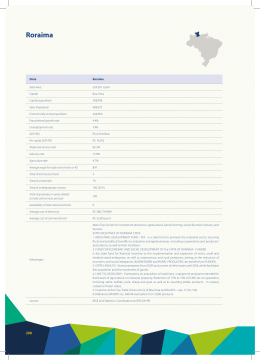
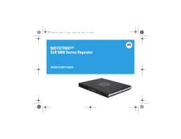
CAIXA SEPARADORA DE ÁGUA E ÓLEO
CAJA SEPARADORA DE AGUA Y ACEITE
WATER AND OIL SEPARATOR BOX
ZP5000
MANUAL DE INSTRUÇÕES
MANUAL DE INSTRUCCIONES
INSTRUCTIONS MANUAL
ENGLISH
WATER AND OIL
SEPARATOR BOX
INSTRUCTIONS MANUAL
Water and Oil Separator Box
INDEX
PREFACE....................................................................................................... 5
USED ABBREVIATIONS ........................................................................ 5
USED SYMBOLS ................................................................................... 6
INTRODUCTION ........................................................................................... 7
ZEPPINI SSAO ...................................................................................... 7
CSAO – ZP5000 .................................................................................... 9
TRANSPORTATION AND STORAGE .............................................................. 11
TRANSPORTATION AND STORAGE ..................................................... 11
CSAO – ZP5000 COMPONENTS ......................................................... 12
INSTALLATION ............................................................................................. 14
NECESSARY TOOLS AND MATERIALS ................................................ 14
INSTALLATION PROCEDURES ............................................................. 14
ANCHORAGE ................................................................................................ 24
NECESSARY MATERIALS...................................................................... 24
EXECUTION PROCEDURES ................................................................. 24
OPERATION .................................................................................................. 27
MAINTENANCE ............................................................................................ 29
ANNEX ......................................................................................................... 31
Water and Oil Separator Box
PREFACE
This manual aims to instruct the installers and operators of the ZP5000 Water
and Oil Separator Box about the best installation and handling practices of
the equipment. The rigorous accomplishment of the instructions here contained warrants a bigger durability of the equipment and a bigger easiness/reliability of its installation.
We remember that the no accomplishment of any of the instructions here
contained will annul the product warranty.
USED ABBREVIATIONS
In order to facilitate the reading of this manual, some abbreviations are used,
like as:
CSAO – ZP5000
SSAO
MPF
MIE
MCO
Water and Oil Separator Box ZP5000
Water and Oil Separator System
Pre-filter Module
Effluent Inspection Module
Oil Collection Module
5
Preface
USED SYMBOLS
Along this manual, you will found some symbols. Their meanings are described bellow:
HINT
This symbol indicates that the following instructions can and
will facilitates the installation/operation of the equipment.
!
WARNING
!
DANGER
This symbol indicates that the following instructions are of
extreme importance for the good operation of the equipment. The no accomplishment of these instructions will
result on bad operation of the equipment at short or long
term and can, inclusive, to culminate on contamination.
This symbol indicates that the following instructions are of
extreme importance for the security of the involved people
and of the installation and/or operation of the equipment.
Do you have some doubt? Do you have some problem, critique or
suggestion?
If along the reading of this manual or of the equipment installation or
operation you have some doubt, suggestion or critique, feel free for to
contact us!
(55 11) 4393-3600
Estrada Particular Sadae Takagi, nº 673, Bairro Cooperativa
São Bernardo do Campo / São Paulo / Brasil
CEP 09852-070
Att. Technical Assistance
We will have great pleasure on attending you!
6
Water and Oil Separator Box
INTRODUCTION
Nowadays, many commercial and industrial operations generate oily effluents. These effluents can generate environmental contaminations and therefore needs of previous treatment. The CSAO – ZP5000 is an equipment
designed for to treat water resultant of this type of process before to be thrown
on the sewerage system or collected, according the in force legislation, thus
preserving the environment.
This equipment is able for to separate oily products free from served water,
allowing the output of the effluents with concentration of up to 20 mg/l of oils and
greases. Each CSAO – ZP5000 can treat up to 5000 liters of water per hour.
ZEPPINI SSAO
Although this manual treats only the CSAO –ZP5000, it is important to understand that it is part of a bigger system called “Zeppini Water and Oil
Separation System” (SSAO). The more complete is the system, the bigger
will be its efficiency.
The Zeppini water and oil separator system, is composed by the following
equipments: Affluent Collectors, Inspection Box with Filter, Pre-filter
Module (MPF), CSAO – ZP5000, Effluents Inspection Module (MIE) and Oil
Collection Module (MCO).
The served waters are, on the track operations, collected by the Affluent
Collectors (Track Grooves) and after passing by the Inspection Box with Filter
(where the debris like leaves and plastic bags are retained), it are thrown on
the Pre-filter Module for the removal of the solid sediments like earth and sand.
After this, it are thrown on the CSAO – ZP5000 that will separate the water and
the oil. The oil is directed toward the MCO and the treated water pass by
the MIE for possible collection for analysis of the effluents and it follows for the
sewerage or collection according to the in force legislation.
7
Introduction
For the good operation of the system it is necessary to dimension correctly the
served waters flow and to warrant the no emulsification (undue usage of
detergents with high concentrations, solvents, etc.) and whirling (purge of
pressure vases, etc.) of the served waters flow. On commercial and industrial
facilities that has areas for refueling and washing vehicles or parts, it is recommended to have at least one independent CSAO for each area.
MPF
CSAO
MIE
MCO
Swater and Oil Separation System (SSAO) – Zeppini
The effluents treated by the CSAO must be frequently
monitored. It is important to foresee on the system
installation, one collection point of the effluents in order to
facilitate this control.
8
Water and Oil Separator Box
CSAO – ZP5000
The CSAO is composed by two stages, that is:
Reaching the CSAO, the contaminated water is conducted to the first compartment (first stage). On this compartment there is a deflector that has the function
of to cause the first separation between the water and the free more oils and it
retains also the solid minerals (sand, stones). Moreover, the deflector directs
evenly the water flow toward the coalescent elements.
The second stage consists on to submit the flow to a controlled dripping regime
through the coalescent elements, where the small oil drops are grouped
(coalescence phenomenon) and it goes to the water surface, forming an oily
coating.
After this phase, the oily coating is manually collected by an internal tubing
system Skimmers by where it goes until the MCO for posterior disposal
according to the in force legislation. The treated water, on its turn, follows by
the 4 in. effluents output tubing, existing on the CSAO.
PRE-FILTER
MODULE
ServedWater
Input (Rough)
CSAO – ZP5000
OIL COLLECTION
MODULE
Output of the
Water Separated
from the Oil
Oil Coating
Oil
Output
1st STAGE
(Passage by the
Sedimentation Chamber)
Deflector
Coalescent
Element
2 nd STAGE
(Passage by the
Coalescent Box)
9
Introduction
IMPORTANT
1
This system aims to separate the served waters from the free oils. Oil
portions chemically emulsified on the water will not be separated by this
system. The effluents to be treated must not contain high concentrations of
detergents and solvents.
2. The water must reach the SSAO preferring by gravity. The pumping of the
effluent toward the SSAO input can reduce the system efficiency, since the
pumping will cause a higher mixture between water and oil.
10
Water and Oil Separator Box
TRANSPORTATION AND STORAGE
The correct storage of the CSAO – ZP5000 is very important for to warrant the
equipment integrity. For to store this product follow carefully the following
instructions:
!
Store carefully the CSAO – ZP5000, preserving it from
impacts, sharpened objects and flexion.
Protect the CSAO – ZP5000 from the ultraviolet rays (UV)
keeping it stored on a protected place until the moment of
its installation.
Don't put heavy objects over the CSAO – ZP5000.
Don't remove the protective coating from the CSAO –
ZP5000 until the moment of its installation.
Transport the CSAO – ZP5000 on adequate vehicles and
protected from sharpened objects that could damage it.
When carrying the CSAO – ZP5000, take care for to don't
move it during the transport. If necessary, tie it, in such a
way for doesn't deform it.
When transporting the CSAO – ZP5000 manually or with the
aid of machines, avoid impacts that could compromise its
structures.
!
If necessary to stack the CSAO – ZP5000, do it carefully.
Equipments bad stacked can slip and to cause personal
injuries or product damages.
11
Transportation and Storage
CSAO – ZP5000 COMPONENTS
4
5
6
2
1
3
7
– Oil Collector Line Connections ...........................................
– Ø4 in. Effluent Output Line Connection ..............................
– Coalescent Element ..........................................................
– Case Cover ........................................................................
– Ø1 in. Skimmers Assembly ...............................................
– Ø4 in. Affluent Input Line Connection ..............................
– Case ..................................................................................
12
1 ass.
1 ass.
3 parts
2 parts
2 parts
1 ass.
1 part
Water and Oil Separator Box
8
7
6
9
5
4
3
2
1
Details of the Oil Collector Line Connections
– Fixed Flange .....................................................................
– Sealing Ring .....................................................................
– Flange (nut) .......................................................................
– Adapter – thread ...............................................................
1 part
1 part
1 part
1 part
Details of the Affluent Input Line and Effluents Output
Connections
– Ø4 in. Sealing Flange ........................................................
– Ø4 in. Sealing Ring............................................................
– Ø4 in. Tightness Nut .........................................................
– Ø4 in. Elbow ......................................................................
– Ø4 in. Prolonging Tube ......................................................
!
1 part
1 part
1 part
1 part
1 part
At the moment of the reception, check if all the materials
were sent on the correct quantity and if it doesn't presents
damages or defects. Reject the materials supplied out of
the manufacturer specifications!
13
Installation
INSTALLATION
NECESSARY TOOLS AND MATERIALS
For to install the CSAO – ZP5000 it's necessary at least the usage of the
following tools and materials as described below:
1.
2.
3.
4.
5.
6.
7.
8.
Hack-saw frame
Saw for plastic material (PVC)
Adhesive for plastic tubes (PVC)
Sandpaper for plastics (PVC)
Spade
Hoe
Medium sand (according to the pit opening)
Type 1 stone
INSTALLATION PROCEDURE
The CSAO – ZP5000 installation is divided on 5 main phases, as follows:
1st
2nd
3rd
4th
5th
Phase –
Phase –
Phase –
Phase –
Phase –
!
14
Box Preparation
Positioning of the CSAO Case
Box Grounding/Filling
Tubing Installation
Previous Operation
Observe the procedures and security warnings described
along of the installation instructions.
Water and Oil Separator Box
1st Phase – Box Preparation
Step 1
Prepare a pit with rectangular shape and such dimensions that the distances between each one of the box lateral walls is at least of .30 m.
15
Installation
Step 2
The pit depth must be such that, after to add a .20 m sand layer (as described on the Step 4). The box upper cover must remain at a distance of
.30 m to .70 m from the finished floor in order to allow its operation and
maintenance. For the pit depth adjustment it must be considered a fall
between the served waters gutters and the box entry of at least 2% related
to its distance (L), according to the figure below. On the cases where this
dimension can't be accomplished, please contact the manufacturer..
L
2% x L
It's recommended to install the CSAO – ZP5000 on a place
of easy access for operation and maintenance and near to
the output toward the sewerage or collection place.
!
16
During the pit preparation and while it remains open, isolate
it with cones and striped tape for to avoid the fall of peoples
and vehicles.
Water and Oil Separator Box
Step 3
Remove the earth removed from the place for an area away from the pit.
!
It's important to use adequate material for filling the pit
around the CSAO – ZP5000.The local earth must be discarded and not used with this purpose.
Step 4
At the bottom of the pit, create a layer of gross sand with depth of .20 m for
the CSAO – ZP5000 deposition, considering an extra filling of sand on the
concavity existing between the two portions of the box. Compact it hydraulically (the depth of .20 m must be the layer final measure, after the compactness). Refer the figure bellow.
1st Sand
Layer
This space must be
completely filled.
!
On the cases where the CSAO is installed on the following
conditions: masonry pit not stanch, absence of track over
the box or the elevated groundwater, follow the anchorage
procedures before to go on with the installation according
to the instructions of the“ANCHORAGE”chapter, page 24.
17
Installation
2nd Phase – Case Positioning
Step 1
Position the CSAO – ZP5000 in order to keep an even lateral distance of at
least .3 m.
!
18
The box case must be always leveled. Inclines for any
extremity will cause bad operation of the system.
Water and Oil Separator Box
3rd Phase – Pit Grounding/Filling
!
Observe attentively the prescriptions of this manual about
the pit grounding/filling in order to don't compromise the
CSAO – ZP5000 structure.
Step 1
Put clean water on the interior of the CSAO up to a height of .3 m.
Step 2
Make a layer of .2 m of medium sand evenly distributed around the box.
Step 3
Compact hydraulically the sand layer put on the Step 2.
Step 4
Repeat sequentially the Steps 1, 2 and 3 up to reach the CSAO input and
output connections.
Step 5
th
Install the tubing according to the 4 Phase and afterwards finalize the pit
grounding/filling procedure until the complete tubing coverage.
Step 6
After the last sand layer, for a best finishing, put a type 1 stone layer around
the CSAO up to the access cover level.
!
Don't compact mechanically the earth put over the pit, as
this can damage the CSAO – ZP5000.
19
Installation
Type 1 Stone
6 thSand
Layer
5 th Sand
Layer
4 th Sand
Layer
3 rd Sand
Layer
2 nd Sand
Layer
1rd Sand
Layer
This space must be
completely filled with
the 1st sand layer.
If the height between the CSAO covers and the sidewalk
chamber cover is superior to the sidewalk chamber shroud
height, make at the tip perimeter, a masonry wall for to close
this space, being the height of this masonry variable
according to the CSAO installation depth.
20
Water and Oil Separator Box
!
The CSAO must be installed under a sidewalk layer, since
this equipment isn't designed for to support any type of
traffic.
The equipment can't remain exposed to the sunrays for
long time, with the risk of to compromise the resistance of
the material used for its manufacturing, could still, be
damaged during its installation or operation.
If the compactness procedure isn't followed (3rd Step), there
is the risk of collapsing or crack of the CSAO – ZP5000.
Isn't recommended the usage of mechanical compacters,
due the risk of to damage the CSAO.
After the end of the installation phase, make a general
cleaning of the entire system, removing any remaining
debris.
21
Installation
4th Stage – Tubing Installation
Step 1
Clean the ends of the PVC tubes that will be connected to the CSAO in
order to remove all the dirty and oiliness existing. For to provide an efficient
connection, apply an even layer of plastic tube adhesive on the tubing
ends.
Step 2
On the CSAO affluent input connection, connect the 4 in. PVC tube
coming from the MPF, following the connection instructions described on
the Step 1.
Step 3
On the CSAO effluents output connection, connect the 4 in. PVC tube, and
the other tube end should be connected to the MIE and afterwards it should
follow toward the sewerage or collection, following the connection instructions described on the Step 1.
Step 4
On the CSAO oil output connection, connect the 1 in. PVC tube, and the
other tube end should be connected to the MCO, following the connection
instructions described on the Step 1.
22
Water and Oil Separator Box
5th Phase – Previous Operation
Step 1
Make a complete cleaning on the entire system removing any debris after the
end of the SSAO complete installation.
Step 2
Fill the CSAO with clean water.
Step 3
Lift the (Skimmers) at 90° related to the oil output connection and remain on
this position until the draining operation.
Step 4
Liberate the water served flow for the beginning of the SSAO operation..
WARNINGS
Defects caused to the equipment due installation errors will not be
covered by the product warranty.
If some abnormality on the equipment is detected, contact Zeppini
before the product installation..
23
Anchorage
ANCHORAGE
The CSAO anchorage procedure is used when the equipment is installed
inside of masonry pit not stanch, there isn't track over the equipment or when
it's installed on locals that have elevated groundwater, for to warrant the
equipment stability on the ground..
NECESSARY MATERIALS
For to make the CSAO – ZP5000 anchorage is necessary at least the usage of
the following materials, as described bellow:
1.
2.
3.
4.
ConcretE - 0,12 m³.
6 moulds for the anchors manufacture (buckets or cans of 12 liters)
6 portions of 20 cm of iron bar
Chain inserted on polyethylene circular tube of 1 in. or polyester tape
of appropriate width with hooks on the extremities.
EXECUTION PROCEDURE
The anchored CSAO – ZP5000 installation is divided on 2 main phases, as
follows:
1st Phase – Anchor preparation
2nd Phase – Anchored system installation
24
Water and Oil Separator Box
1st Phase – Anchor preparation
Step 1
Bent the portions of iron bar on the omega shape “?”.
Step 2
Fulfill the 12 liters moulds with concrete.
Step 3
Insert the bent iron bars on the superior portion of the moulds with concrete
still fresh in order to form the anchors hooks where it will be fixed the belt.
Step 4
Wait the concrete cure.
2nd Phase – Instalación del sistema ancladoa
Consider that the following steps must be executed after the Phase 1 of the
Installation Procedures, Chapter “ INSTALLATION” on the page 15.
Step 1
Increase the pit depth in .3 m on the lateral portion between the pit wall and
the box, according to the figure on the page 26.
Step 2
Position the anchors on the pit bottom in order to align the fixation hooks for
the coupling of the polyester belt.
Step 3
Cover the anchors with sand and made the compactness, leaving visible
the hooks.
Step 4
Follow the Phase 2, Chapter “INSTALLATION” on the page 18.
Step 5
Fixate the belts on the anchors hooks by the extremities.
25
Anchorage
Step 6
Tension the belts through the turnbuckles on the hooks, two by two,
according to the figure bellow.
Step 7
Follows the installation from the Phase 3, Chapter “ INSTALLATION” on
the page 19.
26
Water and Oil Separator Box
OPERATION
The CSAO – ZP5000 operation is summarized on the removal of the separated
oil, what must be done according the following sequence:
Step 1
Position the (skimmer) oil collector existing on the first portion approximately at 1.0 to 2.0 cm bellow the water level.
Step 2
Open partially the cock existing on the oil collect tubing conducting the oil
through the collector recipient.
Step 3
Close the cock existing on the oil collect tubing as soon as you observe the
beginning of water exit.
Step 4
Return the oil collector of the first portion to its original position.
Step 5
Position the oil collector (skimmer) of the second portion approximately at
1.0 to 2.0 cm bellow the water level.
Step 6
Open partially the cock existing on the oil collect tubing conducting the oil
through the collector recipient.
Step 7
Close the cock existing on the oil output tubing as soon as you observe the
beginning of the water exit.
Step 8
Remove the oil contained on the MCO through the suction pump and
discard it according to the in force legislation.
27
Operation
!
For to avoid the entry of water on the MCO, upon the end of
each process, keep the skimmers at 90° related to the CSAO
– ZP5000 oil output connection until the next draining
operation.
Keep the CSAO covers always set on the case, avoiding the
entry on the box of the water coming from the track, causing
spilling and possible ground contamination.
The frequency of the CSAO operation for the separated oil
removal will be defined according to the oil quantity generated by the facility. It's recommended, on the beginning, to
check daily the water level, or still at each track washing.
The oil removal could be done during the CSAO – ZP5000
normal operation.
28
Water and Oil Separator Box
MAINTENANCE
The CSAO – ZP5000 maintenance consists on the equipment internal
components cleaning observing the following sequence.
Step 1
Block up the served water flow on the CSAO input.
Step 2
Remove the liquids and debris contained inside the box and stores it on
appropriated stanch recipients.
Step 3
Identify the position of the coalescent elements on the box, in order for to
keep the original position after the maintenance.
Step 4
Remove the coalescent elements pulling it by the eyelets.
Step 5
Remove and discard the solid minerals (sand and stone) accumulated
inside the CSAO according to the in force legislation.
Step 6
Wash the coalescent elements with jet of water on a place that contributes
after to the CSAO.
Step 7
Reassemble the coalescent elements on the CSAO on the positions
identified early, according to the Step 3, using eyelets.
Step 8
Fill the CSAO with clean water up to the operating system (at the level of the
effluents output connection).
Step 9
Return the served water flow toward the CSAO.
Step 10
Through the collection gutters, return carefully the liquids and residues
stored early on the Step 2.
29
Maintenance
The CSAO – ZP5000 maintenance frequency will be defined
according to the residues quantity received by SSAO
system. We recommend realize initially this operation at
least at each 2 months.
The CSAO – ZP5000 maintenance must be done on periods
without the contribution of the served waters.
!
30
Never make the coalescent elements cleaning out of the
contribution area of the CSAO.
The liquids and residues coming from the CSAO cleaning
must be packed on appropriated recipients for posterior
disposal according to the in force legislation.
Water and Oil Separator Box
ANNEX
31
Rev.: 01 - Nov.13
Download