NLR-TP-2002-170
Free Flight with Airborne Separation Assurance
An executive summary of: NLR-TP-2001-313
"Designing for Safety: the Free Flight Air Traffic
Management concept"
J.M. Hoekstra
Nationaal Lucht- en Ruimtevaartlaboratorium
National Aerospace Laboratory NLR
NLR-TP-2002-170
Free Flight with Airborne Separation Assurance
An executive summary of: NLR-TP-2001-313
"Designing for Safety: the Free Flight Air Traffic
Management concept"
J.M. Hoekstra
This report may be cited on condition that full credit is given to NLR and the author.
Customer:
Working Plan number:
Owner:
Division:
Distribution:
Classification title:
National Aerospace Laboratory NLR
V.1.C.2
National Aerospace Laboratory NLR
Flight
Unlimited
Unclassified
June 2002
-3NLR-TP-2002-170
Summary
The Air Traffic Management System, as it is used today, is a centrally organised system. One
controller, sometimes assisted by a planner, is responsible for maintaining the separation
between all aircraft in his/her sector. Pilots merely follow the directions received from the
controller and have no active role in the separation assurance. To maintain an orderly traffic
pattern, airways are used to structure the traffic flow and flight levels are used as layers to
separate aircraft. This often inhibits a more optimal direct route at the optimal altitude. The need
for maintaining situational awareness also limits the number of aircraft a controller can handle.
This is a limiting factor for airspace capacity and contributes to delays.
The study described in this report investigates a revolutionary alternative for this system, called
the Free Flight concept. In Free Flight Airspace, aircraft fly their own preferred route at their
preferred altitude. They only need to deviate from this route if it conflicts with the route of
another aircraft. The aircraft transmit their position via a data link. These data are presented on
the traffic display in the cockpit. Maintaining separation now becomes the responsibility of the
cockpit crew assisted by an Airborne Separation Assurance System (ASAS) that alerts and
advises the crew.
When this study started in 1996 the area of Free Flight was practically unexplored. In general, it
was thought to be a dangerous idea. The initial goal was to explore the human factors issues in
the cockpit, which result from moving the separation task to the cockpit. However, since hardly
any Free Flight research was available to build upon, the study first had to incorporate designing
a feasible operational concept. The operational concept describes in what way the Free Flight
concept should be implemented. What is the role of the pilot? What is the role of the systems?
What procedures should be used? What should be the rules-of-the-sky? Consequently, the study
became broader and investigated the feasibility of the operational concept based on the Free
Flight idea.
In addition to literature surveys and analysis, two experimental methods have been used to
investigate the feasibility: off-line traffic simulations, using a tool developed especially for this
study, called the Traffic Manager, and human-in-the-loop simulations with airline pilots in
NLR’s Research Flight Simulator.
Using the operational concept designed, several issues have been investigated: acceptability and
workload resulting from adding the separation task to the flying task and navigation task; the
effect of lack of a global picture and central co-ordination on the traffic pattern and the effect on
the capacity of a sector.
-4NLR-TP-2002-170
Evidence has been found that Free Flight is not only a promising concept for airspace with a
relatively low traffic density, but that it is also capable of handling much higher traffic densities
than today’s centrally organised ATM system. Because of this study, Free Flight has become
more acceptable to the aeronautical research community. Several other studies since then have
found results that confirm the conclusions of this study. The study also presents a direction in
which future Free Flight research and implementation efforts should be heading. The results
indicate that the introduction of Free Flight potentially offers economic, capacity and safety
benefits. The author is using these results to play an active role in the decision process that is
ongoing in several organisations.
-5NLR-TP-2002-170
Contents
Abbreviations
7
Definitions
8
1
Introduction
9
2
What is Free Flight?
10
2.1
Today’s situation: ground controlled separation
10
2.2
Tomorrow’s situation: Free Flight?
12
2.2.1
No ground based separation
12
2.2.2
Tools: ASAS & CDTI
13
2.2.3
Current Separation Minima
13
2.2.4
Direct routing horizontally and vertically
13
2.2.5
High traffic density scenarios
13
3
4
5
Airborne Separation Assurance System
14
3.1
Introduction
14
3.2
Conflict Detection
14
3.2.1
General approach
14
3.2.2
First step: How far can you get without intent?
16
3.3
Conflict Resolution
19
3.3.1
Conflict resolution algorithm
20
3.3.1.1
Force field algorithm (voltage potential)
20
3.3.1.2
Modified voltage potential (Eby method)
21
3.3.1.3
Final choice: modified voltage potential (Eby method)
22
3.4
Conflict Prevention: Predictive ASAS
23
3.4.1
What is Predictive ASAS?
23
3.4.2
What is the relation between this system and the need for intent?
24
Human Machine Interface
25
4.1
Design philosphy
25
4.2
Display
26
4.3
Aural alerts
28
Human-in-the-loop experiments
28
-6NLR-TP-2002-170
6
7
5.1
Phase I flight simulator trials
28
5.2
Phase II flight simulator trials
32
5.2.1
Concept F: Flight Level Split
33
5.2.2
Concept A: Protected Airways ATM concept
34
5.2.3
Concept M: Fully Mixed
34
Distributed systems vs. centrally controlled systems
36
6.1
Introduction
36
6.2
Robustness
36
6.3
Capacity
37
6.4
Bottleneck conflicts
37
Conclusion
40
7.1
Feasibility
40
7.2
Operational Concept
40
7.3
Capacity Benefits
40
7.4
Economic Benefits
41
7.5
Safety Benefits
41
References and Bibliography
42
(45 pages in total)
-7NLR-TP-2002-170
Abbreviations
ADS-B
Automatic Dependent Surveillance - Broadcast
ASAS
Airborne Separation Assurance System
ATC
Air traffic Control
ATM
Air Traffic Management
CDTI
Cockpit Display of Traffic Information
FAA
Federal Aviation Administration
FMS
Flight Management System
FF
Free Flight
HMI
Human Machine Interface
IAS
Indicated Air Speed
ICAO
International Civil Aviation Organisation
IFR
Instrument Flight Rules
LNAV
Lateral NAVigation mode = autopilot FMS coupled mode
NASA
National Aeronautics and Space Administration
NLR
Dutch National Aerospace Laboratory
PASAS
Predictive ASAS
RLD
Rijks Luchtvaart Dienst
RSME
Rating Scale of Mental Effort
RTCA
Radio Technical Commission for Aeronautics
TCAS
Traffic Collision Avoidance System
TIS-B
Traffic Information Service Broadcast
TLS
Target Level of Safety
TOPAZ
Traffic Organization and Perturbation AnalyZer
VFR
Visual Flight Rules
VNAV
Vertical NAVigation mode = autopilot FMS coupled mode
-8NLR-TP-2002-170
Definitions
Separation Minima
The prescribed minimum distances between two aircraft, in general
specified as combination of a horizontal minimum distance and a
vertical minimum distance
Separation Assurance The act of assuring that the separation minima will not be violated
Loss of separation
The situation where the distance between two aircraft is less than the
separation minima
Conflict
A predicted loss of separation
Conflict Detection
The act of or module for predicting conflicts
Conflict Resolution
Manoeuvring in a way that the predicted loss of separation disappears
Conflict Prevention
Avoiding manoeuvring into a conflict
Recovery Manoeuvre
The manoeuvre that resumes the original route after the conflict has
been resolved
Own ship
The own or active aircraft in discussions on conflicting pairs of
aircraft
Intruder
The other or passive aircraft in discussions on conflicting pairs of
aircraft
Lookahead time
Time that is used as prediction window for conflict detection and
resolution
Protected Zone
Area around aircraft determined by the separation minima, which
should not be intruded by other aircraft.
Alert Zone
In the RTCA concept aircraft in this area are a reason to alert the
crew. The concept in this study does not use an alert zone. It does use
a slightly bigger protected zone for the conflict detection & resolution
than the actual separation minima.
Explicit co-ordination Co-ordinate via communication how to resolve a conflict to avoid
counter-acting manoeuvres
Implicit co-ordination Use common rules to avoid counter-acting manoeuvres
Intent
The intended trajectory of an aircraft (the flight plan)
Priority Rules
Traffic rules to determine which vehicle should manoeuvre to solve
the conflict
Rules-of-the-sky
Traffic rules for air transport, analogue to rules-of-the-road
-9NLR-TP-2002-170
1
Introduction
In 1997 NLR started working on an Air Traffic Management (ATM) concept called 'Free Flight'
in co-operation with NASA and the RLD (the Dutch Civil Aviation Authority). In the Free
Flight concept, all aircraft are allowed to fly their optimal route ('direct routing') and the task of
traffic separation is moved from Air Traffic Control (ATC) to the cockpit ('airborne separation').
The concept therefore represents more than simply a new procedure or the use of a new tool. It
is a revolutionary change of a nowadays centrally controlled ATM system to a distributed
system.
The NLR study originally only focused on the human factors of airborne separation in a Free
Flight environment. Because of a lack of a detailed definition of the Free Flight concept, the
study evaluated several concepts derived from literature and designed a concept for Free Flight.
This concept has since then been studied in several simulations, using both human-in-the-loop
simulations and off-line simulations. These simulations have resulted in several adjustments of
the concept and related systems, mainly driven by human factors and safety.
The result is a robust concept that has been demonstrated in flight simulator trials to be able to
cope with extremely high traffic densities in a safe and acceptable way. When designed with the
humans in mind, the concept seems to be a rare case in which there are both financial benefits as
well as safety benefits.
The study started in 1997 and consisted of the following sub-studies in chronological order:
• Conceptual Design
• Off-line validations
• Airborne Separation Assurance System Design
• Safety Analysis
• First Flight Simulator experiment
• Economics of conflict resolution
• Avionics requirements study
• Critical conflict geometry study
• Predictive ASAS development
• Mixed Equipage procedure study
• Second Flight Simulator experiment
-10NLR-TP-2002-170
The resulting conceptual design of Free Flight (and related systems), as well as a selection of
the validating studies, will be described in the following sections. A complete overview can be
found in original document NLR TP 2001-313 "Designing for Safety: the Free Flight Air
Traffic Management Concept".
2
What is Free Flight?
2.1 Today’s situation: ground controlled separation
Currently commercial aircraft continuously fly under a set of rules called IFR (Instrument Flight
Rules). These rules allow the aircraft to fly even when the visibility is low. It also means the
flight is controlled by Air Traffic Control (ATC) from gate to gate. The complete route,
including the slot times at the airports for take-off and landing, is requested before the flight.
These data are sent out via the Aeronautical Telecommunications Network to all controllers that
will have the aircraft in their sector during the flight.
When there is a need for a route change this has to be requested during the flight and, if the
traffic and weather situation permits, the aircraft will receive a clearance for this route change.
Further, any altitude change (e.g. to climb to a higher, more economic flight level) requires a
clearance from ATC. Therefore, there is no freedom for the crew to change their route to a more
optimal route without negotiation with the ground.
Apart from the requests for a route or altitude change, there are several other procedures
requiring communication with the ground: when crossing a sector boundary, the controller of
the former sector ‘hands off’ the aircraft to the next controller. This requires a new position
and/or route report to the new controller as a confirmation or log-on to the sector. Maintaining
the separation of all traffic under his/her control is the responsibility of the controller of the
sector.
Since World War II, radar has been used to monitor the traffic situation. At first only around the
airport, but with the increasing amount of air traffic, also en-route traffic is monitored via the
radar. Aircraft today are also equipped with a transponder that broadcasts extra information to
the radar such as an identification code (squawk) and the altitude (mode C) for the air traffic
controller. The result is a complete overview of the three-dimensional traffic situation. Trailing
blips even provide an impression of the direction and magnitude of the ground speed. Using the
mode C transponder ensures an accurate vertical position estimate while the angular nature of
the radar might not provide a very accurate horizontal position estimate especially at larger
-11NLR-TP-2002-170
distances. Typical separation minima in these circumstances are 5 nautical mile horizontally and
1000 feet vertically.
In areas, where there is no radar surveillance (e.g. large areas of Africa and Asia) the procedural
separation replaces the radar-controlled separation. Procedural separation means that every
aircraft reports its position and by issuing the appropriate clearances, the separation is ensured
by ATC. The situational awareness of the controller is clearly less in this situation compared to
radar surveillance. The result is the use of larger margins and therefore less optimal flights and
also an inherently more dangerous situation.
A special form of procedural separation takes place over the ocean. Here tracks work similar to
a railway system: aircraft are positioned separated at the beginning of a track and will arrive at
the end of that same track. So route changes are inhibited over the ocean. These tracks are
changed regularly based on the weather situation and labelled for reference. The distance
between the tracks is one-degree latitude, meaning 60 nautical miles. The vertical separation
used to be 2000 ft but has recently been reduced to 1000 ft over the Atlantic Ocean due the
increased traffic density between Europe and North America. This enormous difference between
the vertical and horizontal separation is due to possible (different) navigation errors caused by
the inertial navigation system during the long flight over the ocean, while the altitude is
determined via the same reference (air pressure) ensuring a very accurate estimation of the
relative vertical position. Using satellite navigation to enhance and replace inertial navigation
might improve the relative lateral navigation and provide a way to reduce the distances between
the tracks.
Under radar coverage, traffic flows are normally structured into airways. Airways originally
consisted of routes flying from one beacon to the next one. In the old days, this was the easiest
way to navigate under IFR. Although today’s navigation equipment no longer requires flying
from one beacon to the next, the airways are still in place. One reason for this is that it structures
the traffic pattern, enabling one controller to monitor a complete sector. Possible separation
problems are limited to intersections and aircraft changing altitude or overtaking each other on
an airway. Apart from this benefit there are clearly some drawbacks as well: (1) the airways
might not be the most optimal or direct route, (2) the local traffic density is artificially increased
by concentrating the traffic on lines instead of using the full airspace, (3) flying on the same
route might inhibit flying the optimal flight level or speed as a result from the traffic
concentration on the airway.
When the traffic density is low (e.g. during the night) aircraft are often cleared for direct flights
to a waypoint further along the route.
-12NLR-TP-2002-170
The air traffic controller’s highest priority is safety. Most of the time actions are based on
preventing conflicts far before they could become imminent. For instance keeping two aircraft
that are flying on the same airway in the same direction on a different altitude (always a value
rounded to a multiple 1000 feet) even while they won’t overtake each other, ensures he/she will
not have to monitor for a possible conflict between those two aircraft. In this way, he/she is able
to keep workload at an acceptable level during high-density traffic situations. Though safe, it is
not the most optimal way of flying. When the traffic situation allows it, the controller will allow
the traffic to optimise their flight based on their requests. Airlines would prefer a more optimal
way of flying with respect of fuel and time within the safety margins. Self-optimisation might
provide a more optimal, while still safe, traffic pattern. This idea forms the basis of Free Flight.
Free Flight could also provide a more efficient airspace usage for instance over the ocean or
areas without radar coverage and maybe even in the radar controlled areas. The reason for this is
that in general (except the terminal area around airports) the separation assurance method, and
not the airspace volume itself, is the limiting factor on capacity.
2.2 Tomorrow’s situation: Free Flight?
In Free Flight, the separation task is moved to the cockpit. By using a system that broadcasts
identification and altitude but also the position, velocity and maybe even a part of the intended
route, every aircraft could use this to ensure the separation. Such a system is available: ADS-B
(Airborne Dependent Surveillance – Broadcast). The effect is that all aircraft receive the data
broadcast by all other aircraft in the area. The data of the other aircraft are processed by an onboard system and displayed on the Cockpit Display of Traffic Information (CDTI). Several
display formats are currently being developed to present the traffic situation to the crew in an
optimal way.
This set-up could potentially be used to perform airborne separation, the essential element of the
Free Flight concept. However, several design choices need to be made regarding how the
concept should be implemented.
During the conceptual design phase of this study several choices have been made that formed
the basis for the definition of Free Flight in the remainder of the study:
2.2.1
No ground based separation
Though there would likely be a lot of transition phases in which the separation responsibility
would not be completely transferred to the cockpit, a mature form of Free Flight has been
studied in this study: no ground controlled separation. The only role for the ground in this case
would be a very long term strategic one: ensuring that traffic density will not exceed the
-13NLR-TP-2002-170
capacity of airspace, exit/entry points of the Free Flight area and runways of the origin and
destination airports. This is referred to as “Traffic Flow Management” by the RTCA report on
Free Flight1. It is also referred to as autonomous aircraft, which will be able to maintain
separation even over areas without radar coverage. This Freedom of Flight would allow true
real-time self-optimisation.
2.2.2
Tools: ASAS & CDTI
Several tools will be required to assist the crew in the separation task: an Airborne Separation
Assurance System or ASAS will detect predicted loss of separation (conflict). This is often
referred to as conflict detection, though it does not actually detect conflicts but only predicts the
possibility of a conflict within a certain time-span, the so-called look-ahead time. A conflict
resolution module inside the ASAS calculates a recommended manoeuvre to avoid loss of
separation. The information of the system is presented on the CDTI integrated with the traffic
symbology.
2.2.3
Current Separation Minima
In the study, the separation minima which define a conflict have been set at today’s ATC
separation minima: 5 nautical miles and 1000 feet vertically (thought often still 2000 ft is being
used). This does not mean that these values are also be required in a Free Flight environment
but it does provide a way to compare the results of the study with today’s situation.
2.2.4
Direct routing horizontally and vertically
True self-optimisation has been applied both in the horizontal plane and in the vertical plane.
This allows direct routing but also flying at the most optimal altitude, even at values in between
the multiples of 1000 ft. Most aircraft will be climbing slowly during the cruise (cruise climb)
because the lower weight (caused by the fuel consumption) continuously increases the optimal
altitude.
2.2.5 High traffic density scenarios
The first application of Free Flight will probably be in low traffic density areas. However, offline traffic simulations in this study clearly indicated that conflicts are very rare in a direct
routing environment, in which each aircraft flies at its optimal altitude with today’s traffic
density. By using the current separation minima with today’s busy traffic over Western Europe,
under nominal conditions in the upper airspace a loss of separation would be predicted typically
once per hour per aircraft. This would not be a predicted collision but merely that one aircraft
would come closer than 5 nautical miles (9 kilometres) within the altitude of 1000 ft (300 m). In
1
RTCA Board of Directors’ Select Committee on Free Flight
-14NLR-TP-2002-170
a man-in-the-loop simulation aimed at providing human factors data, this low conflict rate is a
problem from an experimental point of view. By using artificially high traffic densities (triple
the average Western European traffic density) and an even higher conflict rate (tripled again, so
nine times per hour) the NLR team hoped to provide the crew with a challenging task that might
provide insight into some interesting cockpit human factors issues of airborne separation.
3
Airborne Separation Assurance System
3.1 Introduction
The design of the ASAS system formed a critical part of the project. Several options, with
respect to conflict detection, conflict resolution, display symbology and parameters of the
systems, have been studied in literature and by using off-line and on-line simulation. An
essential part of the study was the design of the conflict detection and conflict resolution and the
Human Machine Interface (HMI). After the first human-in-the-loop trials, it was found that a
conflict prevention module was also required. This resulted in the development of the predictive
ASAS (PASAS).
3.2 Conflict Detection
3.2.1
General approach
It could very well be that the crew is able to predict conflicts by monitoring a well designed
traffic display (CDTI) based on showing only the aircraft symbols. However, this might not be
an optimal situation because the crew also has to control the aircraft and systems. During the
climb and descent, the workload might be too high, whereas it might be too low during the
cruise phase. The process of conflict detection is also mainly one of calculation, which is a task
with which the automation might provide valuable help.
The result of the conflict detection module should be an alert to the crew as well as some
information on the conflict, such as identification of the conflicting aircraft, time to loss of
separation and other geometrical information. These data are used to display the conflict to the
pilots and to supply input to the conflict resolution module.
To predict a conflict the trajectory of the “ownship” and the surrounding traffic needs to be
predicted. There are several approaches possible depending largely on the look-ahead time. The
most important issue is which level of intent information to use (and how):
-15NLR-TP-2002-170
1. No intent (just position and extrapolate with velocity)
2. Mode control panel intent (autopilot info)
3. The next trajectory change point
4. Complete flight plan as stored in the flight management system (FMS) of the aircraft
Except for bullet 1, all other information supplies some form of future state, which could be
altered by the human crew at any time. Therefore, confirmation of this future state will become
necessary with all levels of intent except bullet 1. The future trajectory of the aircraft might not
always be the route as stored in the FMS and the selected altitude value in the mode control
panel might merely be a reminder to switch from IAS climb to Mach climb or some other
action. So using more intent information not only enhances the prediction, it also excludes a
number of predictions. Using only position and velocity information is only useful with limited
look-ahead times and depends on the route structure. In a direct route environment, this will
often match the future trajectory, in an airway-like route structure more turns might limit the
useful look-ahead time based on state information alone. An overview of some of the
advantages and drawbacks of each method is given in the table below.
Intent level
None
Mode control
panel
(autopilot)
First trajectory
change point
Route
Pro
• Simple, thus easy to
implement (retrofit)
• Transparent to the crew
• Low bandwidth
• High update rate
• No requirements to change
avionics infrastructure
• Relatively simple
compared to FMS
Con
• Will miss conflicts due to short term turning
into traffic or leaving or arriving at a level
(without extra precautions)
• Not accurate for longer look-ahead times
•
Compared to full route
limited bandwidth
requirements
•
Will be able to use long
look-ahead time
Provides an accurate
prediction in LNAV and
VNAV, which are often
used during the cruise
phase
•
•
•
•
•
•
•
•
•
•
Enhancement compared with no intent might
be limited when in LNAV or VNAV (without
extra precautions)
Will miss conflicts when not flying in LNAV
or VNAV without extra precautions
Accuracy with relation to look-ahead time
might vary depending on distance to next
trajectory change point
Only works in LNAV and VNAV mode
without extra precautions
Complex systems
Requires priority rules due to discontinuous
resolution
Hard to understand (not transparent)
Lowest update rate
Compatibility problems between different
brands of FMS
-16NLR-TP-2002-170
From the table it is clear there are some drawbacks to every method. Using extra information
adds complexity and also introduces some problems. The route information in the FMS is only
accurate when flying in the FMS controlled autopilot modes (LNAV & VNAV).
The most complex solution has the strongest advantages and disadvantages. NLR has studied
both extremes of the intent spectrum: no intent and using route intent. Initially the no intent
option has been explored. Note that in the table both approaches require ‘extra precautions’. In
case of using intent it might mean you also use the state based system as an add-on and in case
of the state based system, a system like predictive ASAS (PASAS) might seal the leak caused
by not using intent information. Both options also have their specific problems in the conflict
resolution module.
3.2.2
First step: How far can you get without intent?
As previously mentioned, the ‘no intent’ option has been explored most extensively in the
study. Adding features, which add to the complexity, should only be done when required. Using
no intent was thought to be the best way to find out how intent might be required to improve the
system. If it is possible to fly safely without exchanging intent information, this has huge
benefits (see preceding table) in terms of:
•
Low complexity
•
No negotiation required
•
Conflict alerts transparent to crew
•
No compatibility problems
•
Faster than route which requires more time to be transmitted
•
Lower risk of instability due to shorter look-ahead time
•
Implementation of ADS-B with low bandwidth (likely) will still allow realisation of
concept
To prevent the obvious missed alerts and false alarms due to turning aircraft an additional
system has been added: predictive ASAS (see PASAS section for details).
For state based conflict detection, vector calculations are sufficient. The conflict detection
algorithm in the NLR state based system contains the following steps:
1. Use smooth state data of traffic, extrapolated when necessary.
2. Skip aircraft for which a head-on closure speed is not sufficient for a conflict given the
look-ahead time
3. Calculate the interval of loss-of-separation horizontally
4. Calculate the interval of loss-of-separation vertically
-17NLR-TP-2002-170
5. Is there an overlap within the look-ahead time? If so, then store conflict together with
conflict data
6. Filter conflicts to prevent alerts due to manoeuvring aircraft
The resulting conflicts are stored in the conflict database. These data are, per conflict:
•
Time of loss of separation (intrusion time)
•
Time of closest point of approach (minimum distance time 3D)
•
Position of ownship at minimum distance point (incl. altitude)
•
Speed of ownship at minimum distance point (incl. track)
•
Identification of intruder (incl. altitude)
•
Position of intruder at minimum distance point
•
Speed of intruder at minimum distance point
The horizontal minimum distance point (closest point of approach) horizontally is calculated
using the following formula:
t min dist = −
dv ⋅ dx
dv ⋅ dv
This might not be in the vertical interval where loss of separation is. When required it is
therefore mapped on to the 3-dimensional interval of loss of separation.
Since the separation has been defined as the horizontal and vertical distance between two
aircraft, multiple-aircraft conflicts do not exist mathematically speaking. As a result of the
conflict detection algorithm they are merely a collection of two-aircraft conflicts. This is also
the way they are stored in the conflict database. The conflict resolution algorithm should be able
to cope with several conflicts at the same time.
These data are sufficient for the state-based version of the conflict resolution module in the
system. In the intent version of the conflict detection module, extra data has been added to
determine the positions on the conflicting legs of the ownship and intruder.
-18NLR-TP-2002-170
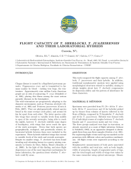
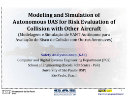
Fig. 3.1 Traffic manager
The conflict detection module has been developed and tested on a tool called the traffic
manager. The traffic manager program has been developed within this study to analyse and
simulate traffic situations of up to 400 aircraft simultaneously. This tool is able to generate
traffic controlled by pilot models, autopilot modules, flight management system and includes
performance characteristics of over 200 aircraft types. It is controlled using a graphical user
interface as shown the figure above. It is used for off-line (optionally fast-time) simulation,
scenario editing, environment simulation (for the flight simulator(s)), experiment console, data
logging and data analysis. It also hosts the ASAS systems for all simulators connected to the
traffic manager program. The program is able to interface with external consoles, ATC stations
and several flight simulators. Current developments include an internet game domain like
features to host web based experiments. The program runs on a graphical workstation but also
on a common personal computer.
Reference data from Eurocontrol and the PHARE study average Western-European traffic
densities have been used for the off-line simulations. An off-line simulation of a direct route
environment has been created with these data. One surprising result was the low conflict rate
that occurred. Using these scenarios a conflict was detected on average only once per hour
(when the aircraft were not in the terminal area of an airport). A set of critical geometries for
conflict detection and resolution have been tested and used to debug the conflict detection and
resolution system.
-19NLR-TP-2002-170
From initial trials for a look-ahead time, a value of five minutes proved to be most effective
with the state-based system. A longer look-ahead time did not add much to the effectiveness and
could potentially lead to unnecessary manoeuvring. The lower limit while maintaining an
acceptable level of passenger comfort with a horizontal manoeuvre was in the order of three
minutes for worst case: exactly head-on with today’s cruise speeds. Therefore the look-ahead
time has been set at five minutes for the remainder of the study.
3.3 Conflict Resolution
A resolution advisory module is part of the Airborne Separation Assurance System (ASAS)
system design. The conflict database and the traffic information are the input for the module.
The module calculates one or more manoeuvres which would solve the conflict(s). It could very
well be possible by designing the conflict symbology, which show all the aspects that the
resolution algorithm uses, that the actual conflict resolution might be performed by the crew.
The actual calculation of the shape or magnitude of the resolution manoeuvre does typically
involve some calculation, which is where automation is able to provide valuable help. The
actual decision of which manoeuvre to execute might involve strategies only known to the crew.
In keeping with the generally held notion of “human-centred automation”, the role of such
automation should be limited to advising, rather than actual selection and implementation of
alternative actions.
This consideration of the role of the resolution module formed the basis of the following main
requirements of the module:
• Calculate manoeuvre/route change that resolves the conflict effectively
• Resolution module should be efficient in terms of time, fuel and route
• Should allow insight in the resolution generation process via the HMI
• Preferably generate more than one resolution to allow the crew to choose the most
optimal one considering the complete situation
• Be able to handle multiple-aircraft conflicts
• Provide fail-safe or back-up options to increase the safety
• Prevent counteractive manoeuvring by two or more conflicting aircraft
• Resolution module should be fair (in terms of manoeuvre/economic costs) to the aircraft
involved
• Module should not result in unstable, catastrophic traffic patterns
-20NLR-TP-2002-170
3.3.1
Conflict resolution algorithm
Based on earlier studies and available literature, several options were considered:
1. Vertical manoeuvres (TCAS-like)
2. Genetic algorithms
3. Extended VFR rules (as developed by Eurocontrol)
4. Cross product algorithm
5. Force field algorithms (Voltage potential)
6. Modified voltage potential (Eby)
Several of these methods were implemented in the traffic manager and validated. The final
choice was a variant of an algorithm which is based on the force field or voltage potential
analogy.
3.3.1.1 Force field algorithm (voltage potential)
The voltage potential is an analogy, which compares traffic with electrically charged particles.
Suppose all aircraft would be regarded as positively charged particles and their respective
destinations as negatively charged. Summing all the repulsive forces of the traffic and the
attracting force of the destination is a way to determine a vector, which maintains separation
with other aircraft and will bring the aircraft to its destination. The figure below show a
schematic representation of this principle.
Fig. 3.2 Simplistic view of voltage potential
-21NLR-TP-2002-170
This resolution method is much too simplistic to be used in free flight. For example no
minimum separation is guaranteed and attraction to destination varies with distance to
destination. It is also quite impractical to sum the repulsive forces of all aircraft (including the
ones with which no conflict is predicted).
3.3.1.2
Modified voltage potential (Eby method)
At the Lincoln Laboratory (MIT, Massachusetts, USA) an algorithm has been developed which
retains the basic repulsion feature of the voltage potential, but has a more pragmatic approach to
solving conflicts (see figure below).
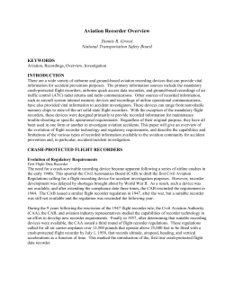
Fig. 3.3 Geometry of resolution method
This method has been slightly modified for use in the resolution module in the NLR study.
When a conflict with traffic has been detected by the conflict detection module, the resolution
module uses the predicted future position of both ownship and the obstacle aircraft (will be
called intruder) at the moment of minimum distance. The minimum distance vector is the vector
from the predicted position of the intruder to the predicted position of the own ship. The
avoidance vector is calculated as the vector starting at the future position of the ownship and
ending at the edge of the intruder's protected zone, in the direction of the minimum distance
vector. The length of the avoidance vector is the amount of intrusion of the own ship in the
intruder's protected zone and reflects the severity of our conflict. It is also the shortest way out
of the protected zone. Therefore the ownship should try to accomplish this displacement in the
time left till the conflict. Dividing the avoidance vector by the time left yields a speed vector
which should be summed to the current speed vector to determine the advised speed vector. The
result is an advised track and ground speed. Using the three-dimensional vector also yields an
-22NLR-TP-2002-170
advised vertical speed. In case of multiple conflicts within the look-ahead time, the avoidance
vectors are summed.
Each geometrical resolution method has its singularities in which the avoidance vector becomes
zero or the sign cannot be determined. Though this could be regarded as a theoretical problem,
since in reality noise will prevent these singularities from lasting very long, numerical
techniques like integer calculations or limited resolution in numbers could make it happen. This
resolution method is no exception to the rule and several provisions are made to solve the
singularities. For example, in case of an exact head-on collision course on the same altitude with
no vertical speed, both aircraft will be advised to turn right.
This resolution method assumes the intruder does not manoeuvre to avoid the conflict. This is
part of the fail safe principle of the concept. Normally the intruder will also manoeuvre. Using
the same principle will always result in an avoidance vector in the opposite direction because of
the geometry of the conflict (compare the future positions with the charged particles). Therefore
an effective co-operation is achieved without negotiation or additional communication. This
also means the initially calculated advised heading and/or speed changes will normally not be
required. As soon as the conflict disappears, the current heading, speed and/or vertical speed can
be maintained. This means both aircraft 'suffer' equally due to the conflict.
Both aircraft can choose whether they solve the conflict horizontally or vertically and they
initially calculate the resolution advisory as if the other aircraft will take no evasive action. This
means a total of four manoeuvres are available, which all are able to solve the conflict
independently. Performance limits, weather and restricted airspace will sometimes inhibit one or
two manoeuvres but rarely or almost never all four. If this were to happen, the backup modes
like TCAS could become critical or the crew monitoring the situation could via R/T negotiate an
acceptable solution. Using a look-ahead time of five minutes ensures there is sufficient time
available to identify the problem and solve it.
3.3.1.3 Final choice: modified voltage potential (Eby method)
In the off-line study using the traffic manager several methods for traffic resolution have been
implemented: the TCAS like altitude step, a cross product of speed vectors and two different
implementations of the voltage potential (one specially modified to manoeuvre without speed
changes). Several were implemented and proved to be effective. Looking at route efficiency,
time efficiency, fuel efficiency and other practical aspects related to displaying and executing
the resolutions, the modified voltage potential method as described by Martin Eby2 was chosen
for the man-in-the-loop experiment. One modification to the description of Eby is that the
2
‘A Self-Organizational Approach for resolving Air Traffic Conflicts, the Lincoln Laboratory Journal Vol. 7, Nr. 2, 1994
-23NLR-TP-2002-170
intended route is no longer used to predict a conflict, but rather the currently expected track is
used (based on current trend information).
3.4 Conflict Prevention: Predictive ASAS
3.4.1
What is Predictive ASAS?
After the first year of simulator trials with the state-based conflict resolution and detection, one
of the conclusions was that turning aircraft or aircraft levelling off could indeed lead to short
term conflict alerts. As a result, some radio communication often took place to verify intentions.
This was a clear indication some intent information or communication was required. However,
another option was considered which might be able to enhance the state-based system without
involving the intent information. The net effect might even be to solve all the problems resulting
from not exchanging the intent information and at the same time maintaining all the advantages
of the state-based system. This was the so-called predictive ASAS or PASAS.
The PASAS concept is based on preventing conflicts due to turning (either horizontally or
vertically) aircraft. This causes the very dangerous short-term conflict alerts. In the beginning of
the study a system was considered on which the pilot could pre-select autopilot actions to verify
whether the manoeuvre would lead to a conflict alert. This was not thought to be acceptable. It
would require extra crew action (pre-select and activate?). It would also mean a very drastic
change in the infrastructure of the avionics, making a retrofit virtually impossible, an important
consideration with the lifespan of today’s aircraft.
A more elegant way would be to let the display system show the result of all possible selected
values on the navigation and primary flight display similar to the bands used in the TCAS
symbology. The start and end of these bands could even be calculated mathematically without
the iterative process of simulating all possible selections, reducing the required computing
power significantly.
For example, for the vertical speed band this would be calculated by first computing the
conflicts within the look-ahead time in the two-dimensional flat horizontal plane. Of course,
most of these conflicts would never happen because the aircraft will not be at the same altitude
during the predicted two-dimensional conflict. By calculating between which vertical speeds
this would result in a conflict, a ‘forbidden’ band of vertical speeds can be calculated and
displayed to the crew. Performing this calculation in all three combinations of two dimensions
results in bands for vertical speed, track angle and ground speed. This calculation yields no
bands on the altitude scale. When interpreted as ‘what if this altitude was selected with the
-24NLR-TP-2002-170
default vertical speed’, one could perhaps calculate useful altitude bands as well. This has not
been implemented in the NLR system.
One could argue that ‘conditional ASAS’ is a better name for this system. However a conflict
alert is now often preceded by one or more of the bands growing towards the current value for
speed, track or vertical speed. By turning towards an aircraft for example coming from the right
a conflict would be within the look-ahead time, while for straight ahead it is not yet within the
look-ahead time. In this case the bands would start to the right and slowly move and/or grow
towards the current track angle. Adding a margin to the look-ahead time as used in PASAS
makes sure this is also true for the one case which normally does not yield this effect: an exact
head-on conflict. This predictive effect (hence the name predictive ASAS) allowed airline crews
in the flight simulator experiments to prevent not only actual conflicts but also conflict alerts.
How these bands, the conflict detection and resolution algorithm translate in an understandable
symbology on the display is explained in the human factors section.
3.4.2
What is the relation between this system and the need for intent?
At the start of this section it is suggested the PASAS system might even take away the need for
the use of intent information. By enhancing the ASAS system with the PASAS system, the
following rule-of-the-sky can be applied: “It is forbidden to manoeuvre (i.e. change the
direction or magnitude of the speed vector) in such way that this causes a conflict within the
look-ahead time with another aircraft.” This rule is a way to relieve the need for exchanging
intent information. It is no longer necessary to know whether an aircraft will turn, because it
will not if that causes a conflict. An aircraft levelling off just below the ownship will also have
to adjust the vertical speed or track angle because it is not allowed to aim its speed vector at the
ownship. In this way it removes both the missed alerts and false alarms (by moving the burden
to the manoeuvring aircraft) caused incidentally without exchanging the intent information. The
resulting band could be interpreted as false alarms themselves if the intention is to level off
before the actual conflict. However, the interpretation should be: ‘The bands indicate where the
speed vectors, which would cause a short-term conflict, are aiming at’. Even if an aircraft is
levelling off below the ownship it might still be relevant for the crew to know about the
undesirable situation of their speed vector aiming at a short-term conflict.
The simulator trials indicate the PASAS system can be used to establish a safe mode of
operation without exchanging intent information. This does not mean that exchanging intent
information should not be investigated. It might still be useful for some more optimal mode of
operation. However, for a short or medium term solution the state-based system is still the only
available solution to avoid complicated issues like bandwidth, compatibility, retrofit, etc.
-25NLR-TP-2002-170
4
Human Machine Interface
4.1 Design philosphy
The human machine interface as evaluated in the flight simulator trials of NLR’s airborne
separation assurance system (ASAS) consists of:
-
Display symbology for the navigation and primary flight display
-
Aural alerts
-
Conflict indicator light in primary field of view
-
Selection of autopilot controlled resolution manoeuvres (studied as an option)
The design of the ASAS system and its human machine interface (HMI) is according to the
guidelines for human centred design as they are stated in the ICAO circular 249-AN/149:
1. The human must be in command
2. To command effectively, the human must be involved
3. To be involved the human must be informed
4. Functions must be automated only if there is a good reason for doing so
5. The human must be able to monitor the automated system
6. Automated systems must, therefore, be predictable
7. Automated systems must be able to monitor the human operator
8. Each element of the system must have knowledge of the other’s intent
9. Automation must be designed to be simple to learn and operate
These principles form the guidelines for the conflict detection, resolution and display. From the
sections on conflict detection and resolution it is clear the system is simple (see 5, 6, 9), only
calculations have been automated and decision making is left to the human (see 1, 2). The
display symbology is based on the same figure as is used to explain the conflict resolution
algorithm for transparency reasons (see 2, 3, 5, 6, 9).
-26NLR-TP-2002-170
4.2
Display
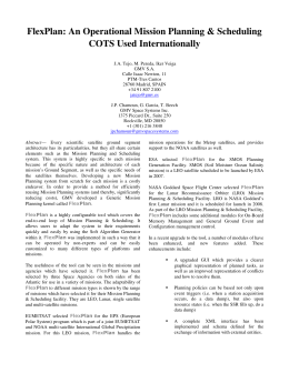
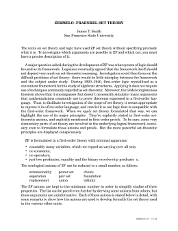
Fig. 4.1 Cockpit display of traffic with conflict detection symbology (red)
The part transferring most of the ASAS information to the human is the display. The
considerations, that led to the current display design, include the following:
-27NLR-TP-2002-170
-
No extra display with dedicated traffic & conflict function (retrofit, integrate info)
-
Absolute co-ordinates (latitude, longitude) frame for conflicts to avoid a separate mode on
navigation display
-
Colours should indicate urgency based on time to loss of separation
-
Traffic symbols should present as much information as possible without clutter (led to
directional aircraft symbols instead of track vectors)
-
Symbology should be transparent
The conflict resolution of the modified voltage potential is based on the geometry of the
conflict. The figure that has been used to explain this algorithm also formed the start for the
symbology. The display, showing a conflict, is depicted in the figure above.
The symbology is presented on the map mode of the navigation display. Nominally the crew
would select the ‘centre mode’ as well that places the ownship symbol in the centre of the
display. Based on average cruise speeds and the look-ahead time of five minutes a range setting
of about 100 nautical mile would be recommended.
This example picture shows a high-density traffic situation. For de-cluttering the display there
are several options. Every line of the text label can be switched off. The vertical range setting of
the vertical display also determines the block of air that is viewed on the horizontal display. So
zooming in on the vertical scale will reduce the number of aircraft shown on the horizontal
display. Any aircraft above or below the altitudes on the vertical scale will not be shown unless
it is a conflicting aircraft. In the same way the vertical display can be de-cluttered by reducing
the horizontal scale. By only viewing this selected block of air, an airspace that would look
extremely crowded on a radar screen could still be monitored on the CDTI. During climb or
descent larger vertical scale selections might be required and extra measures should be added to
the current display to avoid clutter in future situations with an extremely high traffic density. A
vertical offset of the aircraft symbol on the vertical display would reduce the clutter on the
horizontal display in this situation.
The conflict symbology shows the protected zone of the intruder at the closest point of
approach. The cylinder is shown as a circle on the horizontal display and a rectangle on the
vertical display. Depending on the horizontal and vertical scale the crew has selected, the height
of the rectangle is in general quite exaggerated: the actual width to height ratio is 30 to 1, when
using the current separation minima. These dimensions are also the reason the vertical solution
is in most cases the preferred manoeuvre. Therefore including the vertical dimension is very
important for a CDTI that is used for conflict resolution.
-28NLR-TP-2002-170
Red conflict symbology means the separation minima will be violated within 3 minutes, amber
means within 5 minutes but more than 3 minutes. Sometimes conflicts would disappear for a
short time and appear again despite the filters. In this case it often refers to aircraft which are
predicted to skim the protected zone. In the display the conflicting aircraft would still be
coloured amber or red for while to indicate which aircraft the conflict concerned.
The predictive ASAS bands mean: do not select a value (i.e. place the blue selection marker for
heading, vertical speed or speed) in these bands or it will trigger a conflict alert. Filters prevent
conflict alerts when passing through the bands to a selected value beyond the PASAS bands.
4.3 Aural alerts
Two aural alerts are used to differentiate the urgency of the conflict. A conflict within 3 minutes
(red conflict) uses a more imminent sounding alert than a 5 minute conflict (amber conflict).
Both sounds are distinctive from other sounds in a civil cockpit. The ‘threat’ sounds of a
military cockpit have been used. For amber the ‘painted’ sound is used and for red the ‘painted
and locked’ sound of an F-18 Hornet cockpit.
5
Human-in-the-loop experiments
5.1 Phase I flight simulator trials
Two simulator studies have been performed within the study. The first experiment used 18
subject airline pilots. The experiment matrix consisted of three traffic densities x three autopilot
resolution modes x nominal/non-nominal. Every subject crew flew the concept in two days
including half a day of training. The second experiment used the predictive ASAS system and
investigated mixed equipage procedures. ATC controllers were also subjects in this study
controlling the non ASAS equipped aircraft.
-29NLR-TP-2002-170
RFS
AIRSIM
TEM
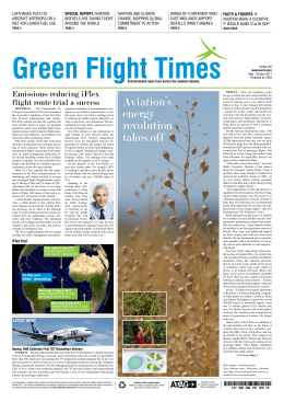
Fig. 5.1 Simulation configuration for human-in-the-loop trials
The first flight simulator experiments were set-up to introduce human factors problems in the
cockpit by using a very high traffic density and an extremely high conflict rate. The idea behind
this set-up was to demonstrate human factors issues under this excessive workload situation.
This result was not obtained. The first reaction of the first crew that came out of the simulator
cockpit after flying in triple Western European traffic density and nine times the amount of
conflicts was: ‘It’s a fine system but what if it gets busy?’. And this was while using the Mark 1
ASAS system without the predictive ASAS, which greatly enhances the situational awareness.
Because of the display design they were only monitoring a part of the airspace and their only
focus was their own aircraft, in contrast to an air traffic controller who has to monitor the
complete sector and control all aircraft. So apparently what is extremely busy for an air traffic
controller is not perceived as such by a cockpit crew flying in a Free Flight airspace. Apart from
objective data logging also a lot of questionnaires have been used during the experiments. Some
of the most striking results have been found in the questionnaires on workload, subjective safety
and acceptability. They are shown in the figures below.
-30NLR-TP-2002-170
Fig. 5.2 Subjective workload scale used in the study
Workload - Traffic Density
( p < 0.0086 )
50
RSME rating
40
30
20
10
0
Single
Double
Triple
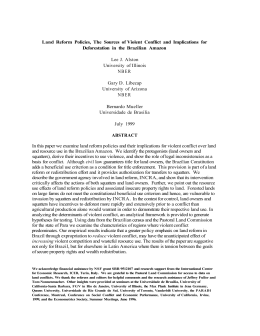
Fig. 5.3 Workload rating as function of traffic density.
Compare with ATC reference value 27 for single density !
-31NLR-TP-2002-170
The workload has been rated on a Rating Scale of Mental Effort (RSME) of 0 –150. The figure
above shows the effect of resolution execution on workload, the largest effect observed. The
rating of 27 was also observed in earlier experiments during the cruise under normal ATC
operations. The sessions on the last half-day of the two day experiment also averaged this value
independent of resolution execution method. This means no increase in workload was indicated
even while the task of separation was added to the cockpit tasks. When confronted with this
result the subject pilots were not surprised. They commented that the traffic display relieves
them from maintaining a mental picture of the traffic situation based on the radio messages,
which is what they do today. In some areas of the world without radar coverage this is essential
in ensuring a safe operation. So by adding the ASAS system and the traffic display with the
separation task this does appear to have both an increasing and decreasing effect on workload
which causes an average observed value that is the same for airborne separation and ground
controlled separation.
The subjective acceptability was rated using a scale of 1 to 5:
1. = Completely Unacceptable
2. = Undesirable
3. = Acceptable
4. = Favourable
5. = Perfect in every way
The acceptability ratings for the flights show an effect of traffic density (see figure below).
Figure 5.4 Traffic density effect on acceptability rating
-32NLR-TP-2002-170
The total variation in the acceptability, though statistically significant, does hardly change due
to the increasing density. Even in triple density (with a nine times as high conflict rate) the
concept was still rated on average above 3 (between favourable and acceptable).
The subjective safety rating also uses a scale of 1-5 to compare the impression of safety to
today’s controlled flights:
1. = ATC much safer
2. = ATC safer
3. = same as ATC
4. = FF safer than ATC
5. = FF much safer than ATC
The largest effect on subjective safety seen was traffic density.
Fig. 5.5 Traffic density effect on subjective relative safety
The subjective safety was rated the same as normal ATC for current traffic densities. For the
same traffic density the safety was rated a bit higher, while for triple densities the average rating
was just (not statistically significant) below today’s ATC with today’s density.
5.2 Phase II flight simulator trials
The two main research questions for the phase II trials were:
- What would the effect of the conflict prevention system PASAS be?
- Which mixed equipage concept that has implicit benefits for equipage seems feasible from a
human factors perspective?
-33NLR-TP-2002-170
Now also an air traffic controller's station was part of the simulation configuration with a
number of controllers as subjects.
A striking result of the second set of simulator trials was that the crews now had a much better
situational awareness as a result of the PASAS bands. The PASAS system also often allowed
them to prevent not just conflicts but also conflict alerts.
The following three mixed equipage concepts were tested. For all it was assumed that the
unequipped aircraft will be visible to the equipped aircraft by means of a TIS-B ground station.
5.2.1 Concept F: Flight Level Split
In this condition, the airspace above a certain altitude (the “Lower Free Flight level”) is reserved
for equipped aircraft only. A transition layer just above the Lower Free Flight level is used as a
buffer zone for aircraft transitioning to and from Free Flight, see figure 5.6.
Fig. 5.6 Flight level split ATM procedure
This buffer zone is used to avoid predicted conflicts and possible intrusions of protected zones
between free flying and controlled aircraft, which would occur if only a single Free Flight Level
were to be used. Flying high has a clear economic advantage for cruising aircraft. Another
advantage of this method is that it allows a gradual transition to free flight by lowering the
altitude limit, similar to the National Route Program in the US (FAA, 1992 & FAA, 1994). This
gradual transition could increase the acceptability of the introduction of Free Flight.
-34NLR-TP-2002-170
5.2.2
Concept A: Protected Airways ATM concept
In this concept, the airspace structure remains largely intact. Airways are still present for
controlled, unequipped aircraft. The ASAS equipped aircraft, however, have the right to leave
the airways for direct shortcuts to their destinations, whereas the controlled aircraft have to stay
within the airways.Free Flying aircraft have the right to cross an airway but only if they ensure
conflict-free passage (as unequipped aircraft are visible on the display).
Fig. 5.7 Protected airways ATM procedure
5.2.3
Concept M: Fully Mixed
Fig. 5.8 Fully mixed ATM concept: longer lookahead times for controlled flights
-35NLR-TP-2002-170
In this case, all aircraft are able to fly direct routing. The controlled aircraft are monitored by the
ground (ATC) using the same conflict detection module as is used in the airborne ASAS. ATC
performs the conflict resolution task for the unequipped aircraft. By using a substantially longer
look-ahead time for the conflict probing for the unequipped aircraft, these aircraft will always
avoid ASAS equipped aircraft without a need for the equipped aircraft to manoeuvre. In the
experiment the ground tools used a lookahead time of 8 minutes while in the air 5 minutes
lookahead time was used. If all works as intended, the equipped aircraft will never detect a
conflict with an unequipped aircraft because this will be resolved before it will be in the lookahead time of the ASAS equipped aircraft. The equipped aircraft have effectively right-of-way
and will not even get a conflict alert.
This is the most beneficial concept for the unequipped aircraft and therefore provides the lowest
benefits for equipage. The drawback of this approach is the high controller workload in busy
areas with a low equipage ratio because of the direct routing.
From the pilot workload results, the fully mixed was the most desirable. See figure 5.9.
Pilot subjective workload
ATM procedure main effect (p<0.097)
Medium traffic
density only
1
0.8
RSME (Z-score)
0.6
0.4
0.2
0
-0.2
-0.4
-0.6
-0.8
-1
Protected airways
Full mix
Flight level
ATM procedure
Fig. 5.9 Pilot workload results for different concepts reach only
90% significance but show fully mixed concept has lowest workload
For the Air Traffic Controllers the reverse trend was found: the full mix received the highest
workload ratings. It seems the problem is moved back and forth depending on the concept
choice. There was no clear indication for one best concept.
-36NLR-TP-2002-170
6
Distributed systems vs. centrally controlled systems
6.1 Introduction
As mentioned in the introduction, Free Flight is more than merely the introduction of a new
procedure or a new tool. It is a fundamental change in the structure of the ATM system. The fact
that the control becomes distributed causes a lot of distrust in the system. This may have more
to do with the way we think than with the distributed aspect itself. Because the system becomes
a collection of active agents it is in fact comparable to parallel processing: many conflicts can be
handled at the same time. All these actions are caused by the interaction via the geometry. The
parallel, geometrical and interactive aspects make it hard to mentally simulate or imagine the
course of events in a distributed system. It is therefore less easily trusted than a centrally
controlled system, which is more predictable. There is a fear of chaos as a result of the
distributed effect. One could say: rather a safe chaos, than a dangerous order. Still examples like
deadlocks and trapping multi-aircraft conflicts seem to require a central controlling element.
These situations however could only cause problems in an airspace so full of aircraft that a
centrally controlled system would never have been able to handle it in the first place, because of
the overload of the central node. The real relevant effects of changing a system from centrally
organised to a distributed are the robustness of the system and the immense increase in capacity.
The apparent chaos is also not real chaos: the same resolution algorithm governs the whole
system. This means there is some order, which is able to cause large scale orderly patterns,
comparable with waves consisting of interactions of molecules.
6.2 Robustness
The robustness of the Free Flight concept became evident when setting up the flight simulator
experiment. One set of runs was used to explore the human factors of non-nominal cases like
failures, delays, counteracting crews, etc. Just failing the conflict detection module did not yield
a very interesting event: because the other aircraft’s crew initially assumes the conflicting
aircraft does not manoeuvre the conflict was still solved, only this time completely by the other
aircraft. The crew would not notice the situation and no dangerous situation requiring them to
notice would occur. To cause problems the other aircraft’s conflict detection would also have to
be failed. So two aircraft with a failing system are required for a real danger due to conflict
detection failure. And of all combinations of all the aircraft in the free flight sector, these two
should be the ones, which will have a conflict. Compared to the centrally organised system: this
would just require a failure of the radar screen or update to cause a globally dangerous situation
for any combination of conflicting aircraft.
-37NLR-TP-2002-170
6.3 Capacity
An air traffic controller is managing his/her workload most of the time by preventing conflicts
long before they would happen. He is indeed separating traffic instead of solving conflicts. If he
would not do this, he might be trapped in a situation requiring more than one action at a time to
prevent conflicts. Because of the limits of the human controller and the radiotelephony, parallel
processing is not possible. This is also a limiting factor for the capacity of the airspace. One
controller has a limit to the number of aircraft in his sector. With increasing air traffic this
means the sector size should be decreased, maybe even depending on the local traffic density.
This causes two problems (1) we could end up with ‘stamp-sized’ sectors (2) workload might
actually increase due to greater inter-sector co-ordination demands.
The difference with a distributed system is clear: with every aircraft entering the free flight
sector, two potential controllers (in case of a standard two man crew) are added to the situation
as well. A lot of conflicts can be solved at the same time without any stress by the cockpit crew
because everyone is taking care of only his own conflicts. In the flight simulator, traffic
densities have been simulated over ten times the current day traffic density (though not yet in a
real experiment with 18 subject pilots). In these extremely high density scenarios the ASAS
system (without using intent but with PASAS) and in a worst case mixed equippage scenario
(airway-like route structures etc.) it was still manageable without an unacceptably high
workload. In the same set-up with the same sector size during experiments, air traffic controllers
gave up when the traffic density was higher than doubled compared to today.
6.4 Bottleneck conflicts
The notion that Free Flight is not feasible because it is dangerous to distribute control is often
illustrated by examples of bottleneck scenarios. As an analogy for these situations, some
conflict geometries have been constructed. These situations will in general give the impression
that some form of central co-ordination is required to solve them. However, if they do solve
very efficiently (with minor deviations from the original track) without central control then it is
an illustration of how counter-intuitive the effect of distributed control can be. It is the
experience of the author that the examples described in this chapter are very persuasive
concerning the feasibility of separation assurance without central control.
Two types of conflicts that were regarded as very critical are described in this chapter:
•
“super-conflicts” - circular conflicts, which require a high number of parallel actions to
solve efficiently
•
“the wall” - one wall of aircraft already separated at minimum distance where one aircraft
needs to go through
-38NLR-TP-2002-170
In both examples, the vertical solution has been disabled to make it more constraint.
Fig. 6.1 Superconflict with 8 aircraft with the vertical resolution disabled (Note the circles have
a radius of 2.5 nm so touching circles mean the separation is still 5 nm)
-39NLR-TP-2002-170
Even with a superconflict of 16 aircraft, the superconflicts are solved without intrusions.
In the wall scenario the centre aircraft opposing the wall creates a wave through the wall which
causes the wall to ripple and thus make space for the aircraft to go through.
Fig. 6.2 One aircraft heading at a 'wall' of traffic at minimum separation distance. The initial
conflict causes a wave in the wall creating a hole for the opposing aircraft
-40NLR-TP-2002-170
7
Conclusion
7.1 Feasibility
Based on the results and discussion in the previous section, the most important result of this
study is that the feasibility of Free Flight, the combination of direct routing and airborne
separation assurance, in upper airspace could not be refuted. Even in high traffic densities Free
Flight proved capable of maintaining the separation minima in a direct routing concept better
than today’s ATM system. This result is supported by the results of flight simulator experiments
using airline pilots in simulated en-route, high traffic density airspace, by off-line traffic
simulations and by analysis.
7.2 Operational Concept
This study proposes an operational concept for Free Flight in upper airspace for further research
and implementation efforts. The concept requires a state-based conflict detection, resolution and
prevention system and implicit co-ordination using only two straightforward, common rules-ofthe-sky:
1. As soon as a state-based conflict is predicted within the specified lookahead time, an aircraft
should not manoeuvre so as to decrease the distance at the predicted closest point of
approach, but resolve the conflict if possible.
2. It is not allowed to initiate a manoeuvre that will result in a state that triggers a state-based
conflict alert within the specified lookahead time.
Exceptions to these rules are situations where a higher priority threat, such as terrain or a more
urgent conflict, can not be solved without violating these rules. This basically leaves solving
this lower priority threat to the other aircraft involved. In the rules the word state refers to only
the three-dimensional position and three-dimensional velocity vector.
The lookahead time is dependent on the airspace, flight phase and separation minima. For enroute traffic and the current separation minima, five minutes proved to be an acceptable value in
this study.
7.3 Capacity Benefits
In a direct routing environment the airspace is used more efficiently than in a concept where
aircraft have to follow one-dimensional airways. Free Flight proved to be able to handle higher
traffic densities than today’s centralised ATM system. Under simulated traffic loads that exceed
the capacity of today’s ATM system, very low pilot workload has been found and pilot
acceptability was found to be high. By system analysis indications have been found that a
-41NLR-TP-2002-170
distributed ATM system, like Free Flight, has a structural capacity advantage over any centrally
organised ATM concept. Together with the observation that the majority of today’s European
ATC-related delays are caused by en-route congestion (Eurocontrol PRC, 1999), this means
Free Flight could provide the solution for the current delay problem in Europe.
7.4 Economic Benefits
Free Flight is a potential enabler of direct routing. Direct routing has been the Holy Grail in
ATM research for a long time. The economic benefits of direct routing will be substantial
compared to past efforts to increase the efficiency of the ATM system. Reducing delays is
another economic benefit. The costs to upgrade the avionics will (and should) be much less than
the potential benefits. The main reason why cockpit technology is expensive is because of the
certification costs. By using a simple system as proposed in this study, these costs should allow
to build a long-term business case for Free Flight. This long-term vision is crucial for the
survival of the air transport sector and future work should focus on this.
7.5 Safety Benefits
The actual safety of Free Flight is hard to determine because of the number of open issues.
Especially the specifications of the technology that will be available are still largely unknown.
However, the fundamental change from a centrally organised system to a distributed system is
potentially beneficial for the safety. This may be understood by comparing it with a simple
example. How would collisions be better avoided? By having a number of blind-folded people
walking in an area communicating with one monitoring controller or by taking the blindfolds
away and allowing the people to walk and watch out by themselves? Another way to look at this
fundamental change is to compare the situational awareness of one controller with the collective
situational awareness of all pilots in a Free Flight airspace.
The de-centralisation and the inherent redundancy of the distributed system with implicit coordination contribute to the potential increase in safety.
-42NLR-TP-2002-170
References and Bibliography
Allen, D. L.; Haraldsdottir, A.; Lawler, R. W.; Pirotte, K.; Schwab, R.W. (1997). “The
Economic Evaluation of CNS/ATM Transition”, ATM 97 Conference paper, CNS/ATM
projects, Boeing Commercial Airplane Group
Berghuis van Woortman, H.J. & Aardoom, W. (1991).“Cursus luchtverkeersleiding (lr94)”, 5th
Issue, November 1991, lr94, Technical University Delft, Faculty of Aerospace Engineering
Billings, C.E. (1997). “Aviation automation: The search for a human-centered approach.”
Mahwah, New Jersey: Lawrence Erlbaum Associates.
Boeing Commercial Aircraft Group (1994). “Statistical summary of commercial jet aircraft
accidents, worldwide operations 1959-1994.” Seattle, WA: The Boeing Commercial Airplane
Group.
Cashion, P. & Lozito, S. (2000). “How Short- and Long-term Intent Information Affects Pilot
Performance in a Free Flight Environment”, San Jose State University, NASA Ames Research
Center, HCI-Aero conference 2000 paper
Combs, A. & Rippy, L. (2000). “Distributed Air Ground- Traffic Management Intent
Preference Experiment”; Airborne Systems, Crew Systems and Operations Branch; NASA
Langley
Donovan, J. & Joseph, K.M. et al.(1998). “Human Factors Issues In Free Flight”, SAE G-10
Aerospace Resource Document (ARD) No. 50079
Duong, V. & Floc’hic, L. (1996). “FREER-1 Requirement Document version 2.0 ”, Eurocontrol
Experimental Centre EEC Bretigny, France
Eby, M.S. (1994). “A Self-Organizational Approach for Resolving Air Traffic Conflicts”, The
Lincoln Laboratory Journal, MIT, Vol. 7, Nr. 2, 1994, page 239 - 254
Eurocontrol Experimental Centre (1997). “User Manual for the Base of Aircraft Data (BADA)”
Revision 2.5, EEC Note 1/97, Eurocontrol, 1997
Eurocontrol (1998). “Eurocontrol Air Traffic Management Strategy 2000+ Operational Concept
Document”, EATMS OCD (edition 1.1, 14.8.98) EATCHIP, 1998
-43NLR-TP-2002-170
Eurocontrol PRC (1999). “Annual Report of Eurocontrol Performance Review Committee
1999”, Eurocontrol, 1999
FAA (1992). “National Route Program”, Advisory Circular (AC) No. 90-91, ATM-100, April
24, 1992
FAA (1994). “National Route Program (NRP)”, FAA Order N7110.128 Free Flight, ATM-100,
effective January 9, 1995
FAA (1999). “Interim Guidance 91-RVSM”, change 1 AFS-400, June 30th 1999, FAA AFS400
FAA (2000). “Air Traffic Control”, August 2000, FAA TP 07110.65M
FAA AIM (2000). “Aeronautical Information Manual” (AIM), FAA, Edition August 2000,
Chapter 4
Goldberg, D.E. (1989). "Genetic Algorithms in Search, Optimization, and Machine Learning",
Addison-Wesley, 1989
Hilburn, B.; Pekela, W. (1999). “Free Flight and the Air Traffic Controller: Results of AirGround Integration Experiments”, SAE World Aviation Congress 1999 paper 1999-01-5563
Heitkoetter, Joerg and Beasley, David, eds. (1994). "The Hitch- Hiker's Guide to Evolutionary
Computation: A list of Frequently Asked Questions (FAQ)", USENET : comp.ai.genetic.
Available via anonymous FTP from ftp://rtfm.mit.edu:/pub/usenet/news.answers/ai-faq/genetic/
About 90 pages.
Hoekstra, J.M. (2002), "Designing for Safety: the Free Flight Air Traffic Management" ISBN
90-806343-2-8, National Aerospace Laboratory NLR, Netherlands, November 2001
Horn, R.E. (1998). “Visual Language”, Robert E Horn, MacroVU Press, Washington, 1998
ICAO Annex 11. “ICAO Annex 11” International Standards and Recommended Practices - Air
Traffic Services, ICAO
ICAO Circular 249-AN/149 “Guidelines for Human Centred Automation in Aviation”
-44NLR-TP-2002-170
ICAO (1992). “Application of Separation Minima (North Atlantic Region)”, ICAO, publ. by
Transport Canada, 3rd edition, Dec 1992
Kuchar J.K. & Yang, L.C. (1997). “Survey of Conflict Detection & Resolution Modelling
Methods”, AIAA GN&C conference 1997
Langton, C.G. (1997). “Artificial Life: An Overview (Complex Adaptive Systems)”,
Christopher G. Langton, Bradford Books, March 1997
Lozito, S. & McGann, A. et al (1997). “Free Flight and Self-Separation from the Flight Deck
Perspective”; NASA Ames Research Center, San Jose State University, paper ATM ‘97
Conference
Magill, S.A.N. (1997). “Trajectory Predictability and Frequency of Conflict Avoiding Action”,
Defence Evaluation and Research Agency (DERA), paper CEAS Free Flight Conference 1997
Merwin, D., O'Brien J. V., & Wickens, C. D. (1997). “Perspective and coplanar representation
of air traffic: Implications for conflict and weather avoidance.” Proceedings of the 9th
International Symposium on Aviation Psychology. Columbus, OH: Dept. of Aerospace
Engineering, Applied Mechanics, and Aviation, Ohio State University
Nyhoff, L. & Leestma, S. (1996). “Fortran 77 for Engineers & Scientists”, Prentice Hall, 1996,
ISBN 0-13-363003-X
Parasuraman, R., Molloy, R., & Singh, I. (1993). “Performance consequences of automation
induced "complacency"”, International Journal of Aviation Psychology, 3(1), 1-23.
Ross Russell, J. (1995). “The Separation Game”, IFR magazine, Belvoir Publications Aviation
Group, archived at Avweb: http://www.avweb.com/articles/separat.html
RTCA TF 3 (1995). “Final report of RTCA Task Force 3: Free flight implementation” RTCA
Task Force 3, 1995, RTCA Inc., Washington DC, chapter 3
RTCA (2000). “Operational Concept for Airborne Conflict Management”, RTCA SC-186 ACM
subgroup, 2000, RTCA Inc., Washington DC
-45NLR-TP-2002-170
Valenti Clari, M.S.V. (1998). “Cost-Benefit Analysis of Conflict Resolution Manoeuvres in
Free Flight” M. Sc. Thesis Delft University of Technology, Faculty of Aerospace Engineering,
Flight Mechanics group, August 1998
Van Gent, R.N.H.W., Bohnen, H.G.M., Jorna, P.G.A.M. (1994). “Flight Simulator Evaluation
of Base Line Crew Performance with Three Data Link Interfaces”, NLR, 1994
Vesely, W.E., Goldberg, F.F., Roberts, N.H., Haasl,D.F. (1981). “Fault Tree Handbook”, U.S.
Nuclear Regulatory Commission, 1981
Wickens, C.D. (1992). “Engineering psychology and human performance” (2nd ed.). New
York: Harper Collins
Wickens, C.D. et al. (1997). “Flight to the Future: Human Factors in Air Traffic Control” Christopher D. Wickens, Anne S. Mavor, and James P. McGee, Editors; Panel on Human
Factors in Air Traffic Control Automation, National Research Council, National Academy
Press,Washington, D.C. 1997
Wolfram S. (1984). “Cellular Automata as Models of Complexity”, S. Wolfram, Nature, 311,
(October 1984) 419--424
Zijlstra, F.R.H & Doorn, L. van (1985). “The construction of a scale to measure subjective
effort.” Technical Report, Delft University of Technology, Department of Philosophy and
Social Sciences, Netherlands
Baixar