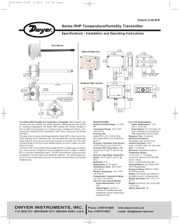
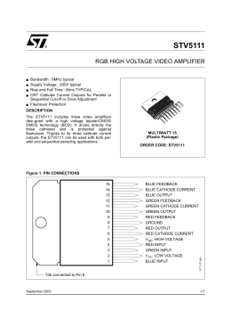
Maxim > Design Support > Technical Documents > Application Notes > Sensors > APP 3364
Keywords: smart sensor, signal conditioner, compensator, digital signal conditioner, high resolution, PRT
sensor, Thick Film sensor, Thin Film sensor, strain gauge, RTD
APPLICATION NOTE 3364
Creating a Ratiometric Current Excitation in
Sensors Using the MAX1464 Signal Conditioner
By: Youssof Fathi
Dec 10, 2004
Abstract: The MAX1464 can be easily configured to generate constant current excitation for sensors that
is ratiometric to the power supply voltage for resistive transducer applications. Applications utilizing
sensing elements with high temperature coefficients, TCR, such as piezo resistive bridges, RTDs, etc.
are typically implemented with constant current excitation. This application note suggests a simple
resistive network that can be implemented to provide a ratiometric current source for sensor excitation.
Applications using sensing elements with high temperature coefficients, TCR, such as piezo resistive
bridges, RTDs, etc. are typically implemented with constant current excitation. The MAX1464 can be
easily configured to generate constant current, ratiometric to the supply voltage, for resistive transducer
applications. This application note suggests a simple resistive network to provide the ratiometric current
source. To reduce external components, the uncommitted op-amps internal to the MAX1464 can be
used.
The MAX1464 is a highly integrated programmable sensor signal conditioner with two input/output
channels and 16-bit resolution and provides for signal amplification, calibration, linearization, and
temperature compensation. The MAX1464 supports a choice of analog or digital outputs including 4–
20mA, ratiometric 0.5V to 4.5V, and PWM.
Many of today's sensor applications use sensing elements, such has piezo-resistive sensors, that have
very high temperature coefficient of resistance (TCR), and sensitivity (TCS). These two coefficients are
typically of comparable values, but opposite signs. To minimize the overall temperature dependency and
improve performance of the sensing elements, the sensing element is normally driven with constant
current. The MAX1464 can be configured to generate a constant current for these applications. Figure 1
shows a simple resistive circuit that generates the constant current IB for excitation of the sensing
element RB. The equations that apply to the circuit in Figure 1 are given below. Figure 2 shows the
resulting ratiometric current for VDD ranging from 4.5V to 5.5V.
Page 1 of 4
Figure 1. Constant current source circuit for the MAX1464 applications.
Figure 2. Excitation current is ratiometric to VDD.
Values of resistors R1 and R2 in Figure 1 must be selected such that the current (IR1) drawn from the
VDD line will not overload the power supply or does not compromise the sourcing capability of the VDD
line to supply the MAX1464 signal conditioner.
The current IR3, through the resistor R3, is equal to V3/R3 and the only source for this current is the
op_amp LG. Hence, IB = IR3. Since the voltage V2 is proportional to the ration of R1 and R2 resistors,
as long as R1 and R2 have identical TCRs, the voltage V2 (and hence V3, V2=V3) will be independent
Page 2 of 4
of the environment temperature. However, the current IR3 will change with temperature due to TCR of
R3. Since IB = IR3, the voltage VB will also be affected by TCR of R3. To minimize the effect of R3 on
temperature performance of the sensor, a resistor with smallest TCR possible must be used. Additionally,
VB will also change with temperature due to TCR of the transducer's input impedance. A typical piezoresistive transducer has TCR of about 3000 PPM that accounts for the bulk of the change in VB over
temperature. In a typical application of the MAX1464, this will not be an issue since all temperature
errors will be lumped together and will be corrected by the compensation algorithm.
Equations: IB = IR3
VB = IB × RB
(1)
(2)
Where RB is the transducer's input impedance
IR3 = V3/R3
(3)
V3 = V2 = VDD × R2/(R2 + R1)
(4)
IR1 = VDD/(R1 + R2)
(5)
When selecting the application parameters, select the excitation current, IB, such that (VB+V3)<VDD
over all temperature conditions. The capacitor C1, in Figure 1, is added to filter out noise on the
sensor's excitation signal. In applications where the signal noise is within the acceptable limits, C1 is not
necessary.
Example:
The following component values will generate 0.455mA current for sensor excitation when VDD=5V and
remains ratiometric to the VDD as the VDD ranges from 4.5V to 5.5V:
R1 = 10.0kΩ; R2 = 1.0kΩ; R3 = 1.0kΩ
Applying these values to the equations gives V2 = 0.455V and V3 = 0.455V. Equations 3 and 1 show the
bridge current to be IB = 0.455mA. Equation 5 shows the VDD supply is not excessively loaded with IR1
= 0.455mA. Also, for a transducer with bridge impedance of 5kΩ, a bridge voltage of VB = 2.27V will be
generated.
In sensor applications where the transducer and the signal conditioner are at different temperatures, the
transducer bridge voltage VB can be connected to one of the MAX1464 input channels and be utilized as
the sensor temperature indicator provided that the TCR of the resistor R3 is known or negligible.
In the suggested circuit below, LG represents the internal 'Large' op-amp of either one of the MAX1464
output channels. In real applications, the unused 'Large' or 'Small' internal op-amps of either output
channels or an external op-amp can be used.
References:
MAX1464 Datasheet
Related Parts
MAX1464
Low-Power, Low-Noise Multichannel Sensor Signal
Free Samples Page 3 of 4
Processor
More Information
For Technical Support: http://www.maximintegrated.com/support
For Samples: http://www.maximintegrated.com/samples
Other Questions and Comments: http://www.maximintegrated.com/contact
Application Note 3364: http://www.maximintegrated.com/an3364
APPLICATION NOTE 3364, AN3364, AN 3364, APP3364, Appnote3364, Appnote 3364
Copyright © by Maxim Integrated Products
Additional Legal Notices: http://www.maximintegrated.com/legal
Page 4 of 4
Baixar