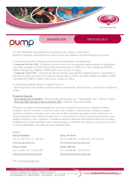
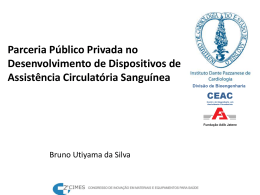
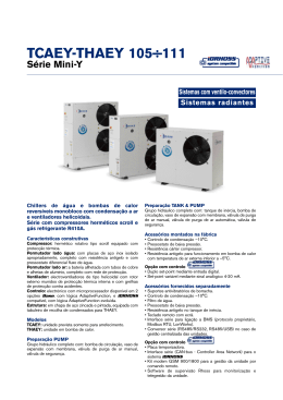
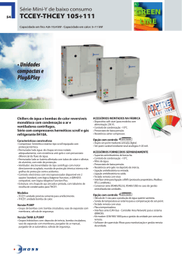
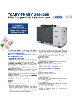
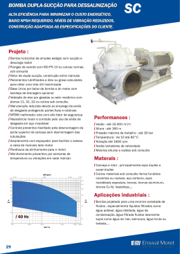
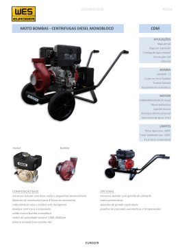
PORTUGUÊS
CMH
- Deve procurar-se que esteja a
salvo de possíveis inundações e em
- Antes de proceder à instalação, leia
lugar ventilado e seco.
1. RECOMENDAÇÕES
atentamente o conteúdo do presente
manual. Ele pretende fornecer toda a
informação necessária para a
instalação, uso e manutenção das
bombas CMH (Centrífuga
Multicelular Hori-zontal).
- É importante que o utilizador leia
este manual antes de usar a bomba.
- Os danos provocados na
electrobomba, pelo não cumpri-mento
das indicações descritas a seguir,
obrigam à perda da garantia.
- No momento da recepção
da electrobomba, verifique
se esta não sofreu danos
durante o transporte.
- Neste caso, alerte imediatamente
o nosso agente.
2. CONDIÇÕES DE FUNCIONAMENTO:
4. MONTAGEM DOS TUBOS:
- A tubagem de aspiração (Fig.1) deve
ter um diâmetro igual ou superior ao
orifício de entrada da bomba,
conservando uma incli-nação
ascendente de pelo menos 2%, para
facilitar a purga.
- É imprescindível a colocação de uma
válvula de pé, com filtro, submersa pelo
menos 30 cm abaixo do nível dinâmico
do poço, para evitar remoinhos e
consequentes entradas de ar.
- Procure que a tubagem de
compressão (Fig. 1) tenha um diâmetro igual ou superior ao orifício de
saída da bomba.
- Nem a tubagem de aspiração nem de
compressão devem ficar sus-pensos da
bomba.
TUBAGEM DE
COMPRESSÃO
- São bombas centrífugas concebidas
para trabalharem com água limpa,
com temperatura máxima de 40o C.
3. INSTALAÇÃO:
- A bomba deve fixar-se a uma base
sólida mediante parafusos,
TUBAGEM DE
Fig. 1
ASPIRAÇÃO
aproveitando os orifícios existentes
nas patas do motor, com o objectivo de 5. LIGAÇÃO ELÉCTRICA:
evitar ruídos e vibrações indese-jáveis. - Os motores monofásicos têm
- Deve colocar-se o mais
próximo possível do nível da água
a fim de obter al-tura de aspiração
mínima e reduzir as perdas de
carga.
protecção térmica incorporada.
- A instalação eléctrica deverá dispor de
um sistema de separação múltipla com
abertura de contactos de pelo menos
3mm.
Instruções para uso e dados técnicos
Instructions for use and technical data
Avenida Santiago, N.º 43
Zona Industrial de Rio Meão - 4520 Rio Meão PORTUGAL
Telef. 351.56.783742/780910 - Fax 351.56.783880
Web: www.oliju.com
ELECTROBOMBAS Email: [email protected]
PORTUGUÊS
PORTUGUÊS
- A protecção do sistema basearse-à 6. CONTROLES PRÉVIOS AO
num interruptor diferencial ( I FN =
ARRANQUE INICIAL:
30 ma ) . O cabo de alimentação
deve cor-responder à norma CEE - Comprove que a tensão e frequência de rede correspondem às
(2) ou ao tipo H07 RNF.
indicadas na placa de caracterís-ticas.
- Assegure-se de que o veio do
M
1~
motor roda livremente.
- Encha completamente de água o
corpo da bomba e a tubagem de
Fig. 2
aspiração, através do bujão de
ferragem (Fig. 4), assegurando-se de
ALIMENTAÇÃO
N L
MONOFÁSICA
que não existe nenhuma junta ou
união com fugas.
- No caso das bombas trifásicas a
protecção deve ser prevista pelo
utilizador segundo as normas de
instalação vigentes.
- Os esquemas da Fig.3 facilitam a
correcta ligação eléctrica.
ALIMENTAÇÃO TRIFÁSICA
400V
- Verifique se o sentido de rotação do
motor coincide com o indicado na
tampa do ventilador. Na versão
monofásica o sentido já é prede-finido.
Nos motores trifásicos, se o sentido de
rotação estiver errado, inverta duas
fases no quadro de protecção.
230V
Fig. 3
6. CONTROLES PRÉVIOS AO
ARRANQUE INICIAL:
- Comprove que a tensão e frequência de rede correspondem às
indicadas na placa de características.
- As nossas bombas não necessitam
de nenhuma manutenção específica
ou programada.
Recomenda-se, no entanto, que se esvazie
o corpo da bomba durante os períodos de
baixas temperaturas ou em caso de
inactividade prolongada, através do bujão
de purga (Fig. 5). Se a inactividade
persistir durante muito tempo, deve
limpar-se a bomba e guardá-la em lugar
seco e ventilado.
8. AVARIAS E CAUSAS
- Abra todas as válvulas de seccionamento que existam nos
circuitos de aspiração e com-pressão.
- Verifique a corrente absorvida e
ajuste o relê térmico ( apenas na
versão trifásica).
- Se o motor não funcionar ou não
extrair água, procure descobrir a
anomalia através da relação das
avarias mais habituais e as suas
possíveis resoluções, que facultamos no quadro em baixo.
Fig. 4
Fig. 5
BUJÃO DE PURGA
Antes de tentar diagnosticar qualquer avaria, verifique se a alimentação eléctrica
foi desligada.
AVARIA
CAUSA POSSÍVEL
O bomba não arranca.
-
A bomba trabalha mas não sai
água.
- A bomba não está ferrada.
- Tubos de aspiração ou descarga bloqueados devido a
impurezas.
- Excesso de altura de aspiração.
- Fuga no tubo de aspiração.
- Válvula de pesca/retenção bloqueada.
A bomba funciona a
capacidade reduzida.
- Sentido de rotação errado (trifásica).
- Excesso de altura de elevação.
- Tubos de aspiração ou descarga bloqueados ou
defeituosos.
- Bomba bloqueada devido a impurezas.
- Válvula de pesca ou retenção parcialmente bloqueada.
A bomba para durante o
funcionamento.
- O interruptor térmico do motor ou da protecção exterior
do motor desliga.
- Circuíto de controlo está desligado.
A BOMBA NUNCA DEVE
FUNCIONAR EM SECO.
7. ARRANQUE
BUJÃO DE FERRAGEM
8. MANUTENÇÃO
Falha na corrente de energia.
Circuíto de controlo está desligado ou defei-tuoso.
Motor defeituoso.
Bomba bloqueada devido a impurezas.
Se o problema persistir contacte o serviço de assistência técnica mais próximo.
ENGLISH
ENGLISH
1. GENERAL WARNINGS
- Read this manual carefully before
installing this pump. It contains every
necessary information for installation,
correct use and maintenance of MH
pumps.
- It's very important that the user reads
this manual before using the pump. Any
damage caused by failure to observe the
directions contained in this manual will
not be covered by warranty.
- A foot valve with filter should be
installed and submerged to at least 30
cm below the well dynamic level to
prevent air from entering the pump.
- Be sure that discharge pipe (Pic. 1)
should never rest on top of the pump.
- Follow directions on Pic. 3. for a
correct electrical connection.
THREE PHASE SUPPLY
400V
DELIVERY
8. MAINTENANCE
230V
- By the time you receive this
pump check if it wasn´t damaged
during transportation.
Pic. 3
- In this case, please contact our
agent as soon as possible.
2. OPERATING CONDITIONS:
- The MH are centrifugal multi-stage
pumps and have been designed to
work with clean water at a maximum
temperature of 40º C.
3. INSTALLATION:
- The pump should be fixed to a solid
base by bolts through the holes in the
pump bracket in order to prevent
unwanted noise or vibration.
- You should place pump as
near as possible to water level
so to have the minimum suction
lift and reduce loss of head.
- Make sure that pump is never
submerged and that it rests in a dry and
well aired room.
Pic. 1
SUCTION PIPE
6. CONTROLS PRIOR TO THE
INITIAL STARTING:
- Our pumps do not need any special or
programmed maintenance.
Pump body should , however , be drained
during periods of low temperatures or
long periods of inactivity. To empty
pump, only remove drain plug (Pic. 5). If
the inactivity persisted, pump should be
cleaned and stored in a dry aired room
5. ELECTRICAL CONNECTION:
- The single-phase motors have a built-in
thermal protection.
- The electrical installation must have a
system of multiple separations with
contact opening of at least 3 mm.
- The protection of the system will be
based on a differential swith ( I fn = 30 ma).
- The electric cable must correspond to
the EEC (2) norm or to the type H07 RN-F.
- With three-phase motors, end-user must
install himself the correct protection to the
pump as per the aproppiate installation
regulations.
M
1~
- Check that voltage and frequency
correspond to those indicated on the
technical characteristics label.
- Make sure the motor shaft is turning
freely.
- Fill pump body completely with water,
as well as the suction pipe, through the
priming hole (Pic. 4). Check that there is
no leaking through joints or connections.
- Check to assure that the sense of
rotation of the motor coincides with that
indicated on the fan cover. If you are
checking threephase motor and the sense
of rotation is wrong, invert two phases on
the protection board.
PRIMING HOLE
Pic. 4
THIS PUMP SHOULD NEVER BE
DRY OPERATED.
4. PIPES ASSEMBLY:
- Suction pipe (Pic. 1) must have a
slightly larger diameter than the pump
inlet and must always remain in an
upward inclination of 2% so to help
with correct priming.
- Check absorbed current and adjust
thermal relay conveniently only when
operating with three-phase pumps.
- If motor failed to start or did not pump
water up, refer to our ”Trouble Shooting”
list and identify your problem. Then
follow instruction on what action to take.
7. STARTING
Pic. 2
SINGLE PHASE
SUPPLY
N L
- Open all gate valves installed in the
suction and discharge circuits.
Pic. 5
DRAIN PLUG
ENGLISH
9.FAULT FINDING CHART
Before attempting to diagnose any fault, make sure that the
electricity supply has been switched off.
FAULT
Pump does not start.
Pump runs but gives no
water.
Pump runs at reduced
capacity.
Pump stops during
operation.
CAUSE
- Supply failure.
- Control circuit has cut out or is
defective.
- Motor is defective.
- Pump is blocked by impurities.
- Pump is not filled with liquid.
- Suction or discharge pipe is blocked
by impurities.
- Pump is blocked by impurities.
- Suction lift is too great.
- Leakage in suction pipe.
- Foot or non-return valve is blocked.
- Wrong direction of rotation (threephase).
- Suction lift is too great.
- Suction or discharge pipe is blocked.
- Pump is blocked by impurities.
- Foot or non-return valve is partly
blocked.
- Thermal overload switch in motor or
external motor protection cuts out.
- Control circuit has cut out.
If in spite of carring out the above operations the problem still persists contact the
nearest service centre.
The products , referred to in this statement are in
accordance with Directive 73/23/EEC (the Low
Voltage Directive). Full compliance with
essential requirements of the Directive is
verified for compliance with standard EN
60335-2-41.
As electrobombas CMH,
referidas nesta
declaração, estão em conformidade com a Directiva
73/23/CEE (Directiva de Baixa Tensão). A plena
concordância com os requesitos essenciais da
Directiva é comprovada pela conformidade com a
norma
EN 60335-2-41.
(Gerencia)
Baixar