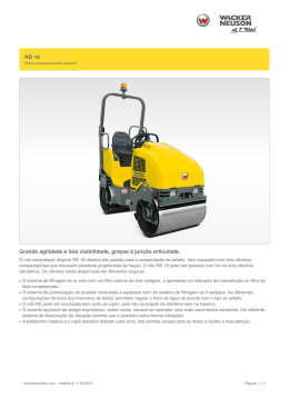
4170162-PT-Rev B
Technical Manual
Manual técnico
Eclipse
InCommand™
63300 –
63313 –
63301 –
63314 –
63302 –
63311 –
63303 –
63312 –
63304 –
63315 –
Eclipse 118, 18” 11 Blade Reel, Gen-Set
Eclipse 118, 18” 11 Blade Reel, Battery Pack
Eclipse 118F, Floating 18” 11 Blade Reel, Gen-Set
Eclipse 118F, Floating 18” 11 Blade Reel, Battery Pack
Eclipse 122, 22” 11 Blade Reel, Gen-Set
Eclipse 122, 22” 11 Blade Reel, Battery Pack
Eclipse 122F, Floating 22” 11 Blade Reel, Gen-Set
Eclipse 122F, Floating 22” 11 Blade Reel, Battery Pack
Eclipse 126, 26” 7 Blade Reel, Gen-Set
Eclipse 126, 26” 7 Blade Reel, Battery Pack
63300 –
63313 –
63301 –
63314 –
63302 –
63311 –
63303 –
63312 –
63304 –
63315 –
Eclipse 118, Rolo de 11 Lâminas de 457 mm, Grupo Gerador
Eclipse 118, Rolo de 11 Lâminas de 457 mm, Bateria Completa
Eclipse 118F, Rolo Oscilante de 11 Lâminas de 457 mm, Grupo Gerador
Eclipse 118F, Rolo Oscilante de 11 Lâminas de 457 mm, Bateria Completa
Eclipse 122, Rolo de 11 Lâminas de 559 mm, Grupo Gerador
Eclipse 122, Rolo de 11 lâminas de 559 mm, Bateria Completa
Eclipse 122F, Rolo Flutuante de 11 Lâminas de 559 mm, Grupo Gerador
Eclipse 122F, Rolo Oscilante de 11 Lâminas de 559 mm, Bateria Completa
Eclipse 126, Rolo de 7 Lâminas de 660 mm, Grupo Gerador
Eclipse 126, Rolo de 7 Lâminas de 660 mm, Bateria Completa
WARNING
If incorrectly used, this machine can cause severe injury. Those who use
and maintain this machine should be trained in its proper use, warned of its
dangers and should read the entire manual before attempting to set up,
operate, adjust or service the machine
ATENÇÃO
Esta máquina pode causar ferimentos graves se for utilizada incorrectamente.
A pessoa responsável pela sua utilização e manutenção deve ser previamente
instruída para a sua utilização correcta, avisada sobre os perigos que ela pode
causar e deve ler todo o manual antes de tentar preparar, conduzir, afinar ou
reparar a máquina.
GB
PT
Portuguese
When Performance Matters.™
FOREWORD
This manual contains safety, operating, adjustment,
maintenance, troubleshooting instructions and parts list
for your new Jacobsen machine. This manual should be
stored with the equipment for reference during operation.
The serial plate is located on the rear crossbar of the
frame. Jacobsen recommends you record these numbers
below for easy reference.
Before you operate your machine, you and each operator
you employ should read the manual carefully in its
entirety. By following the safety, operating and
maintenance instructions, you will prolong the life of your
equipment and maintain its maximum efficiency.
®
A Textron Company
CHARLOTTE, NC
MADE IN U.S.A.
YEAR OF
PRODUCTION:
If additional information is needed, contact your
Jacobsen Dealer.
Suggested Stocking Guide
To Keep your Equipment fully operational and productive, Jacobsen suggests you maintain a stock of the more
commonly used maintenance items. We have included part numbers for additional support materials and training aids.
To order any of the following material:
1. Write your full name and complete address on your
order form.
2. Explain where and how to make shipment:
q UPS
q Regular Mail
q Overnight
q 2nd Day
3. Order by the quantity desired, the part number, and
the description of the part.
4. Send or bring the order to your authorized Jacobsen
Dealer.
Service Parts
Qty. Part No.
Description
Qty. Part No.
4102780 50 Amp Fuse
4169341 25 Amp CIrcuit Breaker
4131618 Ignition Key
Description
2811106 Motor to Pulley Belt
2811070 Pulley to Traction Drum Belt
Service Support Material
Qty. Part No.
Description
Qty.
4170162 Technical Manual
4166960 Operator Training Video
Description
Service Manual
Proposition 65 Warning
© Copyright 2007, Textron Inc. “All rights reserved, including the
right to reproduce this material or portions thereof in any form.”
2
This product contains or emits
chemicals known to State of California
to cause cancer and birth defects or
other reproductive harm.
LITHO IN U.S.A. 11-2007
Table of Contents
1
1.1
1.2
SAFETY
Operating Safety .............................................. 4
Important Safety Notes ..................................... 5
2
2.1
2.2
2.3
2.4
2.5
2.6
2.7
SPECIFICATIONS
Product Identification........................................ 6
Mower ............................................................... 6
Traction and Differential ................................... 7
Weights ............................................................ 7
Battery Power Module ...................................... 7
Gas Engine Power Module ............................... 8
Accessories & Support Literature ..................... 8
3
3.1
DECALS
Decals .............................................................. 9
4
4.1
4.2
4.3
4.4
4.5
4.6
CONTROLS
Icons............................................................... 12
Handle Controls .............................................. 12
LCD Display ................................................... 13
Frequency of Cut ............................................ 16
Gas Power Module Controls .......................... 19
Battery Power Module Controls ...................... 19
5
5.1
5.2
5.3
5.4
5.5
5.6
5.7
5.8
OPERATION
Daily Inspection .............................................. 20
Interlock System (O.P.C.) ............................... 20
Operating Procedures .................................... 21
Starting/Stopping ............................................ 22
Mowing ........................................................... 23
Transport Wheels (Optional) .......................... 24
Grass Catcher ................................................ 24
Daily Maintenance .......................................... 25
6
6.1
6.2
6.3
6.4
6.5
6.6
ADJUSTMENTS (ALL UNITS)
General........................................................... 26
Brake .............................................................. 26
Handle ............................................................ 26
Traction Belts ................................................. 27
Front Roller Weight ........................................ 28
Torque Specification ....................................... 29
7
7.1
7.2
7.3
7.4
FIXED HEAD REEL ADJUSTMENTS
General........................................................... 30
Reel To Bedknife ............................................ 30
Bedknife Adjustment ..................................... 31
Cutting Height ................................................. 31
8
8.1
8.2
8.3
8.4
8.5
8.6
FLOATING HEAD REEL ADJUSTMENTS
General .......................................................... 32
Bedknife-To-Reel ........................................... 32
Bedknife Adjustment ...................................... 33
Cutting Height ................................................ 34
Reel Bearing .................................................. 34
Reel Assembly Removal ................................ 34
9
9.1
9.2
9.3
9.4
9.5
9.6
9.7
BATTERY POWER MODULE
Safety ............................................................. 35
General .......................................................... 35
Maintenance ................................................... 36
Cleaning Batteries .......................................... 36
Battery Charger .............................................. 37
Battery Installation .......................................... 38
Replacing Battery Pack .................................. 39
10
10.1
10.2
10.3
10.4
GAS ENGINE POWER MODULE
Engine ............................................................ 40
Engine Oil ....................................................... 40
Engine Speed ................................................. 41
Fuel ................................................................ 41
11
11.1
11.2
11.3
11.4
11.5
MAINTENANCE
General .......................................................... 42
Tires (Option) ................................................. 42
Wheel Bearing ................................................ 42
Backlapping and Grinding .............................. 43
Storage ........................................................... 44
12
TROUBLESHOOTING
12.1 General .......................................................... 45
13
13.1
13.2
13.3
MAINTENANCE & LUBRICATION CHARTS
General .......................................................... 46
Maintenance Chart ......................................... 46
Lubrication Chart............................................ 47
14
NOTES
15
PARTS CATALOG
15.1 How To Use The Parts Catalog ..................... 49
15.2 To Order Parts ............................................... 49
> Change from previous revision
3
1
1
1.1
SAFETY
SAFETY
OPERATING SAFETY ______________________________________________________
! WARNING
EQUIPMENT OPERATED IMPROPERLY OR BY UNTRAINED PERSONNEL CAN BE DANGEROUS.
Familiarize yourself with the location and proper use of all controls. Inexperienced operator’s should receive
instruction from someone familiar with the equipment before being allowed to operate the machine.
1. Safety is dependent upon the awareness, concern
and prudence of those who operate or service the
equipment. Never allow minors to operate any
equipment.
11. Never operate equipment that is not in perfect
working order or is without decals, guards, shields,
discharge deflectors or other protective devices
securely fastened in place.
2. It is your responsibility to read this manual and all
publications associated with this equipment (Engine
Manual, Battery Charger Manual, accessories and
attachments). If the operator can not read English it
is the owner’s responsibility to explain the material
contained in this manual to them.
12. Never disconnect or bypass any switch.
3. Learn the proper use of the machine, the location
and purpose of all the controls before you operate
the equipment. Working with unfamiliar equipment
can lead to accidents.
4. Never allow anyone to operate or service the
machine or its attachments without proper training
and instructions; or while under the influence of
alcohol or drugs.
5. Wear all the necessary protective clothing and
personal safety devices to protect your head, eyes,
ears hands and feet. Long hair, loose clothing or
jewelry may get tangled in moving parts. Operate
the machine only in daylight or in good artificial light.
6. Evaluate the terrain to determine what accessories
and attachments are needed to properly and safely
perform the job. Only use accessories and
attachments approved by Jacobsen.
7. Stay alert for holes in the terrain and other hidden
hazards.
8. Inspect the area where the equipment will be used.
Pick up all the debris you can find before operating.
Beware of overhead obstructions (low tree limbs,
electrical wires, etc.) and also underground
obstacles (sprinklers, pipes, tree roots, etc.) Enter a
new area cautiously. Stay alert for hidden hazards.
9. Do not carry passengers. Keep bystanders and pets
a safe distance away.
10. Never direct discharge of material toward
bystanders, nor allow anyone near the machine
while in operation. The owner/operator can prevent
and is responsible for injuries inflicted to
themselves, to bystanders and damage to property.
4
13. Keep the unit clean. Disconnect the power
connector before storing. Do not store unit near an
open flame or flammable debris.
14. Place unit on a flat surface, disengage all drives and
engage parking brake before energizing the unit.
15. Local regulations may restrict the age of the
operator.
16. Operate the machine across the face of the slope
(horizontally), not up and down the slope (vertically).
Never operate on wet grass.
17. Always operate at speeds that allow you to have
complete control of the machine. Be sure of your
footing; keep a firm hold on the handle and walk;
never run.
Gen-Set Power Module
18. Carbon monoxide in the exhaust fumes can be fatal
when inhaled. Never operate the engine without
proper ventilation.
19. Fuel is highly flammable, handle with care. See
Section 5.8
20. Before you clean, adjust or repair this equipment,
stop the engine, disconnect the spark plug wire, and
keep the wire away from the plug to prevent
accidental starting. Disconnect the power connector.
21. Keep the engine clean. Allow the engine to cool and
always close fuel shut off valve and remove the
spark plug wire from the spark plug before storing.
Do not store unit near an open flame or flammable
debris.
Battery Power Module
22. Before you clean, adjust or repair this equipment,
disconnect the power connector.
23. Do not remove battery pack without unit on
kickstand.
SAFETY
1
This machine is to be operated and maintained as specified in this manual and is intended for the professional
maintenance of specialized turf grasses. It is not intended for use on rough terrain or long grasses.
1.2
IMPORTANT SAFETY NOTES ________________________________________________
This safety alert symbol is used to alert you to potential hazards.
DANGER - Indicates an imminently hazardous situation which, if not avoided, WILL result in death or serious injury.
WARNING - Indicates a potentially hazardous situation which, if not avoided, COULD result in death or serious
injury.
CAUTION - Indicates a potentially hazardous situation which, if not avoided, MAY result in minor or moderate injury
and property damage. It may also be used to alert against unsafe practices.
NOTICE - Indicates a potentially hazardous situation which, if not avoided, MAY result in property damage. It may
also be used to alert against unsafe practices.
For pictorial clarity, some illustrations in this manual may show shields, guards or plates open or removed. Under no
circumstances should this equipment be operated without these devices securely fastened in place.
! WARNING
The Interlock System on this machine will shut off the reel and traction drive if
the operator releases the O.P.C. (Operator Presence Control) bail.
To protect the operator and others from injury, never operate equipment with
the Interlock System disconnected or malfunctioning.
! WARNING
1. Before leaving the operator’s position for any reason:
a. Disengage all drives.
b. Engage parking brake.
c. Disconnect power connector.
2. Keep hands, feet, and clothing away from moving parts. Wait for all
movement to stop before you clean, adjust or service the machine.
3. Keep the area of operation clear of all bystanders and pets.
4. Chock or block the wheels if the machine is left on an incline.
5. Never operate mowing equipment without the discharge deflector
securely fastened in place.
By following all instructions in this manual, you will prolong the life of your machine and maintain its maximum
efficiency. Adjustments and maintenance should always be performed by a qualified technician.
If additional information or service is needed, contact your Authorized Jacobsen Dealer who is kept informed of the
latest methods to service this equipment and can provide prompt and efficient service. Use of other than original or
authorized Jacobsen parts and Accessories will void the warranty.
5
2
2
2.1
SPECIFICATIONS
SPECIFICATIONS
PRODUCT IDENTIFICATION_________________________________________________
63300 ............................ Eclipse 118 base unit with 18 in.
(457 mm) 11 blade reel and
InCommand™ control system.
Gen-Set power module.
63313 ............................ Eclipse 118 base unit with 18 in.
(457 mm) 11 blade reel and
InCommand™ control system.
Battery power module.
63301 ............................ Eclipse 118F base unit with floating
18 in. (457 mm) 11 blade reel and
InCommand™ control system.
Gen-Set power module.
63314 ............................ Eclipse 118F base unit with floating
18 in. (457 mm) 11 blade reel and
InCommand™ control system.
Battery power module.
63302 ............................ Eclipse 122 base unit with 22 in.
(559 mm) 11 blade reel and
InCommand™ control system.
Gen-Set power module.
63311 ............................ Eclipse 122 base unit with 22 in.
(559 mm) 11 blade reel and
InCommand™ control system.
Battery power module.
63303 ............................ Eclipse 122F base unit with floating
22 in. (457 mm) 11 blade reel and
InCommand™ control system.
Gen-Set power module.
63312 ............................ Eclipse 122F base unit with floating
22 in. (457 mm) 11 blade reel and
InCommand™ control system.
Battery power module.
63304 ............................ Eclipse 126 base unit with 26 in.
(660 mm) 7 blade reel and
InCommand™ control system.
Gen-Set power module.
2.2
Serial Number ...............An identification plate, like the one
shown, listing the serial number, is
attached to the rear crossbar.
Always provide the serial number of the unit when ordering
replacement parts or requesting service information.
®
A Textron Company
CHARLOTTE, NC
MADE IN U.S.A.
YEAR OF
101
PRODUCTION:
XXXX
63302
1601
Product
EEC Sound
Power
Vibration M/S2
63300
63301
63302
63303
63304
63311
63312
63313
63314
63315
TBD
TBD
88.4 dBA
88.4 dBa
TBD
82.7 dBA
82.7 dBA
TBD
TBD
TBD
TBD
TBD
5.191
2.236
TBD
0.822
0.481
TBD
TBD
TBD
Arms
MOWER _________________________________________________________________
Reel ................................. 7 or 11 blades, hardened high
manganese carbon steel.
Reel Diameter.................. 5 in. (127 mm)
Cutting Width ................... 18, 22 or 26 in. (457, 559 or
660 mm)
Height of cut..................... 1/16 to 7/16 in. (1.6 to 11 mm)
Bedknives ........................ Hardened carbon steel
High Profile ................ 5/32” - 7/16” (4 - 11 mm) cut
Low Profile ................. 1/8” - 7/32” (3.2 - 5.6 mm) cut
Tournament ............... 3/32” - 5/32” (2.4 - 4 mm) cut
Super Tournament ..... 1/16” - 7/64” (1.6 - 2.8 mm) cut
6
63315.............................Eclipse 126 base unit with 26 in.
(660 mm) 7 blade reel and
InCommand™ control system.
Battery power module.
Frequency of Cut
11 Blade Reel ............ 0.087 - 0.178 in. (2.2 - 4.5 mm)
9 Blade Reel .............. 0.106 - 0.217 in. (2.7 - 5.5 mm)
7 Blade Reel .............. 0.136 - 0.279 in. (3.4 - 7.1 mm)
SPECIFICATIONS
2.3
TRACTION AND DIFFERENTIAL______________________________________________
Transport Tires (Option)...11 x 4 pneumatic bidirectional.
Reel Drive ........................Independent direct drive motor.
Traction Drive...................Independent drive motor with two
synchronous polyurethane belts.
Traction Reduction Ratio .15.15:1
2.4
Mowing speed.................. 0 - 3.4 m.p.h. (5.31 km/h)
Differential........................ Full automotive type, housed in
traction drum
Rear Drive Drum.............. Machined aluminum alloy
2 Section, 7-3/4 (O.D.) x 10-31/32
WEIGHTS ________________________________________________________________
Weights: Without Grass Catcher
Lbs.
(kg)
63300 – Eclipse 118 .................................... TBD (TBD)
63301 – Eclipse 118F .................................. TBD (TBD)
63302 – Eclipse 122 ..................................... 224 (101.6)
63303 – Eclipse 122F ................................... 249 (113.0)
63304 – Eclipse 126 .................................... TBD (TBD)
2.5
2
Weights: Without Grass Catcher
Lbs.
(kg)
63311 – Eclipse 122 ..................................... 241 (109.3)
63312 – Eclipse 122F ................................... 272 (123.5)
63313 – Eclipse 118 .................................... TBD (TBD)
63314 – Eclipse 118F .................................. TBD (TBD)
63315 – Eclipse 126 .................................... TBD (TBD)
BATTERY POWER MODULE _________________________________________________
To ensure the longest battery life possible, the batteries
are not shipped with the power module and must be
ordered separately. For optimum range and performance
use batteries that equal or exceed the Amp-hour rating
listed.
System Voltage .............48 Volt DC
Batteries .......................(4) 12 volt, valve regulated,
non-spillable sealed lead acid
batteries.
Charger .........................5 Amp, 48 Volt DC, dual input
voltage 115/230 Volt AC, 50/60
Hz.
Recommended Battery:
CSB battery is the Jacobsen recommended battery for
use in the Eclipse mower.
Battery Brand
Battery Part Number
CSB
EVX12200
Length
Width
Height Weight
Rating
Qty
Volts
in. (mm) in. (mm) in. (mm) lbs. (kg) Amp-Hr
Req’d
7-1/8
(181)
3
(76)
6-9/16
(167)
14.7
(6.7)
20
12
4
CSB batteries can be ordered from these CSB
distributors, or from any local battery dealer.
URS Electronics
123 N.E. 7th
Portland, OR 97232
Phone Number - 800-955-4877
Fax Number - 503-232-3373
E-Mail - [email protected]
Contact Name - Mark Twietmeyer
Alternate Batteries:
These alternate batteries are also currently available.
These batteries have the same dimensions and amphour ratings, but have not been tested by Jacobsen, and
no recommendation is stated or should be implied.
Contact your local battery dealer or the manufacturer for
sourcing on these batteries.
Battery Brand
Battery
Part Number
Yuasa
Enersys NPX 80
Panasonic
LC-X1220AP
Panasonic
LC-X1220P
Discover
D12200
Power Sonic
PSH-12180
B.B. Battery
EB20-12
(USE ONLY 12 VOLT SLA BATTERIES)
Electronic Distributing
920 Brookstown Ave
Winston Salem, NC 27101
Phone Number - 800-777-1096
Fax Number - 336-723-1098
E-Mail - [email protected] (E-Mail)
Contact Name - Bill Turner
7
2
2.6
SPECIFICATIONS
GEN-SET POWER MODULE _________________________________________________
Engine.............................. Honda GX-120 K1Q JG2 4-Cycle,
4HP (2.98 kW) at 4000 RPM
Speed .............................. Engine speed set at factory for
generator to produce 59.8 volts
with no load
Fuel .................................. Regular Grade (Unleaded)
2.7
Fuel Tank......................... 0.66 Gallon (2.5 liter)
Use clean, fresh, regular unleaded gasoline, 85 octane
minimum. Refer to the engine’s operator manual for fuel
recommendations when using blended fuel.
ACCESSORIES & SUPPORT LITERATURE ____________________________________
Contact your area Jacobsen Dealer for a complete listing of accessories and attachments.
! CAUTION
Use of other than Jacobsen authorized parts and accessories may cause personal injury or damage to the
equipment and will void the warranty.
Accessories
Lapping Compound (180 grit) ....................................554598
Orange Touch-up Paint (12 oz. spray) ......................554598
18 in. Fixed Head Grass Catcher ................................68122
18 in. Floating Head Grass Catcher ........................4174683
22 in. Fixed Head Grass Catcher ................................68123
22 in. Floating Head Grass Catcher ........................4114788
26 in. Fixed Head Grass Catcher ................................68124
22 in. Push Brush ........................................................68611
22 in. Front Roller Brush (Fixed Head Units ................68610
22 in. Front Roller Brush (Floating Head Units) ...........68536
Light Kit ........................................................................63307
Battery Charger ...........................................................63316
Removable Battery Pack (Does not include batteries) 68668
Mower Caddy Battery Pack Mounting Kit ....................68660
Transport Tires ............................................................62293
Mower Caddy ......................................................... 68648
Mower Caddy 18” Fixed Head Latch Kit................. 68649
Mower Caddy 22” Fixed Head Latch Kit................. 68650
Mower Caddy 26” Fixed Head Latch Kit................. 68651
Mower Caddy 22” Floating Head Latch Kit............. 63310
22 in. Turf Groomer (122 Units Requires 67965) ... 67966
Turf Groomer Adapter Kit ....................................... 67965
Solid Rollers
18 in. with Scraper .......................................................68626
22 in. with Scraper .......................................................68530
26 in. with Scraper .......................................................68627
8
Grooved Rollers
18 in. Machined Steel .................................................. 68616
22 in. Assembled Disc ................................................. 68527
22 in. Machined Aluminum .......................................... 68614
22 in. Machined Steel .................................................. 68613
22 in. Segmented Roller .............................................. 68673
26 in. Machined Aluminum .......................................... 68617
26 in. Machined Steel .................................................. 68628
Floating Head Reels
22 in. 11 Blade Reel .................................................... 63308
18 in. 11 Blade Reel .................................................... 63309
Right Hand Reel Conversion Kit.............................. 4172441
Left Hand Reel Conversion Kit ................................ 4172458
Additional Power Modules
Gen-Set Power Module ............................................... 63305
Battery Power Module ................................................. 63306
Fixed Head Power Module Mount ........................... 4165263
Floating Head Power Module Mount ....................... 4164220
Support Literature
Technical Manual .................................................... 4170162
Operator Training Video .......................................... 4166960
Service & Repair Manual
DECALS
3
3.1
3
DECALS
DECALS _________________________________________________________________
Familiarize yourself with the decals, they are critical to the safe operation of the mower.
REPLACE DAMAGED DECALS IMMEDIATELY.
DANGER
To prevent injury, disengage all
drives, engage parking brake, turn
off key switch and disconnect
power connector before working on
machine or emptying
grass
catchers.
STOP
4170001
DANGER
Read the manual before
adjusting engine throttle
lever.
Keep hands and feet
away from the cutting
unit to prevent serious
injury.
4170321
4127335
4169840
DANGER
1. Keep a safe distance from the machine. Keep
bystanders away.
2. Properly dispose of components from this
machine. Refer to local regulations for waste
disposal and recycling.
3. Refer to the manual for maintenance and
service procedures
4. Do not spray water at electrical connectors,
motors or controllers. Remove battery pack before
pressure washing unit.
9
3
DECALS
Familiarize yourself with the following decals, they are critical to the safe operation of the
mower. REPLACE DAMAGED DECALS IMMEDIATELY.
Read the manual before adjusting
front roller weight
4172240
Key Switch
Off Position
Run Position
Energize Unit
4104282
Disengaged
Reel Switch
Forward Rotation Position
Parking
Brake
OFF
Backlap Position
Engaged
4165241
3002753
10
DECALS
63302 = 101,6
101.6 kg
Kg
63303 = 109,3
109.3 kg
Kg
63311 = 113,0
113.0 kg
Kg
63312 = 123,5
123.5 kg
Kg
3
Mower Weight
To Engage Traction.
1. Slide bail to the left.
2. Squeeze bail to handle.
11
4
CONTROLS
4
4.1
CONTROLS
ICONS ___________________________________________________________________
O.P.C. Traction
Drive
Power Off
Slide Bail Left
Power On
Parking Brake
Engaged Disengaged
Fast
Throttle
Slow
Power Up
Squeeze bail to handle
! WARNING
Never attempt to operate the machine unless you have read the Safety and Operation
Manual, the Parts and Maintenance Manual and know how to operate all controls correctly.
Familiarize yourself with the icons shown above and what they represent. Learn the
location and purpose of all the controls before operating this mower.
4.2
HANDLE CONTROLS ______________________________________________________
A. Parking Brake – Used whenever the mower is left
unattended or as a service brake while transporting.
Always use transport tires when transporting up or
down hills.
H. LCD Controls - Used to navigate through menus.
! WARNING
B
To prevent injury, always use transport tires when
transporting unit up or down hills.
B. Speed Paddle – Sets maximum traction drive
speed when O.P.C. Bail is engaged. Push (+) side
of lever to increase speed. Push (-) side of lever to
decrease speed.
G
E
D
A
H
C. O.P.C. Bail – Slide bail slightly to the left and
squeeze bail to start traction motor. Traction motor
speed is increased as the bail moves towards the
handle. Release bail to stop unit.
D. Key Switch - The power switch turns the power on
and off. It has three positions OFF, RUN and
START. Key switch must be in RUN position to start
units equipped with Gen-Set power module.
E. Reel Switch - The reel switch is used to start and
stop the reel and to enable backlap.
F. Circuit Breaker - Used to protect controllers. Push
button in when tripped.
G. LCD Display - Used to display operating conditions.
12
C
F
Figure 4A
! DANGER
Keep hands and feet away from the cutting unit to
prevent serious injury.
CONTROLS
4.3
4
LCD DISPLAY _____________________________________________________________
The LCD displays current functional values for the
operation of the Eclipse mower and sounds one of three
types of audible alerts. The LCD operates in one of two
modes, Operator Mode (Default) and Superintendent
Mode. Use of Superintendent mode requires a four digit
pin number.
Reel Motor Fault display is shown when a reel
motor short circuit is detected or the reel motor
current draw exceeds 30 Amps for one second. Reel
motor will not operate until the problem is resolved.
Return mower to maintenance area for repair.
Press either of the orange buttons (K or L) to change
screen display or change values. Push the right orange
button (K) to go forward in the display list or increase
setting value, and push the left orange button (L) to go
back in the display list or decrease setting value. The
black button (J) is used to select, reset or change values.
! WARNING
Turn reel switch off, release bail, turn key to off
position and disconnect battery connector before
checking for obstructions in reel.
Traction Motor Fault display is shown when a
traction motor short circuit is detected or the traction
motor current draw exceeds 30 Amps for one
second. Traction motor will not operate until the
problem is resolved. Return mower to maintenance
area for repair.
G
K
L
J
Figure 4B
Audible Alerts indicate one of three conditions detected
by the LCD Display and a corresponding message would
show on the display. A solid tone indicates low system
voltage. A fast beeping (2 per second) alert indicates an
over voltage condition. A slow beeping (1 every 3
seconds) alert indicates mower is in backlap mode.
Alert Displays: In addition to the standard displays for
each mode, there are four displays that are used to alert
the operator/mechanic of a problem the needs to be
corrected.
Operator Mode is used by the operator for system
voltage information, travel speed, FOC setting and reel
speed. Press the orange buttons (K and L) on the front
handle cover to toggle between the different displays.
Operator Mode is view only, no system settings can be
changed.
If reel switch is placed into backlap position while in
operator mode, the reel motor will stop immediately and
screen will display “Turn Backlap Switch Off”. Backlap is
only available in Superintendant Mode.
Standard start up
screen
JACOBSEN
VERSION X.XX
Displays system
voltage.
SYSTEM VOLTS
48.0 VDC
Displays travel
speed of mower.
TRAVEL SPEED
3.4 MPH
Alert Displays
LOW BATTERY
42.0 VDC
REEL
MOTOR FAULT
OVERVOLTAGE
CHECK VOLTAGE
TRACTION
MOTOR FAULT
Figure 4C
Low Voltage display is shown when system voltage
drops below 42 Volts DC for 30 seconds and an solid
tone alarm will sound. Press the black button (J) to
silence the alarm. Return mower to storage area or
install a fully charged battery pack. Reel motor will
not operate with low voltage on the display.
Overvoltage/Check Voltage display is shown when
system voltage is above 60 Volts DC and a fast (2
per second) beeping alarm will sound. If not
corrected, controller will shut down after 60 seconds.
Check generator output before restarting system.
[See Section 10.3]
Displays fixed FOC
setting.
Displays reel rotation
speed.
FOC = 0.146
REEL SPEED
2200 RPM
Display if Reel Switch TURN BACKLAP
is placed in backlap
SWITCH OFF
position.
Figure 4D
13
4
CONTROLS
Superintendent Mode is used by the superintendent to
set and adjust all functional values for the Eclipse Mower.
LCD displays available in Superintendent Mode are,
factory reset, system voltage, travel speed, reel speed,
total hours on machine, traction motor current draw, reel
motor current draw, total motor current draw, set mow
speed, maintenance hours, set reel speed, set display
units, calibrate speed paddle and calibrate bail lever.
To enter Superintendent Mode, press both orange
buttons (K and L) when Jacobsen Version X.XX is on the
display. Use the orange buttons (K or L) to select and the
black button (J) to enter the digits for the Mechanic Mode
pin.
NOTE: The PIN for Superintendent Mode is 6789.
The Maximum Mow Speed and the Fixed Reel Speed are
used to determine the FOC (Frequency of Cut) See
Section 4.4
Maintenance Hours: To reset maintenance hours, press
either of the orange buttons (K or L) on the front cover
until the maintenance hours screen is on the LCD
display. Press the black button (J) to reset maintenance
hours to zero. The system can track a maximum of 999.9
hours.
Motor Type Select: Select the part number for the reel
and traction motors used on your equipment. The two
motors have different control voltage to output RPM
characteristics. The eclipse mower only uses motor part
no. 4160533.
For backlap screens, see Section 11.4
Factory Reset: To reset controller to factory default
values, press either of the orange buttons (K or L) on the
front cover until the Factory Reset screen is on the LCD
display. Press the black button (J) to reset values back to
factory default settings
Maximum Mow Speed3.4 Mph (5.5 kph)
Reel Speed ................ 2200 rpm
Fixed FOC Setting ..... 0.146
Display units .............. English
Fixed FOC Setting: To set the fixed FOC, press either of
the orange buttons (K or L) on the front cover until the
FOC x.xxx CHANGE? screen is on the LCD display.
Press the black button (J) to enter set mode. Use the
orange buttons to raise (K) or lower (L) the FOC value to
the desired setting. press the black button to set speed.
Fixed FOC setting must be 0 or between 0.087 and 0.178
in. (2.2 and 4.5 mm) See Section 4.4
Maximum Mow Speed: To set the maximum mow
speed, press either of the orange buttons (K or L) on the
front cover until the set max mow speed screen is on the
LCD display. Press the black button (J) to enter set
mode. Use the orange buttons to raise (K) or lower (L)
the maximum mow speed to the desired speed. press the
black button to set speed.
Maximum mow speed must be between 2.0 and 3.4
MPH (3.2 and 5.5 kph).
Fixed Reel Speed: To set the fixed reel speed, the FOC
setting must be set to 0, then press either of the orange
buttons (K or L) on the front cover until the set reel speed
screen is on the LCD display. Press the black button (J)
to enter set mode. Use the orange buttons to raise (K) or
lower (L) the reel speed to the desired setting.
Fixed reel speed must be set between 1800 and
2200 rpm.
14
Part Number 4153940
DO NOT SELECT
THIS MOTOR TYPE
Part Number 4160533
Figure 4E
Display Units: To set the display units, press either of
the orange buttons (K or L) on the front cover until the
units screen is on the LCD display. Press the black
button (J) to enter set mode. Use the orange buttons to
select the desired setting.
Units must be set to English or metric.
Calibrate Speed Paddle: Before calibrating the speed
paddle, check that paddle stops are properly adjusted
[See Section 6.3].To calibrate the paddle, press either of
the orange buttons (K or L) on the front cover until the
thumb lever screen is on the LCD display. Press the
black button (J) to enter set mode. Move the throttle
paddle through its entire range of movement to
determine minimum and maximum values.
Values displayed will change as controls are moved.
Calibrate Bail Lever: To calibrate the bail lever, press
either of the orange buttons (K or L) on the front cover
until the bail lever screen is on the LCD display. Press
the black button (J) to enter set mode. Fully engage and
disengage the bail lever to determine minimum and
maximum values.
Values displayed will change as controls are moved.
CONTROLS
Standard start up
screen
JACOBSEN
VERSION X.XX
Press both orange
buttons during
start screen.
Enter PIN
ENTER PIN?
6789
Select reset to
factory defaults
Confirm reset
FACTORY
RESET?
RESET?
NO
YES
Displays system
voltage.
SYSTEM VOLTS
48.0 VDC
Displays travel
speed of mower.
TRAVEL SPEED
3.4 MPH
Fixed FOC
Setting.
FOC = 0.146
CHANGE?
Change FOC
Setting
FOC = 0.146
< OK >
Displays reel
rotation speed.
Displays total
hours on unit.
Fixed Reel
Speed
REEL SPEED
2200 RPM
Fixed Reel
Speed setting
REEL SPEED
< 2200 RPM >
Displays
maintenance
hours.
MNT 100.9 HR
RESET?
Select motor
used
MOTOR TYPE
SELECT
Motor
Selection
4160533/4153940
<
OK
>
Display
Units
SELECT
UNITS?
REEL SPEED
2200 RPM
Change
Display
Units
UNITS
< ENGLISH >
RUN TIME
250 HR
Calibrate
Throttle
Paddle
THUMB LEVER
CALIBRATE?
Throttle
Paddle
Setting
THUMB LEVER
000 DONE 120
Displays traction TRAVEL MOTOR
motor current.
08.5 A
Displays reel
motor current.
REEL MOTOR
08.5 A
Displays total
motor current.
MOTOR TOTAL
17.0 A
Change Max
Mow Speed.
SET MAX
MOW SPEED
Mow Speed.
Setting
MAX MOW
< 3.4 MPH >
4
Calibrate
Bail Lever
BAIL LEVER
CALIBRATE?
Bail Lever
Setting
BAIL LEVER
040 DONE 096
Figure 4F
15
4
CONTROLS
4.4
FREQUENCY OF CUT ______________________________________________________
The FOC (Frequency of cut) is the distance, in inches
(mm), the machine travels forward between reel blades
contacting the bedknife. The FOC can be adjusted either
by changing the Fixed FOC setting or by changing the
maximum mow speed and the fixed reel speed on the
LCD display.
Adjust FOC with Fixed FOC setting
Changing the FOC setting to a value other than 0 will
enable the fixed FOC mode and disable the reel speed
setting. As mower travel speed increases or decreases,
reel speed will automatically adjust as required to
maintain set FOC. The controller only accepts an FOC
range for the 11 blade reel. To set FOC for the 9 or 7
blade reel, multiply the value in the charts by the
following:
9 Blade Conversion ... 0.81818 (9/11)
7 Blade Conversion ... 0.63636 (7/11)
Adjust FOC with Reel Speed Setting
1. Using the FOC charts, determine the maximum mow
speed and fixed reel speed required for the desired
FOC.
2. Start the unit in Superintendant mode. [Section 4.3]
3. Set fixed FOC setting to 0
4. Set desired Maximum Mow Speed
5. Set desired Fixed Reel Speed
NOTE: Mow speed is measured in mph (kph), FOC is
measured in inches (millimeters).
11 Blade Reel FOC Table, Product No. 63300, 63301, 63302, 63303, 63311, 63312, 63313, 63314 (Standard Reel)
Reel RPM
Mow
Speed
1800
1850
1900
1950
2000
2050
2100
2150
2200
2.0
(3.22)
0.107
(2.709)
0.104
(2.636)
0.101
(2.567)
0.098
(2.501)
0.096
(2.438)
0.094
(2.379)
0.091
(2.322)
0.089
(2.268)
0.087
(2.217)
2.1
(3.38)
0.112
(2.845)
0.109
(2.768)
0.106
(2.695)
0.103
(2.626)
0.101
(2.56)
0.098
(2.498)
0.096
(2.438)
0.094
(2.382)
0.092
(2.328)
2.2
(3.54)
0.117
(2.98)
0.114
(2.9)
0.111
(2.823)
0.108
(2.751)
0.106
(2.682)
0.103
(2.617)
0.101
(2.555)
0.098
(2.495)
0.096
(2.438)
2.3
(3.7)
0.123
(3.116)
0.119
(3.032)
0.116
(2.952)
0.113
(2.876)
0.110
(2.804)
0.108
(2.736)
0.105
(2.671)
0.103
(2.609)
0.100
(2.549)
2.4
(3.86)
0.128
(3.251)
0.125
(3.163)
0.121
(3.08)
0.118
(3.001)
0.115
(2.926)
0.112
(2.855)
0.110
(2.787)
0.107
(2.722)
0.105
(2.66)
2.5
(4.02)
0.133
(3.387)
0.130
(3.295)
0.126
(3.208)
0.123
(3.126)
0.120
(3.048)
0.117
(2.974)
0.114
(2.903)
0.112
(2.835)
0.109
(2.771)
2.6
(4.18)
0.139
(3.522)
0.135
(3.427)
0.131
(3.337)
0.128
(3.251)
0.125
(3.17)
0.122
(3.093)
0.119
(3.019)
0.116
(2.949)
0.113
(2.882)
2.7
(4.35)
0.144
(3.658)
0.140
(3.559)
0.136
(3.465)
0.133
(3.376)
0.130
(3.292)
0.126
(3.212)
0.123
(3.135)
0.121
(3.062)
0.118
(2.993)
2.8
(4.51)
0.149
(3.793)
0.145
(3.691)
0.141
(3.593)
0.138
(3.501)
0.134
(3.414)
0.131
(3.33)
0.128
(3.251)
0.125
(3.176)
0.122
(3.103)
2.9
(4.67)
0.155
(3.929)
0.150
(3.822)
0.147
(3.722)
0.143
(3.626)
0.139
(3.536)
0.136
(3.449)
0.133
(3.367)
0.129
(3.289)
0.127
(3.214)
3.0
(4.83)
0.160
(4.064)
0.156
(3.954)
0.152
(3.85)
0.148
(3.751)
0.144
(3.658)
0.140
(3.568)
0.137
(3.483)
0.134
(3.402)
0.131
(3.325)
3.1
(4.99)
0.165
(4.199)
0.161
(4.086)
0.157
(3.978)
0.153
(3.876)
0.149
(3.78)
0.145
(3.687)
0.142
(3.6)
0.138
(3.516)
0.135
(3.436)
3.2
(5.15)
0.171
(4.335)
0.166
(4.218)
0.162
(4.107)
0.158
(4.001)
0.154
(3.901)
0.150
(3.806)
0.146
(3.716)
0.143
(3.629)
0.140
(3.547)
3.3
(5.31)
0.176
(4.47)
0.171
(4.35)
0.167
(4.235)
0.162
(4.127)
0.158
(4.023)
0.155
(3.925)
0.151
(3.832)
0.147
(3.743)
0.144
(3.658)
3.4
(5.47)
0.181
(4.606)
0.176
(4.481)
0.172
(4.363)
0.167
(4.252)
0.163
(4.145)
0.159
(4.044)
0.155
(3.948)
0.152
(3.856)
0.148
(3.768)
16
CONTROLS
4
9 Blade Reel FOC Table, Product No. 63303, 63312 (Optional Reel)
Mow
Speed
Reel RPM
1800
1850
1900
1950
2000
2050
2100
2150
2200
2.0
0.130
0.127
0.124
0.120
0.117
0.114
0.112
0.109
0.107
(3.22)
(3.311)
(3.222)
(3.137)
(3.057)
(2.98)
(2.908)
(2.838)
(2.772)
(2.709)
2.1
0.137
0.133
0.130
0.126
0.123
0.120
0.117
0.115
(3.38)
(3.477)
(3.383)
(3.294)
(3.21)
(3.129)
(3.053)
(2.98)
(2.911)
0.112
(2.845)
2.2
0.143
0.140
0.136
0.132
0.129
0.126
0.123
0.120
0.117
(3.54)
(3.643)
(3.544)
(3.451)
(3.362)
(3.278)
(3.198)
(3.122)
(3.05)
(2.98)
2.3
0.150
0.146
0.142
0.138
0.135
0.132
0.129
0.126
0.123
(3.7)
(3.808)
(3.705)
(3.608)
(3.515)
(3.427)
(3.344)
(3.264)
(3.188)
(3.116)
2.4
0.156
0.152
0.148
0.144
0.141
0.137
0.134
0.131
0.128
(3.86)
(3.974)
(3.866)
(3.765)
(3.668)
(3.576)
(3.489)
(3.406)
(3.327)
(3.251)
2.5
0.163
0.159
0.154
0.150
0.147
0.143
0.140
0.136
0.133
(4.02)
(4.139)
(4.027)
(3.921)
(3.821)
(3.725)
(3.634)
(3.548)
(3.465)
(3.387)
2.6
0.169
0.165
0.161
0.156
0.153
0.149
0.145
0.142
0.139
(4.18)
(4.305)
(4.188)
(4.078)
(3.974)
(3.874)
(3.78)
(3.69)
(3.604)
(3.522)
2.7
0.176
0.171
0.167
0.162
0.158
0.155
0.151
0.147
0.144
(4.35)
(4.47)
(4.35)
(4.235)
(4.127)
(4.023)
(3.925)
(3.832)
(3.743)
(3.658)
2.8
0.183
0.178
0.173
0.168
0.164
0.160
0.156
0.153
0.149
(4.51)
(4.636)
(4.511)
(4.392)
(4.279)
(4.172)
(4.071)
(3.974)
(3.881)
(3.793)
2.9
0.189
0.184
0.179
0.174
0.170
0.166
0.162
0.158
0.155
(4.67)
(4.802)
(4.672)
(4.549)
(4.432)
(4.321)
(4.216)
(4.116)
(4.02)
(3.929)
3.0
0.196
0.190
0.185
0.181
0.176
0.172
0.168
0.164
0.160
(4.83)
(4.967)
(4.833)
(4.706)
(4.585)
(4.47)
(4.361)
(4.258)
(4.159)
(4.064)
3.1
0.202
0.197
0.191
0.187
0.182
0.177
0.173
0.169
0.165
(4.99)
(5.133)
(4.994)
(4.863)
(4.738)
(4.619)
(4.507)
(4.399)
(4.297)
(4.199)
3.2
0.209
0.203
0.198
0.193
0.188
0.183
0.179
0.175
0.171
(5.15)
(5.298)
(5.155)
(5.019)
(4.891)
(4.768)
(4.652)
(4.541)
(4.436)
(4.335)
3.3
0.215
0.209
0.204
0.199
0.194
0.189
0.184
0.180
0.176
(5.31)
(5.464)
(5.316)
(5.176)
(5.044)
(4.917)
(4.798)
(4.683)
(4.574)
(4.47)
3.4
0.222
0.216
0.210
0.205
0.199
0.195
0.190
0.186
0.181
(5.47)
(5.629)
(5.477)
(5.333)
(5.196)
(5.066)
(4.943)
(4.825)
(4.713)
(4.606)
17
4
CONTROLS
7 Blade Reel FOC Table, Product No. 63304, 63315 (Standard Reel) and 63303, 63312 (Optional Reel)
Mow
Speed
Reel RPM
1800
1850
1900
1950
2000
2050
2100
2150
2200
2.0
0.168
0.163
0.159
0.155
0.151
0.147
0.144
0.140
0.137
(3.22)
(4.258)
(4.142)
(4.033)
(3.93)
(3.832)
(3.738)
(3.649)
(3.564)
(3.483)
2.1
0.176
0.171
0.167
0.162
0.158
0.155
0.151
0.147
0.144
(3.38)
(4.47)
(4.35)
(4.235)
(4.127)
(4.023)
(3.925)
(3.832)
(3.743)
(3.658)
2.2
0.184
0.179
0.175
0.170
0.166
0.162
0.158
0.154
0.151
(3.54)
(4.683)
(4.557)
(4.437)
(4.323)
(4.215)
(4.112)
(4.014)
(3.921)
(3.832)
2.3
0.193
0.188
0.183
0.178
0.173
0.169
0.165
0.161
0.158
(3.7)
(4.896)
(4.764)
(4.638)
(4.52)
(4.407)
(4.299)
(4.197)
(4.099)
(4.006)
2.4
0.201
0.196
0.191
0.186
0.181
0.177
0.172
0.168
0.165
(3.86)
(5.109)
(4.971)
(4.84)
(4.716)
(4.598)
(4.486)
(4.379)
(4.277)
(4.18)
2.5
0.210
0.204
0.198
0.193
0.189
0.184
0.180
0.175
0.171
(4.02)
(5.322)
(5.178)
(5.042)
(4.913)
(4.79)
(4.673)
(4.562)
(4.456)
(4.354)
2.6
0.218
0.212
0.206
0.201
0.196
0.191
0.187
0.182
0.178
(4.18)
(5.535)
(5.385)
(5.243)
(5.109)
(4.981)
(4.86)
(4.744)
(4.634)
(4.528)
2.7
0.226
0.220
0.214
0.209
0.204
0.199
0.194
0.189
0.185
(4.35)
(5.748)
(5.592)
(5.445)
(5.306)
(5.173)
(5.047)
(4.927)
(4.812)
(4.703)
2.8
0.235
0.228
0.222
0.217
0.211
0.206
0.201
0.196
0.192
(4.51)
(5.961)
(5.799)
(5.647)
(5.502)
(5.364)
(5.234)
(5.109)
(4.99)
(4.877)
2.9
0.243
0.236
0.230
0.224
0.219
0.213
0.208
0.203
0.199
(4.67)
(6.173)
(6.007)
(5.848)
(5.699)
(5.556)
(5.421)
(5.291)
(5.168)
(5.051)
3.0
0.251
0.245
0.238
0.232
0.226
0.221
0.216
0.210
0.206
(4.83)
(6.386)
(6.214)
(6.05)
(5.895)
(5.748)
(5.607)
(5.474)
(5.347)
(5.225)
3.1
0.260
0.253
0.246
0.240
0.234
0.228
0.223
0.218
0.213
(4.99)
(6.599)
(6.421)
(6.252)
(6.092)
(5.939)
(5.794)
(5.656)
(5.525)
(5.399)
3.2
0.268
0.261
0.254
0.248
0.241
0.235
0.230
0.225
0.219
(5.15)
(6.812)
(6.628)
(6.454)
(6.288)
(6.131)
(5.981)
(5.839)
(5.703)
(5.573)
3.3
0.277
0.269
0.262
0.255
0.249
0.243
0.237
0.232
0.226
(5.31)
(7.025)
(6.835)
(6.655)
(6.485)
(6.322)
(6.168)
(6.021)
(5.881)
(5.748)
3.4
0.285
0.277
0.270
0.263
0.256
0.250
0.244
0.239
0.233
(5.47)
(7.238)
(7.042)
(6.857)
(6.681)
(6.514)
(6.355)
(6.204)
(6.06)
(5.922)
18
CONTROLS
4.5
4
GAS POWER MODULE CONTROLS___________________________________________
M. Engine Switch – The engine switch enables and
disables the engine ignition system. The engine
switch must be in the ON position for the engine to
run. Turning the engine switch to the OFF position
stops the engine.
M
OFF
N. Choke Lever - The choke lever opens and closes
the choke valve in the carburetor. The CLOSED
position enriches the fuel mixture for starting a cold
engine. The OPEN position provides the correct fuel
mixture for operation after starting, and for restarting
a warm engine.
ON
Figure 4G
P. Fuel Valve Lever - The fuel valve opens and closes
the connection between the fuel tank and the
carburetor. The fuel valve lever must be in the ON
position for the engine to run. When the engine is
not in use, leave the fuel valve lever in the OFF
position to prevent carburetor flooding and to reduce
the possibility of fuel leakage.
NOTICE
Before tipping mower back for adjustments, the fuel
lever must be moved to the OFF position to prevent
fuel from leaking into the crankcase.
4.6
OFF
ON
N
P
Figure 4H
BATTERY POWER MODULE CONTROLS ______________________________________
R. Battery Monitor - Located on the removable battery
pack displays battery charge level.
R
Figure 4I
19
5
OPERATION
5
OPERATION
5.1
DAILY INSPECTION________________________________________________________
1. Perform a visual inspection of the entire unit, look for
signs of wear, loose hardware, missing or damaged
components.
! CAUTION
The daily inspection should be performed only with
the parking brake engaged, and power connector
disconnected.
2. Make sure the mower is adjusted to the required
cutting height.
3. Make sure the machine is lubricated and the
transport tires are properly inflated.
4. Check the O.P.C. system.
5.2
INTERLOCK SYSTEM (O.P.C.) _______________________________________________
1. The Interlock System is intended to protect the operator and others from injury by stopping the reel and
drive mechanism as soon as the operator releases
the O.P.C. (Operator Presence Control) bail.
! WARNING
Never operate equipment with the Interlock
System disconnected or malfunctioning. Do not
disconnect or bypass any switch.
2. To test the system:
a. Place mower on the kickstand.
b. Make certain reel switch is off.
3. Gen-Set Power Module: Start the engine.
4. Energize the unit.
a. Slide bail to the left and engage O.P.C. Bail.
b. The drive motor and the wheels will begin to turn.
c.
Release the O.P.C. bail. The bail
disengage, and drive motor must stop.
must
5. If the drive motor engages before the O.P.C. bail is
engaged or the drive motor continue to turn after the
O.P.C. bail is released; stop the unit immediately
and have the system repaired.
20
OPERATION
5.3
5
OPERATING PROCEDURES _________________________________________________
! CAUTION
To help prevent injury, always wear safety glasses, leather work shoes or boots, a hard hat, and ear protection.
1. Under no circumstances should the unit be started
with operator or bystanders standing in front of the
reel.
2.
Never run the engine in an enclosed area.
3.
Keep hands and feet away from moving parts and
cutting units. If possible, do not make adjustments with
the engine running.
4. Do not operate mower or attachments with loose,
damaged or missing components. Whenever
possible mow when grass is dry.
5. First mow in a test area to become thoroughly
familiar with the operation of the mower and control
levers.
NOTICE
To prevent damage to the reel and bedknife never
operate the reels when they are not cutting grass.
Excessive friction and heat will develop between the
bedknife and reel and damage the cutting edge.
6. Study the area to determine the best and safest
operating procedure. Consider the height of the
grass, type of terrain, and condition of the surface.
Each condition will require certain adjustments or
precautions. Only use accessories and attachments
approved by Jacobsen.
9. Disengage the reel switch to stop blades when not
mowing.
10. Disengage the reel switch when crossing paths or
roadways. Look out for traffic.
11. Stop and inspect the equipment for damage
immediately after striking an obstruction or if the
machine begins to vibrate abnormally. Have the
equipment repaired before resuming operation.
! WARNING
Before you clean, adjust, or repair this
equipment, always disengage all drives, engage
parking brake, turf key switch off and disconnect
power connector to prevent injuries.
12. Slow down and use extra care on hillsides. Use
caution when operating near drop offs.
13. Look behind and down before backing up to be sure
of a clear path. Use care when approaching blind
corners, shrubs, trees or other objects that may
obscure vision.
14. Never use your hands to clean cutting units. Use a
brush to remove grass clippings from blades.
Blades are extremely sharp and can cause serious
injuries
7. Be aware of mower discharge direction and never
direct discharge of material toward bystanders.
Never allow anyone near the machine while in
operation. The owner/operator is responsible for
injuries inflicted to bystanders and/or damage to
their property.
! CAUTION
Before mowing, pick up all debris such as rocks, toys
and wire which can be thrown by the machine. Enter a
new area cautiously. Always operate at speeds that
allow you to have complete control of the mower.
8. Use discretion when mowing near gravel areas
(roadway, parking areas, cart paths, etc.). Stones
discharged from the mower may cause serious
injuries to bystanders and/or damage the
equipment.
21
5
OPERATION
5.4
STARTING/STOPPING _____________________________________________________
1. Prepare power module to energize unit.
Battery Power Module: Disconnect battery charger
and connect power connector.
B
Gen-Set Power Module:
a. Check oil level and fuel supply then open fuel
valve lever (P).
b. Move the choke lever (N) to the “CLOSED”
position.
c.
Set engine switch (M) to “ON” and power switch
(D) to run position.
G
E
C
D
A
H
d. Start the engine.
F
e. Once engine starts move choke lever (N) to the
“OPEN” position.
2. Make certain O.P.C. bail (C) is disengaged, reel
switch (E) is off and parking brake (A) is engaged.
Figure 5A
3. Turn power switch (D) to start position and release.
LCD display (G) should show startup display for 5
seconds, then switch to system voltage.
OFF
If system fails to initialize, check to see if power
connector is properly attached or if circuit breaker (F)
is tripped. Reset circuit breaker if necessary.
ON
M
4. Check system voltage on LCD display (G). If the
system voltage screen is not on the display, press
either of the orange buttons (H) to forward display to
the correct screen. If system voltage is low,
recharge batteries or check generator output before
operating.
5. To mow or transport unit, push O.P.C. bail (C) to the
left and engage.
6. To stop the unit, release the O.P.C. bail, engage
parking brake and set power switch to “OFF”
position.
7. Battery Power Module: Disconnect power
connector and connect battery pack to charger.
Gen-Set Power Module: Turn engine switch (M) to
off position and close fuel valve (P).
22
OFF
ON
N
P
Figure 5B
OPERATION
5.5
5
MOWING _________________________________________________________________
! WARNING
To prevent serious injuries, keep hands, feet and
clothing away from cutting unit when the blades are
moving.
NEVER use your hands to clean cutting units. Use a
brush to remove grass clippings from blades. Blades
can be sharp and could cause injuries.
To clear obstructions from cutting unit, disengage
O.P.C. bail, engage parking brake, turn off power
switch and disconnect power connector then remove
obstruction.
4. To assure complete, even cutting, overlap swaths
by 1 to 2 in., (25 to 50 mm), then make one or more
passes around the perimeter of the green to clean
ragged edges and separate the putting green
surface from the apron.
5. For a more even playing surface and neater
appearance, alter the mowing pattern each time a
green is mowed. The patterns shown in Figure 5D
are suggestions only, the operator or course
superintendant can arrange patterns to suit each
green.
6. Use caution while operating on hillside and dropoffs.
1. Turn power off. Place mower on kickstand and
remove the transport wheels (If installed).
2. Engage the reel switch. Push the mower forward off
kickstand. Start the unit.
3
3. Position mower slightly off green.
a. Adjust traction speed paddle (B) to provide a
safe, comfortable walking speed.
b. Push handle down to lift the mower head above
the grass then engage the O.P.C. bail (C).
c.
2
4
As the mower crosses the edge of the green,
lower the mower head to the ground and
proceed across the green in a straight line.
When mowing lift up as required to keep handle
centered in slots on handle stops. Do not push
down on handle when mowing or the mower
head may lift off the grass.
d. When the opposite side of the green is reached,
push down of the handle to lift the mower head
without disengaging the O.P.C. bail and proceed
off the green to turn around or simply release
O.P.C. bail and turn around.
e. To turn to the right, start by turning mower
slightly to the left (2). When the mower has
moved approximately 1/2 its own width to the
left, swing it around quickly to the right (3 and 4),
guiding the mower with your right hand. This
method makes it possible to turn around quickly
with very few steps. [Figure 5C]
NOTICE
To prevent damage to the reel and bedknife never
operate the reels when they are not cutting grass.
Excessive friction and heat will develop between the
bedknife and reel and damage the cutting edge.
1
5
Figure 5C
Second
Mowing
First
Mowing
Fourth
Mowing
Third
Mowing
Figure 5D
23
5
OPERATION
5.6
TRANSPORT WHEELS (OPTIONAL) __________________________________________
! WARNING
Always engage parking brake and disconnect power
connector before installing or removing the transport
wheels.
Transport wheels are an optional accessory available
through your Jacobsen Dealer. Traction wheels are
recommended when not using the Mower Caddy to move
the mower from green to green
4. Always disengage reel switch prior to transporting
the mower more than a few feet.
5. Push the mower forward off the kickstand, start the
unit and engage the O.P.C. bail.
6. When using a vehicle to transport the mower, apply
parking brake, turn power off and disconnect power
connector.
1. Push and hold the kickstand against the ground then
pull the mower handle, by the lift point, back until the
mower rests on the stand (S).
2. To remove wheels, press retaining clip (T) away
from hub and pull wheel off hub.
3. To install wheels, press retaining clip (T), place
wheel on hub and turn the wheel backwards until
studs on back of wheel line up with holes in hub (U).
Push wheel in and release clip.
U
T
S
Figure 5E
5.7
GRASS CATCHER _________________________________________________________
1. When the basket is about two thirds (2/3) full of grass
clippings, move the mower off the green.
2. Stop on a flat surface, disengage O.P.C. bail,
engage parking brake and disconnect power
connector.
3. Remove and empty the grass clippings from the
mower.
! WARNING
To prevent serious injury, always disengage
O.P.C. bail and disconnect power connector
before emptying grass catcher.
24
OPERATION
5.8
5
DAILY MAINTENANCE______________________________________________________
1. Park the mower on a flat, level surface. Engage
parking brake and turn key switch to off position.
2. Grease and lubricate all points if required.
NOTICE
To prevent damage to reel motor, do not over grease
reel bearings. Damage of this nature is not covered by
the factory warranty.
3. To prevent fires, wash the mower after each use.
NOTICE
Battery Power Modules: Disconnect battery
connector and remove the battery pack from the
mower before washing.
a. Use only fresh
equipment.
water
for
cleaning
your
Use of salt water or affluent water will encourage rust
and corrosion of metal parts resulting in premature
deterioration or failure. Damage of this nature is not
covered by the factory warranty.
Use clean, fresh, unleaded gasoline, 86 octane
minimum. Refer to the engine’s operator manual for
fuel recommendations when using blended fuel.
Handle fuel with care - it is highly flammable. Use an
approved container, the spout must fit inside the fuel filler
neck. Avoid using cans and funnels to transfer fuel.
! WARNING
Never remove the fuel cap from the fuel tank, or add
fuel, when the engine is running or while the engine is
hot.
Do not spill fuel and clean spilled fuel immediately.
Never handle or store fuel containers near an open
flame or any device that may create sparks and ignite
the fuel or fuel vapors.
Be sure to reinstall and tighten fuel cap securely.
b. Do not use high pressure spray.
Do not spray water directly
connectors, motors or controller
5. Fill fuel tank at the end of each operating day. Do
not fill above the fuel strainer shoulder. Close fuel
valve when unit is not in use.
Do not smoke when handling fuel. Never fill or drain
the fuel tank indoors.
NOTICE
c.
Gen-Set Power Module:
at
electrical
d. Do not spray water into the cooling fins or the
engine air intake.
NOTICE
Do not wash a hot or running engine. Use
compressed air to clean the engine.
6. Store fuel according to local, state or federal
ordinances and recommendations from your fuel
supplier.
e. Check the engine oil at the start and end of each
day, before starting the engine. If the oil level is
low, remove the oil filler cap and add oil as
required. Do not overfill.
Battery Power Module:
4. Disconnect power connector and connect battery
pack to charger.
25
6
ADJUSTMENTS (ALL UNITS)
6
6.1
ADJUSTMENTS (ALL UNITS)
GENERAL________________________________________________________________
! WARNING
Before you adjust, clean, or repair this equipment,
always disengage all drives, engage parking brake,
turn power off and disconnect power connector to
prevent serious injury.
2. Replace, do
components.
adjust,
worn
or
damaged
3. Long hair, jewelry or loose fitting clothing may get
tangled in moving parts.
! CAUTION
1. Adjustments and maintenance should always be
performed by a qualified technician. If proper
adjustment cannot be made, contact an authorized
Jacobsen Dealer.
Be careful to prevent entrapment of the hands and
fingers between moving and fixed components of the
machine.
4.
6.2
not
Do not change speed limit settings or overspeed the
drive motors.
BRAKE __________________________________________________________________
A properly adjusted brake requires 10 lbs. pull at top of
brake lever to engage and must have 1-1/2” (38 mm)
center to center when released.
1. Minor adjustments are made at the handle. Loosen
nut (A), turn nut (B) to adjust the brake cable, then
tighten nut (A).
A
2. If adjustments cannot be made at the handle,
remove the transport wheel and make the
adjustment at the brake band.
3. Loosen screw (C) and pull cable to obtain desired
brake tension. Tighten screw (C). Readjust (A) and
(B).
B
HANDLE
1-1/2”
(38 mm)
C
BRAKE BAND
Figure 6A
6.3
SPEED PADDLE STOPS ____________________________________________________
1. Loosen both nuts (X).
X
2. Adjust positive paddle stop (Y) to 7/8 in. (22 mm).
3. Adjust negative paddle stop (Z) to 1-1/16 in. (27
mm).
4. Tighten nuts (X) to lock adjustment.
After adjusting paddle stops, the controllers speed
paddle calibration must be reset. [See Section 4.3]
27 mm
Z
Y
22 mm
Figure 6B
26
ADJUSTMENTS (ALL UNITS)
6.4
6
HANDLE _________________________________________________________________
1. To adjust the angle of the handle bar (F), loosen
screw (D) on both sides of the mower and adjust the
handle bar to the desired position.
F
2. After adjusting handle bar, adjust bracket (E) so that
the handle bar just rests on the bottom of the slot in
bracket. Tighten screw (D).
E
D
Figure 6C
6.5
TRACTION BELTS _________________________________________________________
.
N
J
! CAUTION
To prevent permanent damage to the belt, do not
twist, fold, bend or overtighten the belt.
J
P
1. To adjust belt (G), assemble 5/16-18 x 1” hex head
screw (K) and 5/16-18 hex nut (L) to bottom of
bearing bracket (H). Loosen nuts (J).
G
2. Place bedknife gauge bar (M) on top of roller and
under screw (K). Tighten screw (K) until belt (G)
deflects 1/10” (2.5 mm) with 1 ~ 2 lb (0.45 ~ 0.91
kg) load applied at mid span.
3. Tighten nuts (J) and remove 5/16-18 x 1” screw (K)
and lower nut (L)
J
4. Place hardware (K and L) in a safe place for future
adjustments.
5. To adjust belt (N), loosen pivot hardware (P) and
pivot motor housing towards front of mower until belt
deflects 1/10” (2.5 mm) with 1 ~ 2 lb (0.45 ~ 0.91
kg) load applied at mid span. Tighten hardware (P).
P
J
H
K
P
L
M
Fixed Head Mower Shown
Floating Head Mower Similar
Figure 6D
27
6
ADJUSTMENTS (ALL UNITS)
6.6
FRONT ROLLER WEIGHT___________________________________________________
The weight on the front roller is adjustable. Adjust the
front roller weight as required to meet your turf needs.
R
! CAUTION
To prevent injury or property damage, place mower
on kick stand before removing battery pack.
Full battery packs weigh approximately 55 lbs. Use
proper lifting techniques when moving them.
S
T
U
1. Battery Power Module: To adjust front roller weight,
disconnect power connector (R) and remove battery
pack (S). Loosen hardware (T), place battery pack
back onto mower, take mower off kickstand and slide
battery mounting tray (U) as required.
Gen-Set Power Module: Loosen engine mounting
hardware (V) and slide engine (W) as required
2. To adjust the front roller weight:
a. To increase front roller weight, slide battery tray
(U) or engine (W) towards front of mower.
Battery Power Module
b. To decrease front roller weight, slide battery tray
(U) or engine (W) towards rear of mower.
c.
W
Use the decal on the power module mount as a
guide for adjusting the front roller weight.
Aligning the oil drain (Gen-Set) or the V-notch in
the battery tray (Battery Tray) with the desired
line on the decal allows for consistent front roller
weight setting.
V
3. Battery Power Module: When desired weight is
attained, measure distance from edge of power
module mount to tray (U). Remove battery pack (S).
Recheck measured dimension and tighten hardware
(R).
Gen-Set Power Module: Tighten engine mounting
hardware (V).
Gen-Set Power Module
Figure 6E
28
ADJUSTMENTS (ALL UNITS)
6.7
6
TORQUE SPECIFICATION___________________________________________________
NOTICE
All torque values included in these charts are approximate and are for reference only. Use of these torque values is
at your sole risk. Jacobsen is not responsible for any loss, claim, or damage arising from the use of these charts.
Extreme caution should always be used when using any torque value.
Jacobsen uses Grade 5 Plated bolts as standard, unless otherwise noted. For tightening plated bolts, use the value
given for lubricated.
AMERICAN NATIONAL STANDARD FASTENERS
SIZE
UNITS
GRADE 5
GRADE 8
SIZE
Lubricated
Dry
Lubricated
Dry
UNITS
GRADE 5
Lubri-
GRADE 8
Dry
Lubri-
cated
Dry
cated
#6-32
in-lb (Nm)
–
20 (2.3)
–
–
7/16-14
ft-lb (Nm)
37 (50.1)
50 (67.8)
53 (71.8)
70 (94.9)
#8-32
in-lb (Nm)
–
24 (2.7)
–
30 (3.4)
7/16-20
ft-lb (Nm)
42 (56.9)
55 (74.6)
59 (80.0)
78 (105)
#10-24
in-lb (Nm)
–
35 (4.0)
–
45 (5.1)
1/2-13
ft-lb (Nm)
57 (77.2)
75 (101)
80 (108)
107 (145)
#10-32
in-lb (Nm)
–
40 (4.5)
–
50 (5.7)
1/2-20
ft-lb (Nm)
64 (86.7)
85 (115)
90 (122)
120 (162)
#12-24
in-lb (Nm)
–
50 (5.7)
–
65 (7.3)
9/16-12
ft-lb (Nm)
82 (111)
109 (148)
115 (156)
154 (209)
1/4-20
in-lb (Nm)
75 (8.4)
100 (11.3)
107 (12.1)
143 (16.1)
9/16-18
ft-lb (Nm)
92 (124)
122 (165)
129 (174)
172 (233)
1/4-28
in-lb (Nm)
85 (9.6)
115 (13.0)
120 (13.5)
163 (18.4)
5/8-11
ft-lb (Nm)
113 (153)
151 (204)
159 (215)
211 (286)
5/16-18
in-lb (Nm)
157 (17.7)
210 (23.7)
220 (24.8)
305 (34.4)
5/8-18
ft-lb (Nm)
128 (173)
170 (230)
180 (244)
240 (325)
5/16-24
in-lb (Nm)
173 (19.5)
230 (26.0)
245 (27.6)
325 (36.7)
3/4-10
ft-lb (Nm)
200 (271)
266 (360)
282 (382)
376 (509)
3/8-16
ft-lb (Nm)
23 (31.1)
31 (42.0)
32 (43.3)
44 (59.6)
3/4-16
ft-lb (Nm)
223 (302)
298 404
315 (427)
420 (569)
3/8-24
ft-lb (Nm)
26 (35.2)
35 (47.4)
37 (50.1)
50 (67.8)
7/8-14
ft-lb (Nm)
355 (481)
473 (641)
500 (678)
668 (905)
METRIC FASTENERS
4.6
SIZE
8.8
10.9
Non Critical
Fasteners
into
Aluminum
12.9
UNITS
Lubricated
Dry
Lubricated
Dry
Lubricated
Dry
Lubricated
Dry
M4
Nm (in-lb)
–
–
–
–
–
–
3.83 (34)
5.11 (45)
2.0 (18)
M5
Nm (in-lb)
1.80 (16)
2.40 (21)
4.63 (41)
6.18 (54)
6.63 (59)
8.84 (78)
7.75 (68)
10.3 (910
4.0 (35)
M6
Nm (in-lb)
3.05 (27)
4.07 (36)
7.87 (69)
10.5 (93)
11.3 (102)
15.0 (133)
13.2 (117)
17.6 (156)
6.8 (60)
M8
Nm (in-lb)
7.41 (65)
9.98 (88)
19.1 (69)
25.5 (226)
27.3 (241)
36.5 (323)
32.0 (283)
42.6 (377)
17.0 (150)
M10
Nm (ft-lb)
14.7 (11)
19.6 (14)
37.8 (29)
50.5 (37)
54.1 (40)
72.2 (53)
63.3 (46)
84.4 (62)
33.9 (25)
M12
Nm (ft-lb)
25.6 (19)
34.1 (25)
66.0 (48)
88.0 (65)
94.5 (70)
125 (92)
110 (81)
147 (108)
61.0 (45)
M14
Nm (ft-lb)
40.8 (30)
54.3 (40)
105 (77)
140 (103)
150 (110)
200 (147)
175 (129)
234 (172)
94.9 (70)
29
7
FIXED HEAD REEL ADJUSTMENTS
7
7.1
FIXED HEAD REEL ADJUSTMENTS
GENERAL________________________________________________________________
! WARNING
Before you adjust, clean, or repair this equipment,
always disengage all drives, engage parking brake,
turn power off and disconnect power connector to
prevent serious injury.
2. Replace, do
components.
not
adjust,
worn
or
damaged
3. Long hair, jewelry or loose fitting clothing may get
tangled in moving parts.
! CAUTION
1. Adjustments and maintenance should always be
performed by a qualified technician. If proper
adjustment cannot be made, contact an authorized
Jacobsen Dealer.
Be careful to prevent entrapment of the hands and
fingers between moving and fixed components of the
machine.
4.
Do not change speed limit settings or overspeed the
drive motors.
7.2 REEL TO BEDKNIFE _______________________________________________________
a. Dry, sparse conditions will require a wider gap to
(Pre-adjustment Check)
1. Check the reel bearings for end play or radial play. If
there is any abnormal movement of the reel, up and
down or side to side, adjust or replace components
as needed.
prevent heat buildup and damage to the reel and
bedknife.
b. High quality grass with a good moisture content
requires a closer gap (near zero).
! CAUTION
Handle the reel with extreme care to prevent personal
injury and damage to the cutting edges.
2. Inspect the reel blades and bedknife to insure good
sharp edges without bends or nicks.
a. The cutting edges of the reel blades and bedknife must be sharp, free of burrs and show no
signs of rounding off.
b. The bedknife and bedknife backing must be
securely tightened. The bedknife must be
straight and sharp.
c. A flat surface of at least 1/32 in. (0.8 mm)
minimum must be maintained on the front face of
the bedknife. Use a standard flat file to dress the
bedknife.
3. If wear or damage is beyond the point where the
reel or bedknife can be corrected by the lapping
process, they must be reground.
4. Proper reel-to-bedknife adjustment is critical. A gap
of 0.001 to 0.003” (0.025 to 0.076 mm) must be
maintained across the entire length of the reel and
bedknife.
5. The reel must be parallel to the bedknife. An
improperly adjusted reel will lose its sharp edges
prematurely and may result in serious damage to
the reel and bedknife.
6. Grass conditions will also affect the adjustment.
30
°
°
1/32”
(0.8 mm)
Figure 7A
FIXED HEAD REEL ADJUSTMENTS
7.3
7
BEDKNIFE ADJUSTMENT ___________________________________________________
1. Adjuster (A) is used to increase or decrease the
spring load on the bedknife. Adjuster (B) is used to
move the bedknife to the reel or away from the reel.
b. Adjust the trailing end of the reel in the same
manner, then recheck the adjustment at the
leading end.
2. Once the spring is totally collapsed as a result of
many adjustments, the bedknife cannot be moved.
Back-off adjuster (A) before adjusting (B).
c.
3. For most applications, compress the spring to 1 in.,
(25 mm).
When the reel and bedknife are properly
adjusted, the reel will spin freely and will cut a
piece of newspaper along the full length of the
reel when the paper is held at 90° to the
bedknife.
4. Start adjustment at the leading edge of the reel,
followed by the trailing end. The leading end of the
reel blade is the end that passes over the bedknife
first during normal rotation.
Rotation
Leading Edge
! CAUTION
Figure 7B
Handle the reel with extreme care to prevent personal
injury and damage to the cutting edges.
A
B
5. Turn adjuster (B) clockwise to bring the bedknife
closer to the reel or counterclockwise to back the
bedknife away from the reel.
a. Slide a feeler gauge or shim stock 0.001 - 0.003
in., (0.025 - 0.075 mm) between the reel blade
and the bedknife. Do not turn the reel.
7.4
Figure 7C
CUTTING HEIGHT _________________________________________________________
Note: Make sure the bedknife is properly adjusted before
setting the cutting height. (See Section 7.3)
1. Push kickstand down and tip mower back on it’s
handle.
NOTICE
5. Slide screw head over bedknife (H) and adjust knob
(C) so roller just contacts the gauge bar. Tighten nut
(D).
6. Repeat Steps 4 and 5 on the opposite end of the
reel then tighten nuts (D). Recheck and readjust the
cutting height if necessary.
Gen-Set Power Modules: Do not leave the mower
tipped back for an extended length of time or oil may
migrate into the combustion chamber.
C
2. Loosen nuts (D) on both sides just enough to allow
knob (C) to raise the front roller. Raise both sides
an equal amount.
D
3. Set gauge screw (G) to the desired cutting height
(F). Measure from the gauge bar (E) to the
underside of the screw head (G) then tighten wing
nut to lock the adjustment.
4. Place gauge bar between front roller and traction
roller, near the outer end of the rollers.
E
F
G
H
Figure 7D
31
8
FLOATING HEAD REEL ADJUSTMENTS
8
FLOATING HEAD REEL ADJUSTMENTS
8.1
GENERAL________________________________________________________________
! WARNING
Before you adjust, clean, or repair this equipment,
always disengage all drives, engage parking brake,
turn power off and disconnect power connector to
prevent serious injury.
2. Replace, do
components.
! CAUTION
To prevent personal injury and damage to the cutting
edges, wear gloves and handle the reel and bedknife
with extreme care.
3.
damaged
Be careful to prevent entrapment of the hands and
fingers between moving and fixed components of the
machine.
Do not change speed limit settings or overspeed the
drive motors.
a.
Dry, sparse conditions will require a wider gap to
prevent heat buildup and damage to the reel and
bedknife.
b.
High quality grass with a good moisture content
requires a closer gap (near zero).
°
°
Inspect the reel blades and bedknife to insure good
sharp edges without bends or nicks.
a.
The leading edge of the reel blades must be sharp,
free of burrs and show no signs of rounding off.
b.
The bedknife and bedknife backing must be
securely tightened. The bedknife must be straight
and sharp.
c.
A flat surface of at least 1/32 in. (0.8 mm) minimum
must be maintained on the front face of the bedknife. Use a standard flat file to dress the bedknife.
If wear or damage is beyond the point where the reel
or bedknife can be corrected by the lapping process,
they must be reground.
4.
Proper reel-to-bedknife adjustment is critical. A gap of
0.001 to 0.003” (0.025 to 0.076 mm) must be
maintained across the entire length of the reel and
bedknife.
5.
The reel must be parallel to the bedknife. An
improperly adjusted reel will lose its sharp edges
prematurely and may result in serious damage to the
reel and bedknife.
6.
Grass conditions will also affect the adjustment.
32
or
BEDKNIFE-TO-REEL _______________________________________________________
(Pre-adjustment Check)
Check the reel bearings for end play or radial play.
There should be no end play or radial play. See Section
8.5.
2.
worn
! CAUTION
4.
1.
adjust,
3. Long hair, jewelry or loose fitting clothing may get
tangled in moving parts.
1. Adjustments and maintenance should always be
performed by a qualified technician. If proper
adjustment cannot be made, contact an authorized
Jacobsen Dealer.
8.2
not
1/32”
(0.8 mm)
Figure 8A
Leading Edge
LF025
Figure 8B
FLOATING HEAD REEL ADJUSTMENTS
8.3
8
BEDKNIFE ADJUSTMENT ___________________________________________________
1. Read Section 8.2 before making the adjustment.
2. Start adjustment at the leading end of the reel,
followed by the trailing end. The leading end of the
reel blades is that end which passes over the
bedknife first during normal reel rotation.
3. Additional access to bedknife adjusting hardware (B
and C) can be obtained by pressing the limit bracket
(A) away from the reel as the mower is tipped back
onto it’s handle. This allows the back side of the reel
to pivot down and away from the frame.
A
NOTICE
Figure 8C
Gen-Set Power Modules: Do not leave the mower
tipped back for an extended length of time or oil may
migrate into the combustion chamber.
B
4. Use adjusters (B and C), to adjust gap. Loosen
bottom adjuster (C) and turn top adjuster (B) down
(Clockwise) to close gap.
a.
Slide a feeler gauge or shim stock 0.001” 0.003” (0.025 - 0.075 mm) between the reel
blade and the bedknife. Do not turn the reel.
b. Adjust the trailing end of the reel to the same
gap in a similar manner then recheck the
adjustment at the leading end.
c. When the reel is properly adjusted to the
bedknife, the reel will spin freely and you should
be able to cut a piece of newspaper, along the
full length of the reel, when the paper is held at
90° to the bedknife.
C
GKV-1
Figure 8D
NOTICE
Avoid excessive tightening or serious damage may
result to bedknife and reel blades. Reels must turn
freely.
4. Return mower to upright position. Limit bracket (A)
is spring loaded and should latch into bracket on
reel.
33
8
FLOATING HEAD REEL ADJUSTMENTS
8.4
CUTTING HEIGHT _________________________________________________________
Note: Always make the reel to bedknife adjustment
before adjusting height of cut. (Sections 8.2 and 8.3).
1. Push kickstand down and tip mower back on it’s
handle.
NOTICE
Gen-Set Power Modules: Do not leave the mower
tipped back for an extended length of time or oil may
migrate into the combustion chamber.
4. Slide the head of gauge screw (H) over the bedknife
(L) and adjust the knob (K) to close the gap between
the screw head and bedknife. Then tighten locknut
(G).
5. Repeat Steps 4 and 5 on opposite end. Complete
adjustment to one end before adjusting opposite end.
6. Tighten nuts (G) and recheck each end.
F
K
J
1. Set desired cutting height on the gauge (E).
a.
Measure distance between the underside of
screw head and gauge block surface (F).
H
G
b. Adjust screw (H) to obtain desired height then
tighten the wing nut.
2. Loosen the nuts on the front roller brackets (G) just
enough to allow the adjuster knob (K) to raise or
lower the front roller.
E
3. Place gauge (E) across bottom of front and rear
rollers near one end of roller.
8.5
Figure 8E
REEL BEARING ___________________________________________________________
Any end play or radial play indicates bad bearings, a
weak tension spring or a backed off nut.
1. Check bearing housing mounting hardware. Tighten
or replace components as required. Carefully clean
threads with degreaser.
3. Fill reel bearing housings with NLGI - Grade O
grease after adjusting spring.
P
1-3/4”
(45 mm)
2. Apply a medium strength grade of Loctite to nut (P),
then thread nut onto the reel shaft until the nut is
1-27/32” (46 mm) from the end of the reel shaft.
P
Figure 8F
8.6
REEL ASSEMBLY REMOVAL________________________________________________
The reel assembly can be removed for maintenance or to
use a different reel.
1. Remove hairpin and washer and slide the lift hangers
off the pins.
2. Disconnect motor electrical connectors and reel
ground wire.
3. Remove hairpin and flat washer and lift panhard rod
off of reel bolt.
34
NOTICE
Gen-Set Power Modules: Do not leave the mower
tipped back for an extended length of time or oil may
migrate into the combustion chamber.
4. Tip the unit back onto the handle and slide the reel
away from the mower.
BATTERY POWER MODULE
9
9.1
9
BATTERY POWER MODULE
SAFETY__________________________________________________________________
Batteries contain dilute sulfuric acid which can result in severe burns.
Hydrogen gas is formed within a battery during the charging cycle. Hydrogen in concentrations of 4% and higher are
explosive and can be ignited by open flame or an electrical spark. A battery explosion will cause sulfuric acid and
battery components to be thrown over a large area with considerable force.
Always observe the following warnings when working on or near batteries:
! WARNING
! WARNING
The electrolyte in a storage battery
is a dilute acid which can cause
severe burns to the skin and eyes.
Treat all electrolyte spills to the body
and eyes with extended flushing
with clear water. Contact a
TR016
physician immediately. Always wear
a safety shield or approved safety goggles when
charging batteries.
Hydrogen is explosive in concentrations as low as 4%
and is generated in the charging cycle of electric
mowers. Because it is lighter than air, it will collect in
the ceiling of buildings necessitating proper
ventilation. Air exchanges of 5 changes per hour is
considered the minimum requirement.
Never smoke around batteries.
Never charge batteries in an area that has open flame
or electrical equipment that could cause an electrical
arc.
Be sure that the key switch is off, all electrical
accessories are turned off and power connector is
disconnected before starting work on vehicle.
Wrap wrenches with vinyl tape to
prevent the possibility of a dropped
wrench from ‘shorting out’ a battery,
which could result in an explosion and
severe personal injury.
Electrolyte spills should be neutralized
with a solution of 1/4 cup (59.1ml) of
sodium bicarbonate (baking soda) dissolved in 1-1/2
gallons (5.7 liters) of water and flushed with water.
TR017
Never disconnect a circuit under load at a battery
terminal.
Wear appropriate protective clothing when working
with batteries. Electrolyte can cause severe burns to
the eyes, skin and clothing.
Full battery packs weigh approximately 55 lbs. Use
proper lifting techniques when moving them.
Batteries, battery posts, terminals and related
accessories contain lead and lead compounds,
chemicals known to the State of California to cause
cancer and reproductive harm. Wash your hands
after handling.
Remove all jewelry (watches, ring etc.)
9.2
GENERAL ________________________________________________________________
The batteries used it this mower are sealed lead acid
(SLA) maintenance free type.
Temperature is important when conducting tests on a
battery and test results must be corrected to compensate
for temperature differences.
A new battery must mature before it will develop its
maximum capacity. A battery has a maximum life,
therefore good maintenance is designed to maximize the
available life and reduce the factors that can reduce the
life of the battery.
As a battery ages, it still performs adequately except that
its capacity is diminished. Capacity describes the time
that a battery can continue to provide its design amperes
from a full charge.
35
9
9.3
BATTERY POWER MODULE
MAINTENANCE ___________________________________________________________
Tool List
Insulated wrench, 3/8”
Insulated wrench, 11/32”
Standard Screwdriver
Before charging batteries
Inspect the connector housings of the battery charger
and battery pack for dirt or debris. It is suggested to apply
white lithium grease to both terminals to prevent
corrosion.
Charge the batteries daily after use.
9.4
CLEANING BATTERIES ____________________________________________________
When cleaning the batteries, do not use a water hose
without first spraying with a solution of sodium
bicarbonate (baking soda) and water to neutralize any
acid deposits.
Use of a water hose without first neutralizing any acid,
will move acid from the top of the batteries to another
area of the mower or storage facility where it will attack
the metal structure or the concrete/asphalt floor. After
hosing down the batteries, a residue will be left on the
batteries which is conductive and will contribute to the
discharge of the batteries.
The correct cleaning technique is to spray the top and
sides of the batteries with a solution of sodium
bicarbonate (baking soda) and water. This solution is
best applied with a garden type sprayer equipped with a
non metallic spray wand. The solution should consist of
1/4 cup (59.1 ml) of sodium bicarbonate (baking soda)
mixed with 1-1/2 gallons (5.7 l) of clear water. In addition
to the batteries, special attention should be paid to
metallic components adjacent to the batteries which
should also be sprayed with the sodium bicarbonate
(baking soda) solution.
1-1/2 GALLONS
CLEAR WATER
1/4 CUP SODIUM
BICARBONATE
(BAKING SODA)
NON-METAL
WAND
2 GAL. GARDEN SPRAYER
(1 1/2 GAL. OF WATER)
TR008
Allow the solution to sit for at least three minutes; use a
soft bristle brush or cloth to wipe the tops of the batteries
in order to remove any residue that could cause the self
discharge of the battery. Rinse the entire area with low
pressure clear water. Cleaning should take place yearly
or more often under extreme conditions.
36
Figure 9A
BATTERY POWER MODULE
BATTERY CHARGER_______________________________________________________
Before charging, the following should be observed:
! WARNING
Portable chargers should be mounted on a platform
above the ground, or in such a manner as to permit
the maximum air flow underneath and around the
charger. Serious damage to the charger, overheating
and potential for fire may result if the charger does not
have sufficient air flow.
The charging must take place in an area that is well
ventilated and capable of removing the hydrogen gas
that is generated by the charging process. A minimum of
five air exchanges per hour is recommended.
The charging connector components are in good
condition and free from dirt or debris. It is suggested to
apply white lithium grease to both terminals to prevent
corrosion.
The charger connector is fully inserted into the battery
pack receptacle.
The charger connector/cord set is protected from
damage and is located in an area to prevent injury that
may result from personnel running over or tripping over
the cord set.
Install all chargers in accordance with the manufacturers
instructions.
If the charger is operated in an outdoor location, rain
and sun protection must be provided.
Remove AC power cord from outlet before connecting or
disconnecting battery charger to battery pack.
The charging (DC) cord is equipped with a polarized
connector which fits into a matching receptacle on the
battery pack.
If the charger is not operating correctly, unplug charger
from both the AC outlet and the battery pack and check
the fuse. If a new fuse is required, order part number
4102780 from your Jacobsen Dealer. There is one
spare fuse included in the fuse holder.
AC Voltage
The charger is equipped with an input voltage selector
switch located on the rear of the charger. Determine what
input voltage is used in your area and set switch
accordingly before connecting AC power cord. This
charger can be used with the following AC input voltages:
100 - 130 V (Set voltage selector to 115 V (Position 1))
200 - 240 V (Set voltage selector to 230 V (Position 2))
NOTE: Charger will operate with either a 50 or 60 Hz
input voltage.
Make certain the AC power cord is equipped with an
appropriate plug for the area you live in. The charger is
equipped with a grounding plug, do not attempt to
defeat its functionality.
! WARNING
An ungrounded electrical device may become a
physical hazard that could result in an electrical shock
or electrocution
Note: The AC power cord included with the battery
charger is used with 115 V - 60 Hz (North America) input
voltage only. If you live in an area where 115 V - 60 Hz
input voltage is not used, a new AC power cord must be
purchased locally.
The battery charger should fully charge the battery pack
in approximately 5 hours with 115V AC input voltage.
Battery charging times may exceed 8 hours in areas
where 100V AC input voltage is used.
Input Voltage Selector
Position
1
Position
2
115V
The battery charger is designed to fully charge the
battery pack. Read the instruction manual included with
the charger for proper operating procedure.
230V
9.5
9
RE
TU
MIX
in
ark
sp
ea
us
ca
d
, or
s an
he
atch g.
itc
a margin ea. sw and
as ks
ike
ar
str g ch ted ch spar om oran 18
su
e,
ok durin ntila rts, and a ro s th
in les
t sm ry ve pa cs
no batte well ys e ar ate not
a
plo
loc or
Do
4. ty of ly in t em oduc ge, ose
pr ra
ini
:
IN
vic e on men to a ga purp
e
Us
RA
tend in r th
5. equip
TO
at ed fo
is
SE .
X
Th s, th if us ided .
AU
PO ely
e,
iat
relayefor prove floor
ZE
T EX ed E. GA LE
re
ther su m th
NO imm PLUI GE
ER
s
clo
en s fro
- DOwire A LA ELAN ILIS
he
or R M UT
inc
rds SE DE T D'
co PO
ve EX SQUEAVAN
fecti S RI
de NE PA T: TICE
ce N: MEN NO
repla IO ISSE LA
UT
RE
CA RT IF. LI
VE
AD OS UR.
PL
EX ARGE
CH
AS
EG
ISK
-R
OF
WA
PL
EX
en
wh
ly
on rning
ds
lea d bu
ry an
tte g
ry
t ba arcin
tte
ec
ba
nn d or
r a ut
co ecte
Fo outp to
d dis nn
S - ger ted
t an disco
ec
ec
TIONchar nn ity
nn rd is
EC t t co polar
Co
NN nnec no
1. ly colt.
CO st co st - with d to
pp su
su re
AD fir ry po ance lea t to d
Y LE le, tte rd laritynnec lea to
may
ER vehic ba co po
sis
TT in a nded - in acsite not co as refer
ch
BA
2. lled grouassis oppo ; do nect le,
hic
ta
ry
ins to unile ch then tte scon a ve
d
ba
d
lea mob an m es. Dilled in
on
cti
to n, fro
tru
au tio ay el lininsta
ica aw fu t
e ins
ind sis or no
- se
as or ry
ry
ch uret batte ual.
tte
rb
ba
ca For man
on
rge
first. cti
ha
tru
er-c
ins
t ov
no
Do l
3. ua
man
G
IN
RN
IV
OS
N
IO
UT
CA
IN
TE
RA
MOD
CT
ER
BA EL
IN
TC :
CO
IN H:
PU
RP
T:
OR
AT
ED
SE
WAR
RI
AL
ag NING
NO
ain
:
st
fire,- For
re co
siz pla ntinu
e an ce
ed
d typonly prot
e fuwith ectio
se sam n
.
e
Spare Fuse
Fuse Holder
Fuse
37
9
9.6
BATTERY POWER MODULE
BATTERY INSTALLATION __________________________________________________
If the batteries have been cleaned and any acid in the
battery tray area neutralized, no corrosion to the
surrounding area should be present. Any corrosion found
should be immediately removed with a putty knife and a
wire brush. The area should be washed with a solution of
sodium bicarbonate (baking soda) and water and
thoroughly dried before priming and painting with a
corrosion resistant paint.
The batteries should be placed into the battery tray as
shown in Figure 9B. Using batteries with the correct
physical size will prevent movement, but will not be tight
enough to cause distortion of the battery case.
Figure 9B
Inspect all wires and terminals. Clean any corrosion from
the battery terminals or the wire terminals with a solution
of sodium bicarbonate (baking soda) and brush clean if
required.
Use care to connect the battery wires as shown in Figure
9C and tighten the battery post hardware securely.
Protect the battery terminals and battery wire terminals
with a commercially available protective coating.
BK Wire
Og/Gn Wire
P N
KEY
RD Wire
F
F
Battery Pack Assembly:
1. Install batteries into battery tray.
E
E
2. Fasten fuse cable assembly (D) to battery pack with
screws, lockwashers, and nuts.
3. Fasten two cable jumper wires (E) into their
respective positions.
D
4. Thread the main cable (F) through the hole in the
side of the battery case lid (G).
Figure 9C
5. Attach the main cable (F) to the batteries, and
battery monitor (M).
J
NOTE: There will be an Orange/Green wire with
insulated 1/4” terminal that is not used on the Eclipse
mowers. Seal end of the wire to prevent short-circuits.
6. Assemble the two halves of the battery case (G)
and (H), with screws (J), flat washers (K), and
battery casing straps (L).
G
K
F
H
Refer to Section 2.5 for battery specifications.
! WARNING
Aerosol containers of battery terminal protectant must
be used with extreme care. Insulate the metal
container to prevent the metal can from contacting
battery terminals which could result in an explosion.
38
L
Figure 9D
BATTERY POWER MODULE
9.7
9
REPLACING BATTERY PACK________________________________________________
The battery pack (A) is designed to be easily lifted out
and replaced. This allows the mower to quickly return to
service should the batteries become discharged or fail.
Additional battery packs are available as an accessory.
See Section 2.7
B
A
! CAUTION
To prevent injury or property damage, place mower
on kick stand before removing battery pack.
C
Full battery packs weigh approximately 55 lbs. Use
proper lifting techniques when moving them.
To remove battery tray:
1. Park tractor on a solid, level area.
2. Set parking brake and remove key from switch.
3. Disconnect battery connector (B), place mower on
kickstand.
4. Push and hold battery release latch (C) down and
lift battery pack (A) away from mower.
Figure 9E
5. Reverse procedure to install pack. Be sure pack is
completely seated on frame and secure.
39
10
10
GEN-SET POWER MODULE
GEN-SET POWER MODULE
10.1 ENGINE _________________________________________________________________
IMPORTANT: A separate Engine Manual, prepared by
the engine manufacturer, is supplied with the power
module. Read the engine manual carefully until you are
familiar with the operation and maintenance of the
engine. Proper attention to the engine manufacturer’s
directions will assure maximum service life of the
engine. To order replacement engine manuals contact
the engine manufacturer.
The proper break-in of a new engine can make a
considerable difference to the performance and life of the
engine.
NOTICE
The mower is designed to operate and cut most
efficiently at the preset governor setting. Do not change
the engine governor settings or overspeed the engine.
During the break-in period, Jacobsen recommends the
following:
1.
Operate machine modestly for the first 25 hours.
2.
Allow the engine to reach operating temperature before
operating at full load.
3.
Change the engine oil after the first 20 hours of
operation.
4. Refer to Section 13.2 and Engine Manual for
specific maintenance intervals.
10.2 ENGINE OIL ______________________________________________________________
Check the engine oil at the start of each day, before starting
the engine. If the oil level is low, remove oil filler cap and add
oil as required.
Perform initial oil change after the first 20 hours of operation.
Change oil every 100 hours thereafter.
See the engine manufacturer’s Owners’s Manual for
detailed service information.
After adding or changing oil, start and run engine at idle with
all drives disengaged for 30 seconds. Shut engine off. Wait
30 seconds and check oil level. Add oil to bring up to FULL
mark on dipstick.
Use only SAE 10W30 engine oils with API classification
SG.SF/CC.CD
Oil Filler Cap
Upper Oil Level
Figure 10A
40
GEN-SET POWER MODULE
10
10.3 ENGINE SPEED ___________________________________________________________
The engine speed is set at the factory for proper
generator output. However, engine speed should be
checked periodically, and adjusted to 59 volts. An output
voltage greater than 60 volts will cause an alarm to sound
and may cause system damage. Controller will shut
down after 60 seconds if the over voltage condition is not
corrected.
1. Stop the engine and disconnect the generator power
connector.
Adjustment should be made with the engine at operating
temperature using a volt meter.
4. Stop the engine and install throttle lever cover.
2. Remove the throttle lever cover.
3. Start the engine and adjust the engine throttle
position until an output voltage of 59 volts is
achieved at generator power connector.
5. Connect generator power connector.
10.4 FUEL ____________________________________________________________________
Handle fuel with care - it is highly flammable. Use an
approved container, the spout must fit inside the fuel filler
neck. Avoid using cans and funnels to transfer fuel.
! WARNING
Never remove the fuel cap from the fuel tank, or add
fuel, when the engine is running or while the engine is
hot.
Do not smoke when handling fuel. Never fill or drain
the fuel tank indoors.
Do not spill fuel and clean spilled fuel immediately.
Never handle or store fuel containers near an open
flame or any device that may create sparks and ignite
the fuel or fuel vapors.
Be sure to reinstall and tighten fuel cap securely.
• Store fuel according to local, state or federal
ordinances and recommendations from your fuel
supplier.
• Never overfill or allow the tank to become empty.
• Use clean, fresh, regular grade, unleaded gasoline
minimum 86 Octane.
• See engine manual before using oxygenated (blended)
fuel.
• Do not fill above the fuel filler neck.
41
11
MAINTENANCE
11
MAINTENANCE
11.1 GENERAL________________________________________________________________
! WARNING
e.
3.
Before you adjust, clean, or repair this equipment,
always disengage all drives, engage parking brake,
turn power off and disconnect power connector to
prevent serious injury.
1.
2.
Adjustment and maintenance should always be
performed by a qualified technician. If proper
adjustments cannot be made, contact an Authorized
Jacobsen Dealer.
Inspect the equipment on a regular basis, establish a
maintenance schedule and keep detailed records.
a.
Keep the equipment clean.
b.
Keep all moving parts properly adjusted and lubricated.
c.
Replace worn or damaged parts before operating
the machine.
d.
Keep shields in place and all hardware securely
fastened.
Keep tires properly inflated (If installed).
Long hair, jewelry or loose fitting clothing may get
tangled in moving parts.
! CAUTION
Be careful to prevent entrapment of the hands and
fingers between moving and fixed components of the
machine.
4.
Use the illustrations in the Parts Catalog as reference
for the disassembly and reassembly of components.
5.
Recycle or dispose of all hazardous materials
(batteries, lubricants, etc.) according to local, state or
federal regulations.
6.
Do not change speed limit settings or overspeed the
drive motors.
11.2 TIRES (OPTION)___________________________________________________________
1. Keep tires properly inflated to prolong tire life. Check
pressure only when the tires are cool.
2. Use an accurate, low pressure tire gauge. 6 - 8 psi
(41.3-551. kPa)
! CAUTION
Unless you have the proper training, tools and
experience, DO NOT attempt to mount a tire on a rim.
Improper mounting can produce an explosion that
may result in serious injury.
11.3 WHEEL BEARING _________________________________________________________
The bearing has the word LOCK and an arrow stamped
on the face. When replacing the bearing, make
absolutely certain that the bearing is being installed in the
proper direction or rotation.
For the Right wheel, install the bearing with the
“LOCKè" arrow to the Outside of the bearing housing.
For the Left wheel, install the bearing with the “LOCKè"
arrow to the Inside of the housing.
Figure 11A
42
MAINTENANCE
11
11.4 BACKLAPPING AND GRINDING ______________________________________________
Check for damage to the bedknife and reel blades.
Refer to (Section 6.2).
1. Determine if backlapping or grinding will restore the
proper cutting edge.
2. For optimum performance use a bedknife grinder to
touch-up the blade then reassemble and adjust the
bedknife to the reel as described in (Section 6.2).
3. Start unit in backlap mode.
a. Turn key (D) to start position and release. Press
both orange buttons (G and H) when Jacobsen
Version X.XX is on the display (A). Use the
orange buttons (G or H) to select and the black
button (F) to enter the four digits for the
Superintendents mode pin. [Section 4.3]
b. Place reel switch (E) in backlap position.
BACKLAP YES NO screen will display. Select
YES to backlap. If NO is selected, TURN
BACKLAP SWITCH OFF will be displayed.
c.
Engage O.P.C. bail (C) and release. Reel motor
will begin turning, a slow beeping (1 every three
seconds) alarm will sound and a five minute
timer will start.
d. Adjust reel speed between 10% and 100% using
the orange buttons (G or H).
e. Apply lapping compound with a long handle
brush along the entire length of the reel, (180 grit
is recommended, Section 2.7).
f.
Continue lapping and at the same time make a
fine adjustment on the reel and bedknife until
there is a uniform clearance along the full length
of the cutting edges.
g. Exit backlap mode by allowing the five minute
timer to end, placing reel switch (E) in the OFF
position, moving the O.P.C. bail (C) or moving
the thumb lever (B).
h. Turn key switch (D) to off position.
4. Carefully and thoroughly remove all lapping
compound from reel and bedknife before running
the reel in forward direction.
C
B
A
E
D
H
F
G
Figure 11B
Standard start up
screen
JACOBSEN
VERSION X.XX
Press both orange
buttons during
start screen.
Enter PIN
ENTER PIN?
XXXX
Place Reel Switch
in Backlap position.
Select yes or no.
BACKLAP?
YES
NO
Engage Bail and
release to start
backlapping
ENGAGE BAIL
AND RELEASE
Display timer and BACKLAP 5 MIN
adjust backlap
< 50% >
reel speed
Exit backlap
mode.
TURN BACKLAP
SWITCH OFF
Figure 11C
43
11
MAINTENANCE
11.5 STORAGE________________________________________________________________
General
1. Wash the mower thoroughly and lubricate. Repair
and paint damaged or exposed metal.
to slow self discharge. The batteries should be tested or
recharged at thirty day intervals.
Battery Power Module After Storage
2. Inspect the mower, tighten all hardware, replace
worn or damaged components.
1. Fully charge the batteries.
3. Clean the tires thoroughly and store the tractor on
the kickstand so the load is off the tires. The front
roller should be resting on a wood board.
3. Remove all oil from the reels and bedknife. Adjust
bedknife and cutting height.
4. Keep the machine and all its accessories clean, dry
and protected from the elements during storage.
Never store equipment near an open flame.
5. Wash the reel and bedknife thoroughly, then repair
and paint any damaged or exposed metal.
6. Lubricate all fittings and friction points.
7. Backlap the reels then back the reel away from the
bedknife. Apply a light coat of rust preventative oil to
the sharpened edges of the reel and bedknife.
! CAUTION
To prevent personal injury and damage to the cutting
edges, handle the reel with extreme care.
Battery Power Module:
During periods of storage, the batteries will need
attention to keep them maintained and prevent
discharge.
In high temperatures the chemical reaction is faster,
while low temperatures cause the chemical reaction to
slow down. If a fully charged battery is allowed to sit
unused, it will slowly self discharge. When the battery
charge level falls to 80% of its full charge, it should be
recharged.
If a battery is allowed to fully discharge and is left in a
discharged state, sulfation takes place on and within the
plates. This condition is not reversible and will cause
permanent damage to the battery. In order to prevent
damage, the battery should be recharged.
In winter conditions, the battery must be fully charged to
prevent the possibility of freezing. A fully charged battery
will not freeze in the most severe of winter climates.
Although the chemical reaction is slowed in cold
temperatures, the battery must be stored fully charged,
and disconnected from any circuit that could discharge
the battery. Disconnect the charging plug from the mower
power connector. The batteries must be cleaned and all
deposits neutralized and removed from the battery case
44
2. Make certain that the tires are properly inflated.
Gen-Set Power Module:
1. While the engine is warm, remove drain plug, drain
the oil from the crankcase. Install drain plug and refill
with fresh oil. Torque drain plug to 22 ft. lb. (30 Nm).
2. Clean exterior of engine. Paint the exposed metal or
apply a light coat of rust preventative oil.
3. To prevent the build-up of gum residues and vanish
films, fill the tank with stabilized fuel. Use an antioxidant fuel conditioner, such STA-BIL®. Read and
follow the instructions on the container.
4. Operate the engine for about 5 minutes to distribute
the treated fuel. Stop the engine, close the fuel
shut-off valve and let the engine cool. Drain fuel.
5. Remove the spark plug and pour about one ounce
of SAE 30 oil into the cylinder. Crank engine slowly
by hand to distribute oil over the cylinder wall.
Replace the spark plug.
6. Pull the starter rope slowly until resistance is felt.
Continue pulling until the notch on the starter pulley
aligns with the hole on the recoil starter. At this
point, the intake and exhaust valves are closed.
Gen-Set Power Module After Storage
1. Check or service the fuel filter and air cleaner.
2. Check oil level in the engine crankcase.
3. Fill the fuel tank with fresh fuel. Open fuel shut off
valve.
4. Remove all oil from the cutting edges. Readjust
reel-to-bedknife and cutting height.
5. Start the engine and allow enough time for the
engine to become properly warmed and lubricated.
! WARNING
Never operate the engine without proper ventilation;
exhaust fumes can be fatal if inhaled.
TROUBLESHOOTING
12
12
TROUBLESHOOTING
12.1 GENERAL ________________________________________________________________
The troubleshooting chart below lists basic problems that may occur during start-up and operation. For more detailed
information, contact your area Jacobsen Dealer.
Symptoms
Possible Causes
Action
Unit does not have
1.
Power Connector Disconnected
1.
Connect Power Connector
power
2.
Batteries Discharged
2.
Fully charge battery pack
3.
Engine not running
3.
Start engine before attempting to energize unit
4.
50 Amp fuse blown
4.
Open battery tray and check fuse. Replace
5.
20 Amp circuit breaker tripped
5.
Reset
6.
Defective Battery
6.
Perform load test, replace batteries as needed
7.
O.P.C. bail engaged
7.
Disengage bail and restart
1.
Choke in wrong position
1.
See Engine Manual
2.
Empty fuel tank or dirty fuel
2.
Drain and refill fuel tank with fresh, clean fuel
3.
Fuel Shut-off valve closed
3.
Open fuel shut-off valve
4.
Engine / Spark Plug
4.
See Engine Manual
5.
Engine switch off
5.
Turn engine switch to On
1.
Choke in wrong position
1.
See Engine Manual
2.
Dirty or incorrect fuel
2.
Refill with proper grade, clean fuel
3.
Loose Wiring
3.
Check spark plug wire
4.
Air intake plugged
4.
Clean air intake and air cleaner
5.
Vent in fuel cap plugged
5.
Clean fuel cap
1.
Power switch not on
1.
Follow proper start-up procedure
2.
Parking brake engaged
2.
Disengage parking brake
3.
Reel switch in off position
3.
Turn reel switch on
4.
Broken Belt
4.
Check and replace belts as needed
Engine will not start.
Engine hard to start
or runs poorly,
looses power or
stalls.
Mower does not
react properly to
O.P.C. Lever
Reel does not cut,
or cuts unevenly
5.
Bail lever not properly calibrated
5.
Calibrate bail lever
6.
Traction motor fault
6.
Check LCD display, service traction motor
1.
Reel to bedknife not adjusted
1.
Adjust Reel to Bedknife
2.
Reel switch in off position
2.
Turn reel switch on
3.
Reel motor fault
3.
Check LCD display, service reel motor
4.
Low battery charge
4.
Fully charge battery pack
5.
Over Voltage condition
5.
Adjust generator output
45
13
13
MAINTENANCE & LUBRICATION CHARTS
MAINTENANCE & LUBRICATION CHARTS
13.1 GENERAL________________________________________________________________
The mower was designed for minimum lubrication. Over
greasing will produce high loads on the bearings;
thereby reducing the performance of the machine. Over
greasing reel bearings may also damage the electric
motor; voiding the warranty.
3. For smooth operation of pivot points and other
friction points, apply several drops of SAE 30 oil
every 50 hours or as required.
4. Do not over grease reel bearing (L2). Damage to
the motor may result. This damage is not covered
under the warranty.
All maintenance intervals must be performed more
frequently when operating in extremely dusty conditions.
5. To lubricate point (L4), remove L.H. transport wheel
and mounting bracket (E) to gain access to fitting.
Turn the traction drum if pulley (F) is blocking the
fitting then insert grease gun through hole and
carefully apply grease.
! WARNING
Before you clean, adjust, or repair this equipment,
disengage all drives, engage parking brake, turn power
off and disconnect power connector to prevent injuries.
6. To lubricate points (L7), remove transport wheel,
nut (A) from end of shaft and pull wheel hub (D) off.
Remove collar (B) and bushing (C) then pack
bearing with lithium grease.
1. Always clean grease fittings before and after
lubrication.
2. Lubricate with grease that meets or exceeds NLGI
Grade 2 LB specifications. Apply grease with a
manual grease gun and fill slowly until grease
begins to seep out. Do not use compressed air.
13.2 MAINTENANCE CHART ____________________________________________________
Recommended Service and Lubrication Intervals
Every
3-4
Hours
l Charge Batteries
Every
20
Hours
Every
50
Hours
AR
I
I
C
Every
100
Hours
Every
250
Hours
Yearly
Lubricant
Type
C
Belt Tension
I-A
Air Cleaner
t Combustion Chamber
t Engine Oil
C
I
R*
R
II
t Fuel Line
R - 2yrs
t Fuel Strainer
C
t Spark Plug
A/R
t Valve Clearance
A
Grease Locations
L1 - L5
L
L6-L7
A - Adjust
C - Clean
I - Inspect
L- Lubricate
* Indicates initial service for new machines.
I
II
Manual grease gun with NLGI Grade 2 (Service Class LB).
Engine Oil - See 10.2
l Battery Power Module
t Gen-Set Power Module
46
R - Replace
L
I
L
I
AR - As Required
MAINTENANCE & LUBRICATION CHARTS
13
13.3 LUBRICATION CHART______________________________________________________
L2
L3
L1 - Reel Roller Bearing
L2 - Reel Motor Bearing Housing
L3 - Right Side Traction Drum Bearing Housing
L4 - Left Side Traction Drum Bearing Housing
L5 - Reel Bearing Housing
L6 - Pulley Shaft Bearing
L7 - Hub
L1
Pulley Shaft Assembly
● L6
L5
●
L2
●
L6
L1
L1
L5
Wheel Hub Assembly
F
L1
● L7
●L4
L2
L1
L1
L5
E
D
C
B
A
47
14
14
48
NOTES
NOTES
PARTS CATALOG
15
15
PARTS CATALOG
15.1 HOW TO USE THE PARTS CATALOG _________________________________________
Abbreviations
Indented Items
N/S - Not serviced separately, can only be
obtained by ordering main component or kit.
AR -Variable quantity or measurement is required
to obtain correct adjustment.
Symbols such as l, next to the item number,
indicate that a note exists which contain additional
information important in ordering that part.
Indented items indicate component parts that are
included as part of an assembly or another component.
These parts can be ordered separately or as part of the
main component.
Item
l
Part No.
1
2
3
4
5
123456
789012
345678
N/S
901234
Qty
Description
1
1
1
1
1
Mount, Valve
Valve, Lift
• Handle
• Seal Kit
Screw, 1/4-20 x 2” Hex Head
Serial Numbers/Notes
Indicates a piece part
Includes Items 2 and 3
Serviced part included with Item 2
Non serviced part included with Item 2
15.2 TO ORDER PARTS_________________________________________________________
1. Write your full name and complete address on the
order.
5. Send or bring the order to an authorized Jacobsen
Distributor.
2. Explain where and how to make shipment.
6. Inspect all shipments on receipt. If any parts are damaged or missing, file a claim with the carrier before
accepting.
3. Give product number, name and serial number that is
stamped on the name plate or serial plate of your
product.
4. Order by the quantity desired, the part number, and
description of the part as given in the parts list.
7. Do not return material without a letter of explanation,
listing the parts being returned. Transportation
charges must be prepaid.
Use of other than Jacobsen authorized parts will void the warranty.
49
PREFÁCIO
Este manual contém instruções de segurança,
funcionamento, ajuste, manutenção, resolução de
problemas e lista de peças para a sua nova máquina
Jacobsen. Este manual deve ser guardado com o
equipamento para consulta durante o funcionamento.
A placa com o número de série está localizada na
travessa posterior da estrutura. A Jacobsen recomenda
que registe os números abaixo para fácil consulta.
®
A Textron Company
Antes de trabalhar com a máquina, o proprietário e cada
operador devem ler o manual cuidadosamente por
inteiro. Seguindo as instruções de segurança,
funcionamento e manutenção, prolongará a longevidade
do equipamento e manterá a sua máxima eficácia.
CHARLOTTE, NC
MADE IN U.S.A.
YEAR OF
PRODUCTION:
Se for necessária informação adicional, contacte o seu
Representante Jacobsen.
Sugestão para stock de peças
Para manter o seu equipamento inteiramente operacional e a dar bom rendimento, a Jacobsen sugere a manutenção
de um stock com os materiais de manutenção mais vulgarmente usados. Incluímos números de peças para materiais
adicionais de apoio e ajudas para treino.
Para encomendar qualquer do material seguinte:
1. Escreva o seu nome e endereço completos na sua
nota da encomenda.
3. Encomende as quantidades pretendidas, pelo
número e pela descrição da peça.
2. Descreva onde e como deve ser feito o embarque:
4. Envie ou entregue o pedido ao seu vendedor
autorizado Jacobsen.
q UPS
q Correio normal
q Correio azul
q 2º dia
Peças de assistência técnica
Qt.
Nº da
peça
Descrição
Nº da
peça
Qt.
4102780 Fusível de 50 Amp
4169341 Disjuntor de 25 Amp
Descrição
2811106 Correia do Motor para a Polia
2811070 Polia para Correia do Tambor de Tracção
4131618 Chave de Ignição
Material de apoio de serviço
Qt.
Nº da
peça
Qt.
Descrição
Descrição
Manual de Reparações
4170162 Manual Técnico
4166960 Vídeo de Treino para o Operador
Aviso - Proposta 65
© Copyright 2007, Textron Inc. “Reservados todos os direitos,
incluindo o de reprodução deste livro ou de partes suas”
2
Este produto contém ou emite produtos
químicos reconhecidos pelo Estado da
Califórnia por provocarem cancro e
anomalias de nascença ou outros
perigos a nível da gestação.
LITHO NOS EUA 11-2007
Sumário
1
1.1
1.2
SEGURANÇA
Segurança do funcionamento .......................... 4
Instruções Importantes de segurança .............. 5
2
2.1
2.2
2.3
2.4
2.5
2.6
2.7
ESPECIFICAÇÕES
Identificação do produto ................................... 6
Máquina de aparar relva .................................. 6
Tracção e diferencial ........................................ 7
Pesos ............................................................... 7
Módulo de potência da bateria ......................... 7
Módulo de potência a gasolina ......................... 8
Acessórios e literatura de apoio ....................... 8
3
3.1
AUTOCOLANTES
Autocolantes..................................................... 9
4
4.1
4.2
4.3
4.4
4.5
CONTROLOS
Ícones............................................................. 12
Comandos no aro ........................................... 12
Visor LCD ....................................................... 13
Frequência de Corte ....................................... 16
Comandos do módulo de potência
a gasolina ....................................................... 19
Comandos do módulo de potência
da bateria ....................................................... 19
4.6
5
5.1
5.2
5.3
5.4
5.5
5.6
5.7
5.8
FUNCIONAMENTO
Inspecção diária ............................................. 20
Sistema Interlock (OPC) ................................. 20
procedimentos de utilização ........................... 21
Arrancar/Parar ................................................ 22
Corte ............................................................... 23
Rodas de transporte (opção) .......................... 24
Colector de relva ............................................ 24
Manutenção diária .......................................... 25
6
6.1
6.2
6.3
6.4
6.5
6.6
6.7
AJUSTES (TODAS AS MÁQUINAS)
Generalidades ................................................ 26
Travões .......................................................... 26
Batentes da pá da velocidade ........................ 26
Comando ........................................................ 27
Correias de tracção ........................................ 27
Peso sobre o rolo frontal ................................ 28
Binário ............................................................ 29
7
AJUSTES DO ROLO DE LÂMINAS
DA CABEÇA FIXA
Generalidades ................................................ 30
Lâmina fixa para rolo de lâminas ................... 30
Ajuste da lâmina fixa ...................................... 31
Altura de corte ................................................ 31
7.1
7.2
7.3
7.4
8
8.1
8.2
8.3
8.4
8.5
8.6
AJUSTES DO ROLO DE LÂMINAS
DA CABEÇA OSCILANTE
Generalidades................................................ 32
Lâmina fixa para rolo de lâminas ................... 32
Ajuste da lâmina fixa ...................................... 33
Altura de corte ................................................ 34
Mancal do rolo de lâminas ............................. 34
Remoção do conjunto do rolo
de lâminas ...................................................... 34
9
9.1
9.2
9.3
9.4
9.5
9.6
9.7
MÓDULO DE POTÊNCIA DA BATERIA
Segurança...................................................... 35
Generalidades ................................................ 35
Manutenção ................................................... 36
Limpeza das baterias ..................................... 36
Carregador da bateria .................................... 37
Instalação da bateria ...................................... 38
Substituição da bateria ................................... 39
10
10.1
10.2
10.3
10.4
MÓDULO DE POTÊNCIA A GASOLINA
Motor .............................................................. 40
Óleo do motor ................................................ 40
Regime do motor ............................................ 41
Combustível ................................................... 41
11
11.1
11.2
11.3
11.4
MANUTENÇÃO
Generalidades................................................ 42
Pneus (opção) ................................................ 42
rolamento da roda .......................................... 42
Inversão do sentido de rotação
do rolo de lâminas e afiamento ...................... 43
11.5 Armazenamento ............................................. 44
12
REPARAÇÃO DE AVARIAS
12.1 Generalidades................................................ 45
13
MANUTENÇÃO E QUADROS
DE LUBRIFICAÇÃO
13.1 Generalidades................................................ 46
13.2 Tabela de manutenção .................................. 46
13.3 Tabela de lubrificação .................................... 47
14
NOTAS
15
CATÁLOGO DE PEÇAS
15.1 Como usar o catálogo de peças .................... 49
15.2 Para encomendar peças ................................ 49
> Alterações à revisão anterior
3
1
1
SEGURANÇA
1.1
SEGURANÇA
SEGURANÇA DO FUNCIONAMENTO _________________________________________
! ATENÇÃO
O EQUIPAMENTO UTILIZADO INADEQUADAMENTO OU POR PESSOAL NÃO TREINADO PODE SER PERIGOSO
Familiarize-se com a localização e com a utilização correcta de todos os comandos. Condutores sem experiência devem
receber formação de alguém que já conheça o equipamento antes de serem autorizados a conduzir a máquina.
1.
2.
3.
A segurança depende da atenção, do cuidado e da
prudência das pessoas que conduzam ou prestem
assistência ao equipamento. Nunca permita que
menores conduzam o equipamento.
É da sua responsabilidade ler este manual e todas as
publicações associadas a este equipamento (Manual
de Peças e Manutenção, Manual do Motor, acessórios
e equipamento complementar). Se o condutor não
souber Inglês, o proprietário é responsável pela
explicação do conteúdo deste manual.
Aprenda a conduzir correctamente a máquina, a
localização e a finalidade de todos os comandos e
mostradores antes de trabalhar com o equipamento. O
trabalho com equipamentos mal conhecidos pode
provocar acidentes.
4.
Nunca permita que alguém conduza ou repare a
máquina ou equipamentos sem possuir a formação
própria e instruções correctas, ou se estiver sob a
influência de drogas ou de álcool.
5.
Use todo o vestuário de protecção necessário e
dispositivos de protecção pessoal para proteger a
cabeça, os olhos, os ouvidos, as mãos e os pés.
Cabelo comprido, vestuário solto ou adornos podem
ser apanhados por peças móveis. Só conduza a
máquina à luz do dia ou com boa iluminação artificial.
6.
Avalie o terreno para determinar quais os acessórios e
artigos complementares são necessários para
desempenhar o trabalho de forma segura e adequada.
Utilize
apenas
acessórios
e
equipamentos
complementares aprovados pela Jacobsen.
7.
Fique atento a buracos no terreno e a outros perigos
escondidos.
8.
Inspeccione a área onde o equipamento vai ser usado.
Antes de começar a trabalhar com a máquina, recolha
todos os detritos que encontrar. Tenha cuidado com
obstáculos acima da cabeça (ramos de árvores a
pouca altura, cabos eléctricos, etc.) e também com
obstáculos no solo ou no subsolo (aspersores, tubos,
raízes de árvores, etc.). Seja sempre cauteloso numa
zona que desconheça.
9.
Não transporte passageiros. Mantenha pessoas
estranhas ao serviço e animais afastados a uma
distância de segurança.
10. Esteja atento a perigos ocultos. Nunca vire a descarga
do material para pessoas próximas nem permite que
haja pessoas perto da máquina durante o trabalho. O
proprietário/condutor pode evitar e é responsável por
ferimentos a si mesmo, a pessoas próximas e por
danos materiais.
11. Nunca trabalhe com equipamento que não se encontre
em perfeito estado de funcionamento ou que esteja
sem chapas de aviso, resguardos, painéis, deflectores
para descarga ou outros dispositivos de protecção
firmemente instalados.
12. Nunca desligue nenhum interruptor nem faça ponte
sobre interruptores.
13. Mantenha a máquina limpa. Desligue o conector de
potência antes de guardar. Não guarde a máquina
perto de uma chama nua ou de resíduos inflamáveis.
14. Coloque a máquina numa superfície plana, desengate
todos os comandos e engate o travão de
estacionamento antes de ligar a máquina.
15. Os regulamentos locais podem restringir a idade do
operador.
16. Conduza o tractor ao longo da face dos declives (na
horizontal) e nunca no sentido ascendente e
descendente dos declives (na vertical). Never operate
on wet grass.
17. Trabalhe sempre a velocidades que lhe permitam ter
controlo absoluto sobre a máquina. Certifique-se das
suas fundações; mantenha o manípulo seguro
firmemente e caminhe; nunca corra.
Módulo de Potência do Grupo Gerador
18. O monóxido de carbono nos gases de escape pode
ser mortal se for inalado. Nunca deixe o motor a
trabalhar sem ventilação adequada.
19. O combustível é altamente inflamável; manuseie-o
com cuidado. Ver Secção 5.8.
20. Antes de limpar, ajustar ou reparar este equipamento,
pare o motor, desligue o cabo eléctrico da vela de
ignição, e mantenha-o afastado da vela para evitar um
arranque acidental. Disconnect the power connector.
21. Mantenha o motor limpo. Deixe o motor arrefecer e
retire sempre o fio da vela de ignição antes de
estacionar o tractor. Não guarde a máquina perto de
uma chama nua ou de resíduos inflamáveis.
Módulo de Potência da Bateria
22. Antes de ajustar, limpar ou reparar este equipamento,
desligue o conector de potência.
23. Não remova a bateria sem veículo no descanso.
Esta máquina tem de ser conduzida e assistida como se indica neste manual e destina-se à manutenção de relvados
especializados por profissionais. Não é própria para terrenos grosseiros nem para erva alta.
4
SEGURANÇA
1.2
1
INSTRUÇÕES IMPORTANTES DE SEGURANÇA ________________________________
Esta chamada de atenção de segurança é usado para assinalar perigos potenciais.
PERIGO - Indica uma situação de perigo iminente que, se não for evitada, PROVOCARÁ a morte ou ferimentos
graves.
ATENÇÃO - Indica uma situação potencialmente perigosa que, se não for evitada, PODE provocar a morte ou
ferimentos graves.
CUIDADO - Indica uma situação potencialmente perigosa que, se não for evitada, PODE provocar ferimentos
ligeiros a médios e danos materiais. Também pode ser usado para alertar contra práticas inseguras.
AVISO - Indica uma situação potencialmente perigosa, que, se não for evitada, PODE provocar danos materiais.
Também pode ser usado para alertar contra práticas inseguras.
Para maior clareza das gravuras, algumas ilustrações neste manual podem mostrar chapas, resguardos ou placas
abertas ou removidas. No entanto, em nenhumas circunstâncias poderá este equipamento ser conduzido sem esses
dispositivos firmemente instalados nos seus lugares.
! ATENÇÃO
O Sistema Interlock nesta máquina desliga o rolo de lâminas e o comando
de tracção se o operador libertar a pega do OPC (Controlo de Presença do
Operador).
Para proteger o operador e outros de lesões, nunca opere o equipamento
com o Sistema Interlock desligado ou com mau funcionamento.
! ATENÇÃO
1. Se, por qualquer razão, tiver de sair do posto de condução:
a. Desengate todos os comandos.
b. Engate o travão de estacionamento.
c. Desligue o conector da potência.
2. Mantenha as mãos, os pés e o vestuário longe de peças em
movimento. Espere que todos os movimentos parem antes de limpar,
afinar ou dar a assistência à máquina.
3. Mantenha a área de trabalho livre de pessoas e animais.
4. Nunca transporte passageiros se não houver banco apropriado.
5. Nunca trabalhe com equipamento de cortar a relva sem que o deflector
de descarga esteja firmemente instalado no seu lugar.
Se seguir todas as instruções deste manual, prolongará a vida da sua máquina e manterá o seu rendimento máximo.
Afinações e trabalhos de manutenção devem ser sempre executados por técnicos qualificados.
Se precisar de informação ou assistência adicional, deverá entrar em contacto com o seu vendedor autorizado de
Jacobsen, que está informado sobre os métodos de assistência mais recentes a este equipamento e pode prestar
assistência rápida e eficaz. A utilização de peças e acessórios que não sejam originais ou autorizadas por
Jacobsen fazem anular a garantia.
5
2
2
2.1
ESPECIFICAÇÕES
ESPECIFICAÇÕES
IDENTIFICAÇÃO DO PRODUTO ______________________________________________
63300 .................Máquina de base Eclipse 118 com rolo de
11 lâminas de 457 mm e sistema de
comando InCommand™. Módulo de
potência do Grupo Gerador.
63313 .................Máquina de base Eclipse 118 com rolo de
11 lâminas de 457 mm e sistema de
comando InCommand™. Módulo de
potência da bateria.
63301 .................Máquina de base Eclipse 118F com rolo
oscilante de 11 lâminas de 457 mm) e
sistema de comando InCommand™.
Módulo de potência do Grupo Gerador.
63314 .................Máquina de base Eclipse 118F com rolo
oscilante de 11 lâminas de 457 mm) e
sistema de comando InCommand™.
Módulo de potência da bateria.
63302 .................Máquina de base Eclipse 122 com rolo de
11 lâminas de 559 mm e sistema de
comando InCommand™. Módulo de
potência do Grupo Gerador.
63311 .................Máquina de base Eclipse 122 com rolo de
11 lâminas de 559 mm e sistema de
comando InCommand™. Módulo de
potência da bateria.
63303 .................Máquina de base Eclipse 122F com rolo
oscilante de 11 lâminas de 457 mm e
sistema de comando InCommand™.
Módulo de potência do Grupo Gerador.
63312 .................Máquina de base Eclipse 122F com rolo
oscilante de 11 lâminas de 457 mm e
sistema de comando InCommand™.
Módulo de potência da bateria.
63304 .................Máquina de base Eclipse 126 com rolo de
7 lâminas de 660 mm e sistema de
comando InCommand™. Módulo de
potência do Grupo Gerador.
2.2
Número
de Série ............. Uma placa e identificação, como a exibida,
indicando o número de série, está presa à
travessa posterior.
Indique sempre o número de série da unidade quando pedir
a substituição de peças ou informações sobre assistência.
®
A Textron Company
CHARLOTTE, NC
MADE IN U.S.A.
XXXX
YEAR OF
PRODUCTION:
63302
1601
Produto
Nível
Sonoro
CEE
Vibração M/S2
63300
63301
63302
63303
63304
63311
63312
63313
63314
63315
TBD
TBD
88,4 dBA
88,4 dBa
TBD
82,7 dBA
82,7 dBA
TBD
TBD
TBD
TBD
TBD
5,191
2,236
TBD
0,822
0,481
TBD
TBD
TBD
Braços
MÁQUINA DE APARAR RELVA ______________________________________________
Rolo ................................. De 7 e 11 lâminas endurecidas,
aço endurecido ao carbono e
manganésio de liga alta.
Diâmetro do rolo: ............. 127 mm
Largura de corte .............. 457, 559 ou 660 mm
Altura de corte ................. 1,6 a 11 mm
Lâminas fixas................... Aço ao carbono endurecido
Perfil Alto ................... Corte de 4 - 11 mm
Perfil Baixo................. Corte de 3,2 - 5,6 mm
Tournament ............... Corte de 2,4 - 4 mm
Super Tournament ..... Corte de 1,6 - 2,8 mm
6
63315................. Máquina de base Eclipse 126 com rolo de
7 lâminas de 660 mm e sistema de
comando InCommand™. Módulo de
potência da bateria.
Frequência de Corte
Rolo de 11 Lâminas............ 2,2 – 4,5 mm
Rolo de 9 Lâminas.............. 2,7 – 5,5 mm
Rolo de 7 Lâminas.............. 3,4 – 7,1 mm
ESPECIFICAÇÕES
2.3
TRACÇÃO E DIFERENCIAL _________________________________________________
Pneus para o
transporte (Opção)...........11 x 4 pneumáticos bidireccionais
Accionamento
do Rolo de Lâminas .........Motor de accionamento directo
independente.
Accionamento
da Tracção .......................Motor de accionamento
independente com duas correias
2.4
síncronas de poliuretano.
Relação de redução
da tracção ........................ 15,15:1
Velocidade de corte ......... 5,31 km/h
Diferencial........................ Inteiramente autopropulsor,
alojado no tambor de tracção
Tambor de
accionamento traseiro ..... Liga de alumínio maquinada 2
Secções, 7-3/4 (O.D) x 10-31/32
PESOS___________________________________________________________________
Pesos: Sem Colector de Relva
kg
63300 – Eclipse 118 ..................................................... TBD
63301 – Eclipse 118F ................................................... TBD
63302 – Eclipse 122 ....................................................101,6
63303 – Eclipse 122F ..................................................113,0
63304 – Eclipse 126 ..................................................... TBD
2.5
Pesos: Sem Colector de Relva
kg
63311 – Eclipse 122 .................................................... 109,3
63312 – Eclipse 122F .................................................. 123,5
63313 – Eclipse 118 ...................................................... TBD
63314 – Eclipse 118F .................................................... TBD
63315 – Eclipse 126 ...................................................... TBD
MÓDULO DE POTÊNCIA DA BATERIA ________________________________________
Para assegurar o mais possível a longevidade da
bateria, as baterias não são enviadas com o módulo de
potência e devem ser pedidas separadamente. Para o
máximo de duração e desempenho, use baterias que
sejam semelhantes ou que excedam o valor de Amp/
hora indicado.
Electronic Distributing
920 Brookstown Ave
Winston Salem, NC 27101
Número de Telefone - 800-777-1096
Número de Fax - 336-723-1098
E-Mail - [email protected]
Nome de Contacto - Bill Turner
Tensão do Sistema .......48 Volt CC
Baterias ........................(4) baterias ácidas de chumbo,
12 Volts, blindadas, antiderrame, reguladas por válvula.
Carregador ....................5 Amp, 48 Volt CC, tensão dupla
de entrada 115/230 Volt CA, 50/
60 Hz.
Bateria Recomendada:
A bateria CSB é a recomendada pela Jacobsen para
utilização na máquina de aparar relva Eclipse.
URS Electronics
123 N.E. 7th
Portland, OR 97232
Número de Telefone - 800-955-4877
Número de Fax - 503-232-3373
E-Mail - [email protected]
Nome de Contacto - Mark Twietmeyer
Marca da Bateria
Número de referência
da bateria
CSB
EVX12200
Compri- Profundimento
dade
mm
mm
181
2
76
Altura
mm
Peso
kg
167
6,7
Potência
Volts Quant.
Amp/h
20
12
4
As baterias CSB podem ser encomendadas a partir
destes distribuidores CSB, ou a partir de qualquer
representante local de baterias.
Baterias Alternativas:
Estas baterias alternativas também estão actualmente
disponíveis. Estas baterias têm as mesmas dimensões e
potências de Amp/hora, mas não foram testadas pela
Jacobsen, pelo que não há recomendação expressa
nem implícita. Contacte o seu agente local de baterias ou
o fabricante para mais informações sobre estas baterias.
Marca da Bateria
Número de referência da bateria
Yuasa
Enersys NPX 80
Panasonic
LC-X1220AP
Panasonic
LC-X1220P
Discover
D12200
Power Sonic
PSH-12180
B.B. Battery
EB20-12
(USE APENAS BATERIAS SLA DE 12 VOLTS)
7
2
ESPECIFICAÇÕES
2.6
MÓDULO DE POTÊNCIA A GASOLINA ________________________________________
Motor................................ Honda GX-120 K1Q JG2, 4
tempos, 2,98 kW a 4000 RPM.
Velocidade ....................... Regime do motor definido na
fábrica para o gerador produzir
59,8 Volts sem carga
Combustível..................... Normal (sem chumbo)
Reservatório
de combustível................. 2,5 litros
2.7
Use gasolina limpa, fresca, normal sem chumbo, com um
mínimo de 85 octanas. Consulte o manual do operador do
motor para recomendações sobre o combustível quando
usar combustível de mistura.
ACESSÓRIOS E LITERATURA DE APOIO _____________________________________
Contacte o Representante Jacobsen da sua zona para uma lista completa de peças e acessórios.
! CUIDADO
A utilização de peças e acessórios não autorizados pela Jacobsen pode provocar lesões pessoais ou danos no
equipamento e anulará a garantia.
Acessórios
Produto para esmerilar (granulação 180) ..................554598
Tinta alaranjada para retoques (spray de 340 ml) .....554598
Colector de Relva para Cabeça Fixa de 457 mm ........68122
Colector de Relva para Cabeça Oscilante
de 457 mm ...............................................................4174683
Colector de Relva para Cabeça Fixa
de 559 mm ...................................................................68123
Colector de Relva para Cabeça Oscilante
de 559 mm ...............................................................4114788
Colector de Relva para Cabeça Fixa de 660 mm ........68124
Escova de avanço 559 mm .........................................68611
Escova do Rolo Frontal de 559 mm
(Máquinas de Cabeça Fixa).........................................68610
Escova do Rolo Frontal de 559 mm
(Máquinas de Cabeça Oscilante) ................................68536
Kit de Iluminação .........................................................63307
Carregador da Bateria .................................................63316
Pack da Bateria Amovível (Não inclui baterias)...........68668
Kit de Instalação da Embalagem da
Bateria da Caixa do Aparador de Relva ......................68660
Pneus de Transporte ...................................................62293
Caixa do Corta-Relvas.................................................68648
Kit da Lingueta de Cabeça Fixa de 457 mm
da Caixa do Aparador de Relva...................................68649
Kit da Lingueta de Cabeça Fixa de 559 mm
da Caixa do Aparador de Relva...................................68650
Kit da Lingueta de Cabeça Fixa de 660 mm
da Caixa do Aparador de Relva...................................68651
Kit da Lingueta de Cabeça Flutuante de 559 mm
da Caixa do Aparador de Relva...................................63310
Turf Groomer (Tratador de Relva) de 559 mm
(122 Unidades - Exige 67965) .....................................67966
Kit de Adaptador do Turf Groomer ..............................67965
8
Rolos Maciços
457 mm com raspador................................................. 68626
559 mm com raspador................................................. 68530
660 mm com raspador................................................. 68627
Rolos Estriados
Aço maquinado de 457 mm......................................... 68616
Disco montado de 559 mm.......................................... 68527
Alumínio maquinado de 559 mm................................. 68614
Aço maquinado de 559 mm......................................... 68613
Rolo segmentado de 559 mm ..................................... 68673
Alumínio maquinado de 660 mm................................. 68617
Aço maquinado de 660 mm......................................... 68628
Rolos de Lâminas para Cabeça Oscilante
Rolo de 11 Lâminas de 559 mm.................................. 63308
Rolo de Lâminas de 457 mm....................................... 63309
Kit de Conversão do Rolo de Lâminas
do Lado Direito ........................................................ 4172441
Kit de Conversão do Rolo de Lâminas
do Lado Esquerdo ................................................... 4172458
Módulos de Potência Adicionais
Módulo de Potência do Grupo Gerador....................... 63305
Módulo de Potência da Bateria ................................... 63306
Instalação do Módulo de Potência
da Cabeça Fixa ....................................................... 4165263
Instalação do Módulo de Potência
da Cabeça Oscilante ............................................... 4164220
Literatura de Apoio
Manual Técnico ....................................................... 4170162
Vídeo de Treino para o Operador............................ 4166960
Manual de Serviço & Reparações
AUTOCOLANTES
3
3.1
3
AUTOCOLANTES
AUTOCOLANTES __________________________________________________________
Familiarize-se com as seguintes chapas de aviso porque são de importância crítica para o
funcionamento seguro da máquina. SUBSTITUA IMEDIATAMENTE OS AUTOCOLANTES
QUE APRESENTEM DANOS.
PERIGO
Para evitar lesões, desengate
todos os accionamentos, engate o
travão
de
estacionamento,
desligue o interruptor de chave e
desligue o conector de energia
antes de trabalhar na máquina ou
antes de esvaziar os colectores de
relva.
STOP
4170001
PERIGO
Leia o manual antes de
ajustar a alavanca da
borboleta do motor.
Mantenha as mãos e os
pés
afastados
da
unidade de corte para
evitar lesões graves.
4170321
4127335
4169840
PERIGO
1. Mantenha uma distância segura da máquina.
Mantenha pessoas afastadas.
3. Consulte o manual para procedimentos de
manutenção e serviço
2. Elimine os componentes desta máquina de
forma adequada. Consulte as regulamentações
locais para a eliminação de resíduos e reciclagem.
4. Não pulverize água nos conectores, motores ou
comandos eléctricos. Retire o pack da bateria
antes de lavar a unidade com pressão.
9
3
AUTOCOLANTES
Familiarize-se com as seguintes chapas de aviso porque são de importância crítica para o
funcionamento seguro da máquina. SUBSTITUA IMEDIATAMENTE OS AUTOCOLANTES
QUE APRESENTEM DANOS.
Leia o manual antes de ajustar o
peso do rolo frontal
4172240
Interruptor de Chave
Posição OFF (Desligado)
Posição RUN (Marcha)
Posição ON (Ligado)
4104282
Desengatado
Interruptor
Lâminas
do
Rolo
de
Posição de Rotação para a
Frente
Travão de
estacionamento
OFF (Dseligado)
Engatado
4165241
3002753
10
Posição de inversão do
sentido de rotação do rolo
de lâminas
AUTOCOLANTES
3
Peso do Aparador de Relva
63302 = 101,6
101.6 kg
Kg
63303 = 109,3
109.3 kg
Kg
63311 = 113,0
113.0 kg
Kg
63312 = 123,5
123.5 kg
Kg
Para Engatar a Tracção:
1. Faça deslizar a pega para a esquerda.
2. Agite a pega para manter.
11
4
CONTROLOS
4
4.1
CONTROLOS
ÍCONES__________________________________________________________________
Comando de tracção OPC
Desligar
Desloque a Pega para a Esquerda
Travão de estacionamento
Engatado Desengatado
Acelerador
Rápido
Lento
Ligar
Acelerar
Empurre a pega para o aro
! ATENÇÃO
Nunca tente conduzir o tractor antes de ter lido o manual de funcionamento e de segurança, o
manual de componentes e manutenção, o manual do motor e de saber utilizar correctamente
todos os controlos.
Comece por se familiarizar com os ícones acima indicados e com o que representam. Aprenda
a localização e a finalidade de todos os comandos e indicadores antes de trabalhar com este
tractor.
4.2
COMANDOS NO ARO ______________________________________________________
A. Travão de estacionamento – Usar sempre que o
corta-relva seja deixado sem assistência, ou como
travão de serviço durante o transporte. Use sempre
pneus de transporte ao transportar em declives.
! ATENÇÃO
Para evitar lesões, use sempre pneus de transporte
quando efectuar o transporte da unidade na subida e
descida de declives.
F. Disjuntor – Usado para proteger os comandos.
Carregue no botão quando disparar.
G. Visor LCD – Usado para exibir as condições de
funcionamento.
H. Controlos LCD – Usados para navegar através dos
menus.
B. Pá de Velocidade – Define a velocidade máxima do
comando de tracção quando a Pega do OPC estiver
engatada. Empurre o lado (+) da alavanca para
aumentar a velocidade. Empurre o lado (-) da
alavanca para diminuir a velocidade.
C. Pega do OPC – Faça deslizar ligeiramente a pega
para a esquerda e empurre a pega para arrancar o
motor de tracção. A velocidade do motor de tracção é
aumentada quanto a pega se desloca na direcção do
aro. Solte a pega para parar a máquina.
D. Interruptor de Chave – Este interruptor liga e desliga
a máquina. Tem três posições, OFF (Desligado), RUN
(Marcha) e START (Arrancar). O interruptor de chave
deve estar na posição RUN (Marcha) para arrancar
máquinas equipadas com o módulo de potência do
Grupo Gerador.
E. Interruptor do Rolo de Lâminas – Este interruptor é
usado para arrancar e parar o rolo de lâminas e para
activar a inversão do sentido de rotação.
12
B
G
E
C
D
A
H
F
Figura 4A
! PERIGO
Mantenha as mãos e os pés afastados da unidade de
corte para evitar lesões graves.
CONTROLOS
4.3
4
VISOR LCD _______________________________________________________________
O LCD exibe os parâmatros de funcionamento do aparador
de relva Eclipse e faz soar dois ou três tipos de avisos
sonoros. O LCD opera num de dois modos, Modo Operador
(Por defeito) e Modo Superintendente. A utilização do modo
Superintendente requer um número pin de quatro dígitos.
Prima os botões cor de laranja (K ou L) para mudar a
exibição do visor e mudar os valores. Prima o botão cor de
laranja da direita (K) para ir para a frente na lista do visor ou
aumentar o valor da definição, e prima o botão cor de
laranja da esquerda (L) para recuar na lista do visor ou
diminuir o valor da definição. O botão preto (J) é usado para
seleccionar, repor ou mudar valores.
L
J
Figura 4B
Os Avisos Sonoros indicam uma de três condições
detectadas pelo Visor LCD e uma mensagem
correspondente aparecerá no visor. Um som estabilizado
indica baixa tensão do sistema. Um aviso sonoro rápido (2
por segundo) indica um estado de tensão excessiva. Um
aviso sonoro lento (1 de 3 em 3 segundos) indica que o
aparador de relva está no modo de inversão do sentido de
rotação.
Visores de Aviso: Para além dos visores padrão para cada
modo, existem quatro visores que são usados para alertar o
operador/mecânico para um problema que necessita ser
corrigido.
Visores de Aviso
REEL
MOTOR FAULT
OVERVOLTAGE
CHECK VOLTAGE
TRACTION
MOTOR FAULT
! ATENÇÃO
Desligue o rolo de lâminas, solte a pega, rode a
chave para a posição desligada e desligue o conector
da bateria antes de verificar a existência de
obstruções no rolo de lâminas.
O visor TRACTION MOTOR FAULT (Falha do Motor
de Tracção) é exibido quando é detectado um curtocircuito no motor de tracção ou se a corrente do motor
de tracção exceder 30 Amp durante um segundo. O
motor de tracção não trabalhará até o problema estar
resolvido. Leve o aparador de relva para reparação.
G
K
LOW BATTERY
42.0 VDC
curto-circuito no motor do rolo de lâminas ou se a
corrente do motor do carreto exceder 30 Amp durante
um segundo. O motor do rolo de lâminas não operará
até o problema estar resolvido. Leve o aparador de
relva para reparação.
Figura 4C
O visor LOW BATTERY (Baixa Voltagem) é exibido
quando a voltagem do sistema cai abaixo dos 42 Volts
CC em 30 segundos e soará um tom de alarme
estabilizado. Prima o botão preto (J) para silenciar o
alarme. Leve o aparador de relva ao armazém ou
instale um pack de bateria completamente carregada.
O motor do rolo de lâminas não funcionará com
indicação de tensão baixa no visor.
O Visor de OVERVOLTAGE/CHECK VOLTAGE
(Tensão Excessiva/Verificar Voltagem) é exibido
quando a tensão do sistema está acima dos 60 Volts
CC e soará um alarme sonoro rápido (2 por segundo)
Se não for corrigido, o controlador desligará depois de
60 segundos. Verifique a saída do gerador antes de
reiniciar o sistema. [See Secção 10.3]
O Visor de REEL MOTOR FAULT (Falha do Motor do
Rolo de Lâminas) é exibido quando é detectado um
O Modo Operador é usado pelo operador para informação
sobre a tensão do sistema, a velocidade de deslocação, a
definição da FDC (Frequência de Corte) e a velocidade do
rolo de lâminas. Prima os botões cor de laranja (K e L) na
tampa do manípulo frontal para articular entre os diferentes
visores. O Modo Operador é apenas de visualização; não
modifica as definições do sistema.
Se o interruptor do carreto for colocado na posição de
Inversão enquanto estiver no modo operador, o motor do
carreto irá parar imediatamente e o visor exibirá “Turn
Backlap Switch Off” (Desligar o interruptor de inversão). A
Posição de Inversão apenas está disponível no Modo
Superintendente.
JACOBSEN VERSION X.XX
(JACOBSEN - VERSÃO X.XX)
Visor de arranque padrão.
JACOBSEN
VERSION X.XX
SYSTEM VOLTS - 48.0 VDC
(TENSÃO DO SISTEMA 48,0 VCC)
Exibe tensão do sistema.
SYSTEM VOLTS
48.0 VDC
TRAVEL SPEED - 3.4 MPH
(VELOCIDADE DE DESLOCAÇÃO 5,47 KM/H)
Exibe a velocidade de deslocação
do aparador de relva.
TRAVEL SPEED
3.4 MPH
FOC = 0.146
(FDC = 0,146)
Exibe a definição da FDC fixa.
REEL SPEED - 2200 RPM
(VELOCIDADE DO ROLO
DE LÂMINAS - 2200 RPM)
Exibe a velocidade de rotação
do rolo de lâminas.
TURN BACKLAP SWITCH OFF
(DESLIGAR O INTERRUPTOR
DE INVERSÃO)
Indica se o Interruptor do Rolo
de Lâminas está colocado na
posição de inversão.
FOC = 0.146
REEL SPEED
2200 RPM
TURN BACKLAP
SWITCH OFF
Figura 4D
13
4
CONTROLOS
Modo Superintendente é usado pelo responsável para
definir e ajustar todos os valores funcionais para o Aparador
de Relva Eclipse. Os visores LCD disponíveis no Modo
Superintendente são: repor na origem, tensão do sistema,
velocidade do deslocação, velocidade do rolo de lâminas,
horas totais da máquina, rendimento do motor de tracção,
rendimento do motor do rolo de lâminas, rendimento total do
motor, definir a velocidade de corte, horas de manutenção,
definir a velocidade do rolo de lâminas, definir as unidades
do visor, calibrar a pá da velocidade e calibrar a alavanca
da pega.
Para entrar no Modo Superintendente, prima ambos os
botões cor de laranja (K e L) quando a Versão X.XX
Jacobsen aparecer no visor. Use os botões cor de laranja
(K e L) para seleccionar e o botão preto (J) para introduzir
os dígitos para o pin do Modo Mecânico.
Nota: O PIN para o Modo Superintendente é 6789.
Para os visores da inversão do sentido de rotação, ver a
Secção 11.4.
Repor em Valores de Fábrica: Para repor o controlador
para os valores de origem, prima os botões cor de laranja
(K ou L) na tampa frontal até o visor de Repor para Origem
aparecer no visor LCD. Prima o botão preto (J) para repor
os valores para as definições de origem.
Velocidade Máxima de Corte........... 5,5 km/h
Velocidade de rolo de lâminas......... 2200 RPM
Definição FDC Fixa.......................... 0,146
Unidades do Visor ........................... Inglês
A velocidade fixa do rolo de lâminas deve situar-se
entre 1800 e 2200 rpm.
A Velocidade Máxima de Corte e a Velocidade Fixa do Rolo
de Lâminas são usadas para determinar a FDC (Frequência
de Corte) Ver Secção 4.4.
Horas de Manutenção: Para repor as horas de
manutenção, prima um dos botões cor de laranja (K ou L)
na tampa frontal até o visor de horas de manutenção
aparecer no visor LCD. Prima o botão preto (J) para repor
as horas de manutenção para zero. O sistema pode registar
um máximo de 999,9 horas.
Seleccionar Tipo de Motor: Seleccione os números de
referência dos motores do rolo de lâminas e de tracção
usados no seu equipamento. Os dois motores têm tensões
de comando diferentes para as características de RPM de
saída. O aparador de relva Eclipse apenas usa a referência
do motor n.º 4160533.
Peça número 4153940
NÃO SELECCIONE
ESTE TIPO DE MOTOR
Peça número 4160533
Figura 4E
Definição FDC Fixa: Para definir a FDC fixa, prima um dos
botões cor de laranja (K ou L) na tampa frontal até o visor
de FDC X.XXX CHANGE? (Mudar FDC x.xxx?) aparecer no
visor LCD. Prima o botão preto (J) para entrar no modo de
definição. Use os botões cor de laranja para aumentar (K)
ou diminuir (L) o valor da FDC para a definição desejada.
Prima o botão preto para definir a velocidade.
Unidades do Visor: Para definir as unidades do visor,
prima um dos botões cor de laranja (K ou L) na tampa
frontal até o visor de unidades do visor aparecer no visor
LCD. Prima o botão preto (J) para entrar no modo de
definição. Use os botões cor de laranja para seleccionar a
definição desejada.
A definição FDC fixa deve ser 0 ou estar entre 2,2 e 4,5 mm
Ver a Secção 4.4.
As unidades devem ser definidas para o sistema inglês
ou métrico.
Velocidade Máxima de Corte: Para definir a velocidade
máxima de corte, prima um dos botões cor de laranja (K ou
L) na tampa frontal até o visor de definir velocidade máxima
de corte aparecer no visor LCD. Prima o botão preto (J)
para entrar no modo de definição. Use os botões cor de
laranja para aumentar (K) ou diminuir (L) a velocidade
máxima de corte para a definição desejada. Prima o botão
preto para definir a velocidade.
Calibrar a Pá da Velocidade: Antes de calibrar a pá de
velocidade, verifique se as paragens da pá estão
devidamente ajustadas [Ver Secção 6.3]. Para calibrar a
pá, prima um dos botões cor de laranja (K e L) na tampa
frontal até o visor da alavanca manual aparecer no visor
LCD. Prima o botão preto (J) para entrar no modo de
definição. Desloque a pá da da borboleta ao longo de todo o
curso para determinar os valores mínimo e máximo.
A velocidade máxima de corte deve situar-se entre 3,2
e 5,5 km/h.
Os valores exibidos mudarão enquanto os comandos
forem movidos.
Velocidade Fixa do Rolo de Lâminas: Para definir a
velocidade fixa do rolo de lâminas, a FDC deve estar
definida para 0; depois, prima um dos botões cor de laranja
(K ou L) na tampa frontal até a definição da velocidade do
rolo de lâminas aparecer no visor LCD. Prima o botão preto
(J) para entrar no modo de definição. Use os botões cor de
laranja para aumentar (K) ou diminuir (L) a velocidade do
rolo de lâminas para a definição desejada.
Calibrar a Alavanca da Pega: Para calibrar a alavanca da
pega, prima um dos botões cor de laranja (K ou L) na
tampa frontal até o visor da alavanca da pega aparecer no
visor LCD. Prima o botão preto (J) para entrar no modo de
definição. Engate e desengate completamente a alavanca
da pega para determinar os valores mínimo e máximo.
14
Os valores exibidos mudarão enquanto os comandos
forem movidos.
CONTROLOS
JACOBSEN VERSION X.XX
(JACOBSEN - VERSÃO X.XX)
Visor de arranque padrão.
ENTER PIN? - 6789
(INTRODUZIR PIN? - 6789)
Prima ambos os botões cor
de laranja durante o visor de
arranque. Introduza o PIN.
FACTORY RESET?
(REPOR NOS VALORES
DE FÁBRICA?)
Seleccione repor em
definições de fábrica.
RESET? - NO/YES
(REPOR? - NÃO/SIM)
Confirmar repor.
SYSTEM VOLTS - 48.0 VDC
(TENSÃO DO SISTEMA 48,0 VCC)
Exibe tensão do sistema.
TRAVEL SPEED - 3.4 MPH
(VELOCIDADE DE
DESLOCAÇÃO - 5,47 KM/H)
Exibe a velocidade de
deslocação do aparador
de relva.
FOC = 0.146 - CHANGE?
(FDC = 0,146 MUDAR?)
Definição de FDC Fixa.
FOC = 0.146 - < OK >
FOC = 0,146 - < OK >
Mudar a Definição de FDC
REEL SPEED - 2200 RPM
(VELOCIDADE ROLO
LÂMINAS - 2200 RPM)
Exibe a velocidade de
rotação do rolo de lâminas.
JACOBSEN
VERSION X.XX
ENTER PIN?
6789
FACTORY
RESET?
REEL SPEED - 2200 RPM
(VELOCIDADE DO ROLO
DE LÂMINAS - 2200 RPM)
Velocidade Fixa do Rolo
de Lâminas
RESET?
NO
YES
REEL SPEED - < 2200 RPM >
(VELOCIDADE DO ROLO
DE LÂMINAS - 2200 RPM)
Definição da Velocidade
Fixa do Rolo de Lâminas
REEL SPEED
< 2200 RPM >
MNT 100.9 HR - RESET?
(MNT 100,9 H - REPOR?)
Exibe as horas de
manutenção
MNT 100.9 HR
RESET?
MOTOR TYPE - SELECT
(TIPO DE MOTOR SELECCIONAR)
Seleccione o motor
usado
MOTOR TYPE
SELECT
4160533/4153940 - < OK >
4160533/4153940 - < OK >
Selecção do Motor
4160533/4153940
<
OK
>
SELECT UNITS?
(SELECCIONAR
UNIDADES?)
Unidades do Visor
SELECT
UNITS?
SYSTEM VOLTS
48.0 VDC
TRAVEL SPEED
3.4 MPH
FOC = 0.146
CHANGE?
FOC = 0.146
< OK >
REEL SPEED
2200 RPM
RUN TIME - 250 HR
(TEMPO DE SERVIÇO - 250 H)
Exibe o total de horas
da máquina.
RUN TIME
250 HR
TRAVEL MOTOR - 08.5 A
(MOTOR DE DESLOCAÇÃO 08,5 A)
Exibe a corrente do motor
de tracção.
TRAVEL MOTOR
08.5 A
REEL MOTOR - 08.5 A
(MOTOR DO ROLO DE
LÂMINAS - 08,5 A)
Exibe a corrente do motor
do rolo de lâminas.
REEL MOTOR
08.5 A
MOTOR TOTAL - 17.0 A
(TOTAL MOTOR - 17,0 A)
Exibe a corrente total
do motor.
MOTOR TOTAL
17.0 A
SET MAX MOW SPEED
(DEFINIR VELOCIDADE DE
CORTE MÁX.)
Mudar a Velocidade
Máxima de Corte.
MAX MOW - < 3.4 MPH >
CORTE MÁXIMO - < 5,47 KM/H >
Velocidade de Corte.
Definição.
4
REEL SPEED
2200 RPM
UNITS - < ENGLISH >
(UNIDADES - <INGLÊS>)
Mudar as Unidades do
Visor
UNITS
< ENGLISH >
THUMB LEVER - CALIBRATE?
(ALAVANCA MANUAL CALIBRAR?)
Calibrar a Pá da Borboleta
THUMB LEVER
CALIBRATE?
THUMB LEVER - 000 DONE 120
(ALAVANCA MANUAL 000 FEITO 120)
Definição da Pá da Borboleta
THUMB LEVER
000 DONE 120
BAIL LEVER - CALIBRATE?
(ALAVANCA DA PEGA CALIBRAR?)
Calibrar a Alavanca da Pega
BAIL LEVER
CALIBRATE?
BAIL LEVER - 040 DONE 096
(ALAVANCA DA PEGA 040 FEITO 096)
Definição da Alavanca
da Pega
BAIL LEVER
040 DONE 096
SET MAX
MOW SPEED
MAX MOW
< 3.4 MPH >
Figura 4F
15
4
CONTROLOS
4.4
FREQUÊNCIA DE CORTE ___________________________________________________
A FDC (Frequência de Corte) é a distância, em
polegadas (mm), que a máquina percorre para a frente
entre lâminas do rolo em contacto com a lâmina fixa. A
FDC pode ser ajustada mudando a definição da FDC
Fixa ou mudando a velocidade máxima de corte e a
velocidade fixa do rolo de lâminas no visor LCD.
Ajustar a FDC com a definição de FDC Fixa
A mudança da definição da FDC para um valor diferente
de 0 activará o modo de FDC fixa e desactiva a definição
da velocidade do rolo de lâminas. Se a velocidade de
deslocação aumentar ou diminuir, a velocidade do rolo
de lâminas ajustar-se-á automaticamente conforme
necessário para manter a FDC definida. O controlador
aceita apenas uma gama de FDC para o rolo de 11
lâminas. Para definir a FDC para o rolo de 9 ou de 7
lâminas, multiplique o valor nas tabelas pelo seguinte:
Conversão para 9 Lâminas...... 0,81818 (9/11)
Conversão para 7 Lâminas ......0,63636 (7/11)
Ajustar a FDC pela a Definição de Velocidade do
Rolo de Lâminas
1. Usando as tabelas da FDC, determine a velocidade
máxima de corte e a velocidade fixa do rolo de
lâminas necessárias para a FDC desejada.
2. Ligue a máquina
[Secção 4.3]
no
modo
Superintendente.
3. Defina a FDC fixa para 0
4. Defina a Velocidade Máxima de Corte desejada
5. Defina a Velocidade Fixa para o Rolo de Lâminas
Nota: A velocidade de corte é medida em km/h; a FDC é
medida em polegadas (milímetros).
Tabela de FDC para o Rolo de 11 Lâminas, Referências 63300, 63301, 63302, 63303, 63311, 63312, 63313, 63314
(Rolo de Lâminas Normal)
Velocidade
Corte
1800
1850
1900
1950
2000
2050
2100
2150
2200
2,0
(3,22)
0,107
(2,709)
0,104
(2,636)
0,101
(2,567)
0,098
(2,501)
0,096
(2,438)
0,094
(2,379)
0,091
(2,322)
0,089
(2,268)
0,087
(2,217)
2,1
(3,38)
0,112
(2,845)
0,109
(2,768)
0,106
(2,695)
0,103
(2,626)
0,101
(2,56)
0,098
(2,498)
0,096
(2,438)
0,094
(2,382)
0,092
(2,328)
2,2
(3,54)
0,117
(2,98)
0,114
(2,9)
0,111
(2,823)
0,108
(2,751)
0,106
(2,682)
0,103
(2,617)
0,101
(2,555)
0,098
(2,495)
0,096
(2,438)
2,3
(3,7)
0,123
(3,116)
0,119
(3,032)
0,116
(2,952)
0,113
(2,876)
0,110
(2,804)
0,108
(2,736)
0,105
(2,671)
0,103
(2,609)
0,100
(2,549)
2,4
(3,86)
0,128
(3,251)
0,125
(3,163)
0,121
(3,08)
0,118
(3,001)
0,115
(2,926)
0,112
(2,855)
0,110
(2,787)
0,107
(2,722)
0,105
(2,66)
2,5
(4,02)
0,133
(3,387)
0,130
(3,295)
0,126
(3,208)
0,123
(3,126)
0,120
(3,048)
0,117
(2,974)
0,114
(2,903)
0,112
(2,835)
0,109
(2,771)
2,6
(4,18)
0,139
(3,522)
0,135
(3,427)
0,131
(3,337)
0,128
(3,251)
0,125
(3,17)
0,122
(3,093)
0,119
(3,019)
0,116
(2,949)
0,113
(2,882)
2,7
(4,35)
0,144
(3,658)
0,140
(3,559)
0,136
(3,465)
0,133
(3,376)
0,130
(3,292)
0,126
(3,212)
0,123
(3,135)
0,121
(3,062)
0,118
(2,993)
2,8
(4,51)
0,149
(3,793)
0,145
(3,691)
0,141
(3,593)
0,138
(3,501)
0,134
(3,414)
0,131
(3,33)
0,128
(3,251)
0,125
(3,176)
0,122
(3,103)
2,9
(4,67)
0,155
(3,929)
0,150
(3,822)
0,147
(3,722)
0,143
(3,626)
0,139
(3,536)
0,136
(3,449)
0,133
(3,367)
0,129
(3,289)
0,127
(3,214)
3,0
(4,83)
0,160
(4,064)
0,156
(3,954)
0,152
(3,85)
0,148
(3,751)
0,144
(3,658)
0,140
(3,568)
0,137
(3,483)
0,134
(3,402)
0,131
(3,325)
3,1
(4,99)
0,165
(4,199)
0,161
(4,086)
0,157
(3,978)
0,153
(3,876)
0,149
(3,78)
0,145
(3,687)
0,142
(3,6)
0,138
(3,516)
0,135
(3,436)
3,2
(5,15)
0,171
(4,335)
0,166
(4,218)
0,162
(4,107)
0,158
(4,001)
0,154
(3,901)
0,150
(3,806)
0,146
(3,716)
0,143
(3,629)
0,140
(3,547)
3,3
(5,31)
0,176
(4,47)
0,171
(4,35)
0,167
(4,235)
0,162
(4,127)
0,158
(4,023)
0,155
(3,925)
0,151
(3,832)
0,147
(3,743)
0,144
(3,658)
3,4
(5,47)
0,181
(4,606)
0,176
(4,481)
0,172
(4,363)
0,167
(4,252)
0,163
(4,145)
0,159
(4,044)
0,155
(3,948)
0,152
(3,856)
0,148
(3,768)
16
RPM do Rolo de Lâminas
CONTROLOS
4
Tabela de FDC para o Rolo de 9 Lâminas, Referências 63303, 63312 (Rolo de Lâminas de Opção)
Velocidade
Corte
RPM do Rolo de Lâminas
1800
1850
1900
1950
2000
2050
2100
2150
2200
2,0
0,130
0,127
0,124
0,120
0,117
0,114
0,112
0,109
0,107
(3,22)
(3,311)
(3,222)
(3,137)
(3,057)
(2,98)
(2,908)
(2,838)
(2,772)
(2,709)
2,1
0,137
0,133
0,130
0,126
0,123
0,120
0,117
0,115
(3,38)
(3,477)
(3,383)
(3,294)
(3,21)
(3,129)
(3,053)
(2,98)
(2,911)
0,112
(2,845)
2,2
0,143
0,140
0,136
0,132
0,129
0,126
0,123
0,120
0,117
(3,54)
(3,643)
(3,544)
(3,451)
(3,362)
(3,278)
(3,198)
(3,122)
(3,05)
(2,98)
2,3
0,150
0,146
0,142
0,138
0,135
0,132
0,129
0,126
0,123
(3,7)
(3,808)
(3,705)
(3,608)
(3,515)
(3,427)
(3,344)
(3,264)
(3,188)
(3,116)
2,4
0,156
0,152
0,148
0,144
0,141
0,137
0,134
0,131
0,128
(3,86)
(3,974)
(3,866)
(3,765)
(3,668)
(3,576)
(3,489)
(3,406)
(3,327)
(3,251)
2,5
0,163
0,159
0,154
0,150
0,147
0,143
0,140
0,136
0,133
(4,02)
(4,139)
(4,027)
(3,921)
(3,821)
(3,725)
(3,634)
(3,548)
(3,465)
(3,387)
2,6
0,169
0,165
0,161
0,156
0,153
0,149
0,145
0,142
0,139
(4,18)
(4,305)
(4,188)
(4,078)
(3,974)
(3,874)
(3,78)
(3,69)
(3,604)
(3,522)
2,7
0,176
0,171
0,167
0,162
0,158
0,155
0,151
0,147
0,144
(4,35)
(4,47)
(4,35)
(4,235)
(4,127)
(4,023)
(3,925)
(3,832)
(3,743)
(3,658)
2,8
0,183
0,178
0,173
0,168
0,164
0,160
0,156
0,153
0,149
(4,51)
(4,636)
(4,511)
(4,392)
(4,279)
(4,172)
(4,071)
(3,974)
(3,881)
(3,793)
2,9
0,189
0,184
0,179
0,174
0,170
0,166
0,162
0,158
0,155
(4,67)
(4,802)
(4,672)
(4,549)
(4,432)
(4,321)
(4,216)
(4,116)
(4,02)
(3,929)
3,0
0,196
0,190
0,185
0,181
0,176
0,172
0,168
0,164
0,160
(4,83)
(4,967)
(4,833)
(4,706)
(4,585)
(4,47)
(4,361)
(4,258)
(4,159)
(4,064)
3,1
0,202
0,197
0,191
0,187
0,182
0,177
0,173
0,169
0,165
(4,99)
(5,133)
(4,994)
(4,863)
(4,738)
(4,619)
(4,507)
(4,399)
(4,297)
(4,199)
3,2
0,209
0,203
0,198
0,193
0,188
0,183
0,179
0,175
0,171
(5,15)
(5,298)
(5,155)
(5,019)
(4,891)
(4,768)
(4,652)
(4,541)
(4,436)
(4,335)
3,3
0,215
0,209
0,204
0,199
0,194
0,189
0,184
0,180
0,176
(5,31)
(5,464)
(5,316)
(5,176)
(5,044)
(4,917)
(4,798)
(4,683)
(4,574)
(4,47)
3,4
0,222
0,216
0,210
0,205
0,199
0,195
0,190
0,186
0,181
(5,47)
(5,629)
(5,477)
(5,333)
(5,196)
(5,066)
(4,943)
(4,825)
(4,713)
(4,606)
17
4
CONTROLOS
Tabela de FDC para o Rolo de 7 Lâminas, Referências 63304, 63315 (Rolo de Lâminas Normal) e 63303, 63312
(Rolo de Lâminas de Opção)
Velocidade
Corte
RPM do Rolo de Lâminas
1800
1850
1900
1950
2000
2050
2100
2150
2200
2,0
0,168
0,163
0,159
0,155
0,151
0,147
0,144
0,140
0,137
(3,22)
(4,258)
(4,142)
(4,033)
(3,93)
(3,832)
(3,738)
(3,649)
(3,564)
(3,483)
2,1
0,176
0,171
0,167
0,162
0,158
0,155
0,151
0,147
0,144
(3,38)
(4,47)
(4,35)
(4,235)
(4,127)
(4,023)
(3,925)
(3,832)
(3,743)
(3,658)
2,2
0,184
0,179
0,175
0,170
0,166
0,162
0,158
0,154
0,151
(3,54)
(4,683)
(4,557)
(4,437)
(4,323)
(4,215)
(4,112)
(4,014)
(3,921)
(3,832)
2,3
0,193
0,188
0,183
0,178
0,173
0,169
0,165
0,161
0,158
(3,7)
(4,896)
(4,764)
(4,638)
(4,52)
(4,407)
(4,299)
(4,197)
(4,099)
(4,006)
2,4
0,201
0,196
0,191
0,186
0,181
0,177
0,172
0,168
0,165
(3,86)
(5,109)
(4,971)
(4,84)
(4,716)
(4,598)
(4,486)
(4,379)
(4,277)
(4,18)
2,5
0,210
0,204
0,198
0,193
0,189
0,184
0,180
0,175
0,171
(4,02)
(5,322)
(5,178)
(5,042)
(4,913)
(4,79)
(4,673)
(4,562)
(4,456)
(4,354)
2,6
0,218
0,212
0,206
0,201
0,196
0,191
0,187
0,182
0,178
(4,18)
(5,535)
(5,385)
(5,243)
(5,109)
(4,981)
(4,86)
(4,744)
(4,634)
(4,528)
2,7
0,226
0,220
0,214
0,209
0,204
0,199
0,194
0,189
0,185
(4,35)
(5,748)
(5,592)
(5,445)
(5,306)
(5,173)
(5,047)
(4,927)
(4,812)
(4,703)
2,8
0,235
0,228
0,222
0,217
0,211
0,206
0,201
0,196
0,192
(4,51)
(5,961)
(5,799)
(5,647)
(5,502)
(5,364)
(5,234)
(5,109)
(4,99)
(4,877)
2,9
0,243
0,236
0,230
0,224
0,219
0,213
0,208
0,203
0,199
(4,67)
(6,173)
(6,007)
(5,848)
(5,699)
(5,556)
(5,421)
(5,291)
(5,168)
(5,051)
3,0
0,251
0,245
0,238
0,232
0,226
0,221
0,216
0,210
0,206
(4,83)
(6,386)
(6,214)
(6,05)
(5,895)
(5,748)
(5,607)
(5,474)
(5,347)
(5,225)
3,1
0,260
0,253
0,246
0,240
0,234
0,228
0,223
0,218
0,213
(4,99)
(6,599)
(6,421)
(6,252)
(6,092)
(5,939)
(5,794)
(5,656)
(5,525)
(5,399)
3,2
0,268
0,261
0,254
0,248
0,241
0,235
0,230
0,225
0,219
(5,15)
(6,812)
(6,628)
(6,454)
(6,288)
(6,131)
(5,981)
(5,839)
(5,703)
(5,573)
3,3
0,277
0,269
0,262
0,255
0,249
0,243
0,237
0,232
0,226
(5,31)
(7,025)
(6,835)
(6,655)
(6,485)
(6,322)
(6,168)
(6,021)
(5,881)
(5,748)
3,4
0,285
0,277
0,270
0,263
0,256
0,250
0,244
0,239
0,233
(5,47)
(7,238)
(7,042)
(6,857)
(6,681)
(6,514)
(6,355)
(6,204)
(6,06)
(5,922)
18
CONTROLOS
4.5
4
COMANDOS DO MÓDULO DE POTÊNCIA A GASOLINA __________________________
M. Interruptor do motor – O interruptor do motor activa
e desactiva o sistema de ignição. O interruptor do
motor tem de se encontrar na posição ON (Ligado)
para o motor poder arrancar. Girar o interruptor do
motor para o posição OFF (Desligado) para o
motor.
M
OFF
ON
N. Comando de admissão do ar – Esta alavanca
abre e fecha a válvula de admissão do ar no
carburador. Na posição CLOSED (Fechada), a
mistura de combustível é enriquecida para o
arranque do motor frio. A posição OPEN (Aberta)
assegura a mistura correcta de combustível para o
motor trabalhar depois de arrancar e para arrancar
a quente.
P. Comando da válvula de combustível – A válvula
de combustível abre a ligação entre o reservatório
de combustível e o carburador. A alavanca da
válvula de combustível tem de se encontrar na
posição ON (Ligado) para que o motor trabalhe.
Quando o motor estiver parado, deixe a alavanca
da válvula de combustível na posição OFF
(Desligado) para evitar que o carburador encharque
e também para reduzir o risco de fuga de
combustível.
Figura 4G
OFF
ON
N
P
Figura 4H
AVISO
Antes de virar o aparador de relva para trás para
afinações, a alavanca do combustível deve ser
movida para a posição OFF (Desligado) para evitar
fugas de combustível no cárter.
4.6
COMANDOS DO MÓDULO DE POTÊNCIA DA BATERIA __________________________
R. Monitor da bateria – Localizado no pack da bateria
amovível , indica o nível da carga da bateria.
R
Figura 4I
19
5
FUNCIONAMENTO
5
FUNCIONAMENTO
5.1
INSPECÇÃO DIÁRIA _______________________________________________________
! CUIDADO
A inspecção diária deve ser feita apenas com o
travão de estacionamento engatado e o conector de
potência desligado.
2. Certifique-se de que todos os dispositivos de corte
estão regulados para a mesma altura de cortehe.
3. Certifique-se de que a máquina está lubrificada e de
que os pneus para transporte estão à pressão
correcta.
4. Inspeccione o sistema OPC.
1. Faça uma inspecção visual de todo o equipamento,
procure sinais de desgaste, peças soltas e
componentes danificados ou que faltem.
5.2
SISTEMA INTERLOCK (OPC) ________________________________________________
1. O Sistema Interlock destina-se a proteger o operador
e terceiros de lesões, fazendo parar o rolo de
lâminas e o mecanismo de accionamento assim que
o operador larga a pega do OPC (Controlo de
Presença do Operador).
! ATENÇÃO
Nunca opere o equipamento com o Sistema Interlock
desligado ou com anomalias. Não desligue nem faça
ponte sobre qualquer interruptor.
2. Para testar o sistema:
a. Coloque o corta-relvas no recuo.
b. Certifique-se de que o interruptor do rolo de
lâminas está desligado.
3. Módulo de Potência do Grupo Gerador: Arranque
o motor.
4. Ligue a máquina.
a. Deslize o estribo da barra de tracção e engate o
Estribo da Barra de Tracção do OPC.
b. O motor de accionamento e as rodas começarão
a rodar.
c.
Solte a pega do OPC. A pega deve desengatar e
o motor do accionamento deve parar.
5. Se o mecanismo de comando engrenar antes do
estribo da barra de tracção do OPC estar
engrenado, ou o mecanismo de comando continuar
a rodar depois do estribo da barra de tracção ter
sido libertado; pare o motor imediatamente e tenha
o sistema reparado.
20
FUNCIONAMENTO
5.3
5
PROCEDIMENTOS DE UTILIZAÇÃO __________________________________________
! CUIDADO
Para contribuir para a prevenção de acidentes, use sempre óculos de segurança, sapatos ou botas de trabalho de
couro, um chapéu duro e protecção para os ouvidos.
1. Sob quaisquer circunstâncias deve o motor ser
ligado com o operador ou outras pessoas a
permanecer na frente da barra de corte.
2.
Nunca ligue o motor numa área fechada.
3.
Mantenha as mãos e os pés afastados das partes
móveis e das unidades de corte. Se possível, não faça
ajustes com o motor a trabalhar.
4. Não trabalhe com o equipamento com componentes
soltos, danificados ou em falta. Sempre que
possível, a relva só deve ser cortada quando estiver
seca.
5. Comece por cortar uma área de teste para se
familiarizar completamente com o funcionamento do
corta-relvas e com as alavancas de comando.
AVISO
Para evitar danos na barra de corte e no cortador fixo
nunca faça funcionar as barras de corte quando não
estiverem a cortar relva. A fricção excessiva e o
aquecimento irão desenvolver-se entre o cortador fixo e
a barra de corte e danificar o lado cortante.
6. Estude a área para estabelecer a melhor e a mais
segura maneira de trabalhar. Verifique a altura da
relva, o tipo de terreno e o estado da superfície.
Terão de ser feitas afinações e tomadas
precauções de acordo com as condições de
trabalho. Utilize apenas acessórios e equipamentos
complementares aprovados pela Jacobsen.
7. Certifique-se do sentido de descarga o corta-relvas
e nunca faça descargas directas de material entre
as pessoas que estão das proximidades. Nunca
permita a presença de ninguém perto da máquina
enquanto esta estiver em funcionamento. O
proprietário/operador é responsável pelas lesões
provocadas em pessoas que permaneçam nas
proximidades e/ou danos nas suas propriedades.
8. Tenha cuidado ao cortar a relva junto de zonas com
gravilha (estrada, parques de estacionamento,
acessos para automóveis, etc.). As pedras
projectadas pelo equipamento podem provocar
ferimentos graves em pessoas próximas e/ou
danificar o equipamento.
9. Solte o interruptor do rolo de lâminas para parar as
lâminas quando não estiverem a cortar.
10. Solte o interruptor do rolo de lâminas quando
estiver a atravessar caminhos ou estradas. Observe
se há tráfego.
11. Pare e inspeccione o equipamento quanto a danos
logo após tocar nalgum obstáculo ou se a máquina
começar a vibrar anormalmente. Mande reparar o
equipamento antes de voltar a trabalhar com ele.
! ATENÇÃO
Antes de limpar, ajustar ou reparar este
equipamento, desengate todos os comandos,
engate o travão de estacionamento, desligue a
corrente e desligue o conector de potência para
evitar lesões.
12. Em taludes, reduza a velocidade e redobre de
atenção. Seja muito cauteloso ao trabalhar perto de
valas.
13. Olhe para trás e para baixo antes de recuar para se
assegurar de que o caminho está livre. Tenha
cuidado ao aproximar-se de esquinas sem
visibilidade, arbustos, árvores ou outros obstáculos
que possam cortar a visão.
14. Nunca use as mãos para limpar as unidades de
corte. Use uma escova para retirar as aparas de
relva das lâminas. As lâminas são extremamente
afiadas e podem provocar lesões graves.
! CUIDADO
Antes de começar a cortar a relva, recolha todos os
detritos tais como pedras, brinquedos e arames
porque podem ser atirados com violência pela
máquina. Entre numa zona nova sempre com
cuidado. Trabalhe sempre a velocidades que lhe
permitam assegurar um controlo total do cortador.
21
5
FUNCIONAMENTO
5.4
ARRANCAR/PARAR _______________________________________________________
1. Prepare o módulo de potência para ligar a máquina.
Módulo de Potência da Bateria: Desligue o
carregador da bateria e ligue o conector de potência.
Módulo de Potência do Grupo Gerador:
B
a. Verifique o nível do óleo e do combustível, e
depois abra a alavanca da válvula de
combustível (P).
b. Mova o comando de admissão do ar (N) para a
posição CLOSED (Fechado).
c.
G
E
C
D
A
H
Coloque o interruptor do motor (M) em ON
(Ligado) e o interruptor de potência (D) na
posição de marcha.
F
d. Arranque o motor.
e. Depois do motor arrancar, passe o comando de
admissão do ar (N) para a posição OPEN
(Aberto).
Figura 5A
2. Certifique-se de que a pega do OPC (C) está
desengatada, que o interruptor do rolo de lâminas
(E) está desligado e que o travão de
estacionamento (A) está engatado.
OFF
ON
3. Rode o interruptor de potência (D) para a posição
de arranque e solte. O visor LCD (G) deve exibir o
visor de arranque durante 5 segundos e, a seguir,
passar para a tensão do sistema.
M
Se o sistema falhar a inicialização, verifique se o
conector de potência está devidamente ligado ou se
o disjuntor (F) disparou. Ligue o disjuntor se for
necessário.
4. Verifique a tensão do sistema no visor LCD (G). Se
o visor da tensão do sistema não for exibido, prima
um dos botões cor de laranja (H) para avançar a
exibição para o visor correcto. Se a tensão do
sistema for baixa, recarregue as baterias ou
verifique a potência de saída do gerador antes de
trabalhar.
5. Para aparar a relva ou transportar a máquina,
empurre a pega do OPC (C) para a esquerda e
engate.
6. Para parar a máquina, solte a pega do OPC, engate
o travão de estacionamento e coloque o interruptor
de potência na posição OFF (Desligado).
7. Módulo de Potência da Bateria: Desligue o
conector de potência e ligue a bateria ao
carregador.
Módulo de Potência do Grupo Gerador: Rode o
interruptor do motor (M) para a posição desligada e
feche a válvula do combustível (P).
22
OFF
ON
N
P
Figura 5B
FUNCIONAMENTO
5.5
5
CORTE __________________________________________________________________
! ATENÇÃO
Para evitar lesões graves, mantenha as mãos, os pés e
a roupa afastados da unidade de corte quando as
lâminas estiverem em movimento.
4.
Para garantir um corte completo e regular, sobreponha
as passagem em 25 a 50 mm; seguidamente, faça
uma ou mais passagens na periferia do relvado para
limpar margens levantadas ou irregulares e separar o
"putting green" do "avental".
5.
Para uma ainda mais superfície de execução e
aparência mais limpa, altere o padrão de corte de
cada vez que o relvado é aparado. Os padrões
exibidos na Figura 5D são sugestões apenas, o
operador ou curso superintendente pode arranjar
padrões para se adaptarem a cada relvado
6.
Tenha cuidado enquanto
equilibrante e cortes.
NUNCA use as mãos para limpar as unidades de corte.
Use uma escova para retirar as aparas de relva das
lâminas. As lâminas podem estar afiadas e provocar
lesões.
Para remover obstruções da unidade de corte,
desengate a pega do CPO, engate o travão de
estacionamento, desligue o interruptor de potência e
desligue o conector de potência; a seguir, pode remover
a obstrução.
1.
Desligue o motor. Coloque o aparador de relva no
descanso e retire as rodas de transporte (se estiverem
instaladas).
2.
Ligue o interruptor do rolo de lâminas. Empurre o
aparador de relva para a frente para o retirar do
descanso. Ligue a máquina.
3.
Coloque o corta-relva fora do relvado.
a. Regule o regime do motor (B) para obter uma
velocidade segura e confortável para si.
b.
Empurre para baixo o manípulo para levantar a
cabeça da unidade de corte acima da relva e,
seguidamente, engate a alavanca do CPO (C).
c.
Quando o corta-relva chegar ao início do relvado,
desça a cabeça da unidade de corte até ao solo e
corte a relva, atravessando o relvado em linha
recta.
Quando estiver a cortar, levante como pretender
para manter o aro centrado nas ranhuras em
paragens do aro. Não empurre o aro para baixo
quando estiver a cortar, porque a cabeça do
aparador de relva pode levantar-se da relva.
d.
e.
Quando chegar ao fim do relvado, levante a cabeça
da unidade de corte sem desengatar a alavanca do
CPO e continue até sair do relvado para virar, ou
simplesmente solte a alavanca do CPO e vire.
Para virar a direita, comece por rodar o corta-relvas
ligeiramente para a esquerda (2). Quando o cortarelvas se tiver movido aproximadamente 1/2 da sua
própria largura, gire-o rapidamente para a direita (3
e 4), guiando o corta-relvas com a sua mão direita.
Este método torna possível girar rapidamente com
muito poucos passos. [Figura 5C].
AVISO
Para evitar danos na barra de corte e no cortador fixo
nunca faça funcionar as barras de corte quando não
estiverem a cortar relva. A fricção excessiva e o
aquecimento irão desenvolver-se entre o cortador fixo e
a barra de corte e danificar o lado cortante.
trabalhar
em
auto-
3
2
4
1
5
Figura 5C
Segunda
ceifa
Primeira
ceifa
Quarta
ceifa
Terceira
ceifa
Figura 5D
23
5
5.6
FUNCIONAMENTO
RODAS DE TRANSPORTE (OPÇÃO) __________________________________________
! ATENÇÃO
Engate sempre o travão de estacionamento e desligue o
conector de potência antes de instalar ou remover as
rodas de transporte.
As rodas de transporte são um acessório de opção
disponível no seu Representante Jacobsen. As rodas de
tracção são recomendadas quando não estiver a usar o
Transportador do Aparador de Relva para o deslocar de
um relvado para outro.
4. Desengate sempre o interruptor do rolo de lâminas
antes de transportar o aparador de relva mais do
que alguns metros.
5. Empurre o aparador de relva para sair do descanso,
ligue o motor e engate a pega do CPO.
6. Quando estiver a usar um veículo para transportar o
aparador de relva, aplique o travão de
estacionamento, desligue a potência e desligue o
conector de potência.
1. Empurre e mantenha o descanso contra o chão;
depois, puxe o manípulo do aparador de relva pelo
do ponto de elevação para trás até o aparador de
relva ficar no descanso (S).
2. Para remover as rodas, afaste o grampo de
retenção (T) do cubo da roda e puxe o roda para
fora do cubo.
3. Para instalar as rodas, prima o grampo de retenção
(T), coloque a roda no cubo e rode-a para trás até
os pinos na parte de trás da roda ficarem alinhados
com os orifícios no cubo (U). Empurre a roda para
dentro e solte o grampo.
5.7
T
S
Figura 5E
COLECTOR DE RELVA _____________________________________________________
1. Logo que o cesto esteja com relva cortada até 2/3 da
sua capacidade, conduza o corta-relva para fora do
relvado.
2. Pare numa superfície plana, desengate a pega do
CPO e engate o travão de estacionamento.
3. Retire e esvazie a relva cortad.
! ATENÇÃO
Para evitar lesões graves, desengrene sempre a pega
do CPO e desligue o conector de potência antes de
esvaziar o colector de relva.
24
U
FUNCIONAMENTO
5.8
5
MANUTENÇÃO DIÁRIA _____________________________________________________
1. Estacione o corta-relvas numa superfície plana e
nivelada. Engate o travão de estacionamento e
desligue o interruptor de chave.
2. Lubrifique todos os pontos se necessário.
AVISO
Para evitar danos no motor do rolo de lâminas, não
lubrifique em excesso os respectivos mancais. Danos
desta natureza não são abrangidos pela garantia de
fábrica.
3. Para evitar incêndios, lave o corta-relvas depois de
cada utilização.
AVISO
Módulos de Potência da Bateria: Desligue o
conector da bateria e retire a bateria do aparador de
relva antes de o lavar.
a. Utilize apenas água fresca para limpar o seu
equipamento.
AVISO
O uso de água salgada ou afluente provoca ferrugem
e a corrosão de peças metálicas, do que resulta a sua
deterioração ou avaria. Danos desta natureza não
são abrangidos pela garantia de fábrica.
b. Não use aspersores de alta pressão.
c.
Não pulverize água nos conectores, motores ou
comandos eléctricos.
d. Não atire água directamente para componentes
eléctricos.
AVISO
Não lave um motor quente ou a trabalhar. Use ar
comprimido para limpar as aletas de arrefecimento do
motor.
Módulo de Potência do Grupo Gerador:
5. Encha o reservatório de combustível no fim de cada
dia de trabalho. Não encha acima do gargalo de
enchimento de combustível. Feche a válvula do
combustível quando a unidade não é dentro uso.
Use gasolina limpa, fresca, sem chumbo, com um
mínimo de 86 octanas. Consulte o manual do
operador do motor para recomendações sobre o
combustível quando usar combustível de mistura.
Manuseie o combustível com cuidado - é altamente
inflamável. Use um contentor aprovado; o bico tem de
entrar no bocal de enchimento do reservatório. Evite
latas e funis para transvasar combustível.
! ATENÇÃO
Nunca retire a tampa do reservatório nem deite
combustível com o motor a trabalhar ou enquanto
estiver quente.
Não fume ao manusear combustível. Nunca encha
nem esvazie o reservatório em espaço fechado.
Não derrame combustível e limpe imediatamente
algum derrame.
Nunca manuseie nem guarde contentores de
combustível perto de chamas ou de dispositivos que
possam produzir faíscas e incendiar o combustível ou
os seus vapores.
Volte a colocar e aperte bem a tampa do combustível.
6. Guarde o combustível conforme as normas locais,
estaduais ou federais e as recomendações do
fornecedor.
7. Verifique o óleo do motor e o óleo hidráulico no
início de cada dia de trabalho, antes de ligar o
motor. Se o nível do óleo for baixo, ateste com a
quantidade necessária. Não encha demasiadamente.
Módulo de Potência da Bateria:
4. Desligue o conector de potência e ligue a bateria ao
carregador.
25
6
AJUSTES (TODAS AS MÁQUINAS)
6
6.1
AJUSTES (TODAS AS MÁQUINAS)
GENERALIDADES _________________________________________________________
! ATENÇÃO
Antes de ajustar, limpar ou reparar este
equipamento,
desengate
sempre
todos
os
accionamentos, engate o travão de estacionamento,
desligue a corrente e desligue o conector de potência
para evitar lesões graves.
1. Afinações e trabalhos de manutenção devem ser
sempre executados por técnicos qualificados. Se a
afinação apropriada não puder ser realizada, entre
em contacto com o distribuidor autorizado da
Jacobsen.
6.2
2. Componentes gastos ou danificados devem ser
substituídos e não ajustados.
3. Cabelo comprido, jóias ou vestuário largo pode ser
apanhado pelas peças em movimento.
! CUIDADO
Adopte cautela para evitar que mãos e dedos fiquem
presos entre os componentes móveis e fixos da
máquina.
4.
Não altere os afinações do limite de velocidade nem
aplique velocidade excessiva ao motor.
TRAVÕES ________________________________________________________________
Se o travão estiver afinado correctamente, é precisa de
uma força de aproximadamente 4,5 kg para puxar a
extremidade da alavanca do travão para o engatar e tem
de haver a distância de 38 mm entre centros quando
solto.
A
1. Afinações pequenas são feitas no manípulo. Solte a
porca (A), rode a porca (B) para afinar o cabo do
travão e, por fim, aperte a porca (A).
2. Se não for possível fazer afinações no manípulo,
desmonte a roda de transporte e proceda à
afinação na cinta do travão.
B
MANÍPULO
38 mm
3. Solte o parafuso (C) e puxe o cabo para obter a
tensão pretendida para o travão. Aperte o parafuso
(C). Reajuste (A) e (B).
C
CINTA DO TRAVÃO
Figura 6A
6.3
BATENTES DA PÁ DA VELOCIDADE _________________________________________
1. Desaperte ambas as porcas (X).
X
2. Ajuste o batente positivo da pá (Y) para 22 mm.
3. Ajuste o batente negativo da pá (Z) para 27 mm.
4. Aperte as porcas (X) para fixar o ajuste.
Depois de ajustar os batentes da pá, é preciso repor a
calibragem da pá da velocidade dos controladores. [Ver
a Secção 4.3].
27 mm
Z
Y
22 mm
Figura 6B
26
AJUSTES (TODAS AS MÁQUINAS)
6.4
6
COMANDO _______________________________________________________________
1. Para regular o ângulo da haste do guiador (F), solte
o parafuso (D) em ambos os lados do corta-relva e
regule o guiador para a posição desejada.
F
2. Depois de ter regulado o guiador, ajuste o suporte
(E) para que o guiador fique apenas apoiado no
fundo da ranhura no apoio. Aperte o parafuso (D).
E
D
Figura 6C
6.5
CORREIAS DE TRACÇÃO ___________________________________________________
.
! CUIDADO
N
J
J
Para evitar danos permanentes na correia, não torça,
não dobre nem estique em excesso a correia.
P
1. Para ajustar a correia (G), monte o parafuso de
cabeça hexagonal (K) 5/16-18 x 1” e a porca
hexagonal (L) 5/16-18 na base do suporte do
casquilho (H). Desaperte as porcas (J).
G
2. Coloque a barra de guia da lâmina fixa (M) sobre o
rolo e sob o parafuso (K). Aperte o parafuso (K) até
a correia (G) sofrer uma deflexão de 2,5 mm
quando sujeita a uma força de 0,45 a 0,91 kg a
meia distância entre as polias.
J
3. Aperte as porcas (J) e retire o parafuso 5/16-18 x 1”
(K) e a porca de baixo (L).
4. Coloque os instrumentos (K e L) num local seguro
para futuros ajustes.
5. Para ajustar a correia (N), desaperte a peça de pivô
(P) e incline o alojamento do motor para a frente do
aparador de relva até a correia flectir 2,5 mm com
0,45 ~ 0,91 Kg de carga aplicada no vão central.
Aperte a peça (P).
P
J
H
P
K
L
M
Aparador de relva de cabeça fixa exibido
Aparador de relva de cabeça oscilante semelhante
Figura 6D
27
6
AJUSTES (TODAS AS MÁQUINAS)
6.6
PESO SOBRE O ROLO FRONTAL ____________________________________________
O peso sobre o rolo frontal é ajustável. Ajuste o peso
sobre o rolo frontal segundo as necessidades da sua
relva.
R
! CUIDADO
Para evitar lesões ou danos materiais, coloque o
aparador de relva no descanso antes de remover a
bateria.
Packs completos de bateria pesam aproximadamente
25 kg. Use técnicas de elevação adequadas quando
as deslocar.
S
T
U
1. Módulo de Potência da Bateria: Para ajustar o
peso sobre o rolo frontal, desligue o conector de
potência (R) e retire a bateria (S). Desaperte a peça
(T), coloque a bateria no aparador de relva, retire o
aparador de relva do descanso e faça deslizar o
tabuleiro de instalação da bateria (U) conforme
necessário.
Módulo de Potência do Grupo Gerador:
Desaperte a peça de instalação do motor (V) e faça
deslizar o motor (W) conforme necessário
2. Para ajustar o peso sobre o rolo frontal:
a. Para aumentar o peso sobre o rolo frontal,
desloque o tabuleiro da bateria (U) ou motor(W)
para a frente do aparador de relva.
Módulo de potência da bateria
W
V
b. Para diminuir o peso sobre o rolo frontal,
desloque o tabuleiro da bateria (U) ou motor (W)
para a parte de trás do aparador de relva.
c.
Use a sinalética no suporte do módulo de
potência como guia para ajustar o peso sobre o
rolo frontal. Alinhar a saída do óleo (Grupo
Gerador) ou o entalhe em forma de V no
tabuleiro da bateria (Tabuleiro da Bateria) com a
linha desejada na sinalética permite melhor
definição do peso sobre o rolo frontal.
3. Módulo de Potência da Bateria: Quando é
atingido o peso desejado, meça a distância da
extremidade do suporte do módulo de potência ao
tabuleiro (U). Retire a bateria (S). Volte a verificar a
dimensão medida e aperte o material (R).
Módulo de Potência do Grupo Gerador: Aperte os
elementos de montagem do motor (V).
28
Módulo de potência do grupo gerador
Figura 6E
AJUSTES (TODAS AS MÁQUINAS)
6.7
6
BINÁRIO _________________________________________________________________
AVISO
Todos os valores de binário incluídos nestas tabelas são aproximados e servem apenas como referência. A
aplicação destes valores de binário é por conta e risco do utilizador. A Jacobsen não se responsabiliza por
quaisquer perdas, reclamações ou danos resultantes da aplicação destas tabelas. Deve haver sempre extrema
cautela ao usar qualquer valor de binário.
Jacobsen utiliza normalmente cavilhas anodizadas do grau 5, salvo indicação em contrário. Para o aperto de cavilhas
anodizadas, deve ser usado o valor indicado para as lubrificadas.
FIXADORES PADRÃO NACIONAIS AMERICANOS
TAMANHO
UNIDADES
GRAU 5
TAMA- UNIDANHO
DES
GRAU 8
Lubrificado
Seco
Lubrificado
Seco
GRAU 5
GRAU 8
Lubrificado
Seco
Lubrificado
Seco
70 (94.9)
#6-32
in-lb (Nm)
–
20 (2.3)
–
–
7/16-14
ft-lb (Nm)
37 (50.1)
50 (67.8)
53 (71.8)
#8-32
in-lb (Nm)
–
24 (2.7)
–
30 (3.4)
7/16-20
ft-lb (Nm)
42 (56.9)
55 (74.6)
59 (80.0)
78 (105)
#10-24
in-lb (Nm)
–
35 (4.0)
–
45 (5.1)
1/2-13
ft-lb (Nm)
57 (77.2)
75 (101)
80 (108)
107 (145)
#10-32
in-lb (Nm)
–
40 (4.5)
–
50 (5.7)
1/2-20
ft-lb (Nm)
64 (86.7)
85 (115)
90 (122)
120 (162)
#12-24
in-lb (Nm)
–
50 (5.7)
–
65 (7.3)
9/16-12
ft-lb (Nm)
82 (111)
109 (148)
115 (156)
154 (209)
1/4-20
in-lb (Nm)
75 (8.4)
100 (11.3)
107 (12.1)
143 (16.1)
9/16-18
ft-lb (Nm)
92 (124)
122 (165)
129 (174)
172 (233)
1/4-28
in-lb (Nm)
85 (9.6)
115 (13.0)
120 (13.5)
163 (18.4)
5/8-11
ft-lb (Nm)
113 (153)
151 (204)
159 (215)
211 (286)
5/16-18
in-lb (Nm)
157 (17.7)
210 (23.7)
220 (24.8)
305 (34.4)
5/8-18
ft-lb (Nm)
128 (173)
170 (230)
180 (244)
240 (325)
5/16-24
in-lb (Nm)
173 (19.5)
230 (26.0)
245 (27.6)
325 (36.7)
3/4-10
ft-lb (Nm)
200 (271)
266 (360)
282 (382)
376 (509)
3/8-16
ft-lb (Nm)
23 (31.1)
31 (42.0)
32 (43.3)
44 (59.6)
3/4-16
ft-lb (Nm)
223 (302)
298 404
315 (427)
420 (569)
3/8-24
ft-lb (Nm)
26 (35.2)
35 (47.4)
37 (50.1)
50 (67.8)
7/8-14
ft-lb (Nm)
355 (481)
473 (641)
500 (678)
668 (905)
FIXADORES MÉTRICOS
4.6
TAMA- UNIDANHO
DES
8.8
10.9
Fixadores
Não Críticos
no Alumínio
12.9
Lubrificado
Seco
Lubrificado
Seco
Lubrificado
Seco
Lubrificado
Seco
M4
Nm (in-lb)
–
–
–
–
–
–
3.83 (34)
5.11 (45)
2.0 (18)
M5
Nm (in-lb)
1.80 (16)
2.40 (21)
4.63 (41)
6.18 (54)
6.63 (59)
8.84 (78)
7.75 (68)
10.3 (910
4.0 (35)
M6
Nm (in-lb)
3.05 (27)
4.07 (36)
7.87 (69)
10.5 (93)
11.3 (102)
15.0 (133)
13.2 (117)
17.6 (156)
6.8 (60)
M8
Nm (in-lb)
7.41 (65)
9.98 (88)
19.1 (69)
25.5 (226)
27.3 (241)
36.5 (323)
32.0 (283)
42.6 (377)
17.0 (150)
M10
Nm (ft-lb)
14.7 (11)
19.6 (14)
37.8 (29)
50.5 (37)
54.1 (40)
72.2 (53)
63.3 (46)
84.4 (62)
33.9 (25)
M12
Nm (ft-lb)
25.6 (19)
34.1 (25)
66.0 (48)
88.0 (65)
94.5 (70)
125 (92)
110 (81)
147 (108)
61.0 (45)
M14
Nm (ft-lb)
40.8 (30)
54.3 (40)
105 (77)
140 (103)
150 (110)
200 (147)
175 (129)
234 (172)
94.9 (70)
29
7
AJUSTES DO ROLO DE LÂMINAS DA CABEÇA FIXA
7
7.1
AJUSTES DO ROLO DE LÂMINAS DA CABEÇA FIXA
GENERALIDADES _________________________________________________________
! ATENÇÃO
Antes de ajustar, limpar ou reparar este
equipamento,
desengate
sempre
todos
os
accionamentos, engate o travão de estacionamento,
desligue a corrente e desligue o conector de potência
para evitar lesões graves.
1. Afinações e trabalhos de manutenção devem ser
sempre executados por técnicos qualificados. Se a
afinação apropriada não puder ser realizada, entre
em contacto com o distribuidor autorizado da
Jacobsen.
2. Componentes gastos ou danificados devem ser
substituídos e não ajustados.
3. Cabelo comprido, jóias ou vestuário largo pode ser
apanhado pelas peças em movimento.
! CUIDADO
Adopte cautela para evitar que mãos e dedos fiquem
presos entre os componentes móveis e fixos da
máquina.
4.
Não altere os afinações do limite de velocidade nem
aplique velocidade excessiva ao motor.
7.2 LÂMINA FIXA PARA ROLO DE LÂMINAS ______________________________________
(Verificação de pré-afinação)
1. Verifique os mancais do rolo em relação a folga na
extremidade ou a folga radial. Se o rolo de lâminas
tiver um movimento anormal, quer na vertical, quer
lateralmente, afine ou substitua as peças conforme
necessário.
! CUIDADO
Para evitar lesões e danos nas arestas de corte,
manuseie o rolo de lâminas com extremo cuidado.
2. Inspeccione as lâminas do rolo e da lâmina fixa
para se certificar de que as bordas estão afiadas e
não há empenamentos ou danos.
a. As bordas frontais das lâminas do rolo devem
estar afiadas, livres de rebarbas e sem
apresentar sinais de abaulamento.
b. A lâmina fixa e o apoio da lâmina fixa devem
estar firmemente presos. A lâmina fixa deve
estar recta e afiada.
c. Uma superfície plana de pelo menos 0,8 mm no
mínimo deve ser mantida na face frontal da
lâmina fixa. Utilize uma lima chata padrão para
aparelhar a lâmina fixa.
3. Caso o desgaste ou dano esteja além do ponto em
que o rolo ou a lâmina fixa possam ser corrigidos
pelo processo de inversão de movimento, elas
devem ser reafiadas.
4. A afinação adequada entre o rolo e a lâmina fixa é
um aspecto crítico. Deve ser mantido um intervalo
de 0,025 a 0,076 mm por toda a extensão do rolo e
da lâmina fixa.
30
5. O rolo deve estar paralelo à lâmina fixa. Um rolo
inadequadamente ajustado perderá prematuramente a afiação das bordas e poderá resultar em
sérios danos para rolo e a lâmina fixa.
6. As condições
afinação.
da
relva
também
afectarão
a
a. Relva seca e escassa exigirá um intervalo maior
para evitar a acumulação de calor e danos no
rolo e na lâmina fixa.
b. Relva de alta qualidade com um bom teor de
humidade requer um intervalo menor (próximo
de zero).
°
°
0,8 mm
Figura 7A
AJUSTES DO ROLO DE LÂMINAS DA CABEÇA FIXA
7.3
AJUSTE DA LÂMINA FIXA __________________________________________________
1.
O afinador (A) é usado para aumentar ou reduzir a
carga da mola sobre a lâmina fixa. O regulador (B) é
usado para aproximar ou afastar a lâmina fixa do rolo
de lâminas.
2.
Depois da mola estar totalmente encolhida em
resultado de muitas afinações, a lâmina deixa de
poder ser deslocada. Afaste o afinador (A) antes de
afinar (B).
3.
Para a maior parte das utilizações, comprima a mola
para 25 mm.
4.
Inicie a afinação na extremidade inicial do rolo de
lâminas e em seguida na extremidade final. A
extremidade inicial das lâminas do rolo é a que passa
primeiro sobre a lâmina fixa durante a rotação normal
do rolo de lâminas.
b.
Ajuste a extremidade final do rolo de lâminas da
mesma forma e volte a verificar o ajuste da
extremidade inicial.
c.
Quando o rolo de lâminas estiver adequadamente
afinado em relação à lâmina fixa, o rolo de lâminas
girará livremente e poderá cortar um pedaço de
folha de jornal, ao longo da extensão completa do
rolo de lâmina, quando o papel é colocado a 90° to
em relação à lâmina fixa.
Rotação
Extremidade inicial
Figura 7B
! CUIDADO
A
Para evitar lesões e danos nas arestas de corte,
manuseie o rolo de lâminas com extremo cuidado.
5.
7
B
Rode o ajustador (B) no sentido dos ponteiros do
relógio para colocar a lâmina fixa mais próxima do rolo
de lâminas ou no sentido contrário ao dos ponteiros do
relógio para afastar a lâmina fixa do rolo de lâminas.
a.
7.4
Passe um calibre apalpador ou uma cunha de
0,025 – 0,075 mm entre a lâmina do rolo e a lâmina
fixa. Não rode o rolo de lâminas.
Figura 7C
ALTURA DE CORTE________________________________________________________
Nota: Certifique-se de que a lâmina fixa está afinada
correctamente antes de regular a altura de corte. (Ver a
Secção 7.3).
5.
Empurre a cabeça de parafuso por cima da lâmina fixa
(H) e regule o manípulo (C) de forma a que o rolo
apenas toque na barra padrão. Aperte a porca (D).
1.
6.
Repita os passos 4 e 5 na outra extremidade do rolo
de lâminas e, seguidamente, aperte as porcas (D).
Volte a verificar e a regular a altura de corte, se
necessário.
Empurre o apoio para baixo e incline o corta-relva para
trás, para o guiador.
AVISO
Módulos de Potência do Grupo Gerador: Não deixe o
aparador de relva tombado para trás durante muito
tempo, porque o óleo pode passar para a câmara de
combustão.
2.
Solte as porcas (D) em ambos os lados, mas apenas o
suficiente para que o manípulo (C) permita a subida do
rolo dianteiro ou o Turf Groomer. Suba a mesma
distância em ambos os lados.
3.
Regule o parafuso padrão (G) para a altura de corte
desejada (F). Meça a distância entre a barra padrão
(E) e a parte de baixo da cabeça do parafuso (G) e,
seguidamente, aperte a porca de asas para fixar a
afinação.
4.
Coloque a barra padrão entre o rolo dianteiro e o rolo
de tracção, perto da extremidade exterior dos rolos.
C
D
E
F
G
H
Figura 7D
31
8
AJUSTES DO ROLO DE LÂMINAS DA CABEÇA OSCILANTE
8
AJUSTES DO ROLO DE LÂMINAS DA CABEÇA OSCILANTE
8.1
GENERALIDADES _________________________________________________________
! ATENÇÃO
Antes de ajustar, limpar ou reparar este
equipamento,
desengate
sempre
todos
os
accionamentos, engate o travão de estacionamento,
desligue a corrente e desligue o conector de potência
para evitar lesões graves.
1. Afinações e trabalhos de manutenção devem ser
sempre executados por técnicos qualificados. Se a
afinação apropriada não puder ser realizada, entre
em contacto com o distribuidor autorizado da
Jacobsen.
8.2
1.
4.
32
! CUIDADO
Adopte cautela para evitar que mãos e dedos fiquem
presos entre os componentes móveis e fixos da
máquina.
4.
Não altere os afinações do limite de velocidade nem
aplique velocidade excessiva ao motor.
Verifique os mancais do rolo em relação a folga na
extremidade ou a folga radial. Não deve haver folga
final nem radial. Ver Secção 8.5.
5.
O rolo deve estar paralelo à lâmina fixa. Um rolo
inadequadamente ajustado perderá prematuramente a
afiação das bordas e poderá resultar em sérios danos
para rolo e a lâmina fixa.
! CUIDADO
6.
As condições da relva também afectarão a afinação.
Inspeccione as lâminas do rolo e da lâmina fixa para
se certificar de que as bordas estão afiadas e não há
empenamentos ou danos.
a.
3.
3. Cabelo comprido, jóias ou vestuário largo pode ser
apanhado pelas peças em movimento.
LÂMINA FIXA PARA ROLO DE LÂMINAS ______________________________________
(Verificação de pré-afinação)
Para evitar ferimentos pessoais e danos nas arestas
de corte, use luvas e tenha muito cuidado ao tocar no
rolo de lâminas e na lâmina fixa.
2.
2. Componentes gastos ou danificados devem ser
substituídos e não ajustados.
As bordas frontais das lâminas do rolo devem estar
afiadas, livres de rebarbas e sem apresentar sinais
de abaulamento.
b.
A lâmina fixa e o apoio da lâmina fixa devem estar
firmemente presos. A lâmina fixa deve estar recta e
afiada.
c.
Uma superfície plana de pelo menos 0,8 mm no
mínimo deve ser mantida na face frontal da lâmina
fixa. Utilize uma lima chata padrão para aparelhar a
lâmina fixa.
Caso o desgaste ou dano esteja além do ponto em
que o rolo ou a lâmina fixa possam ser corrigidos pelo
processo de inversão de movimento, elas devem ser
reafiadas.
A afinação adequada entre o rolo e a lâmina fixa é um
aspecto crítico. Deve ser mantido um intervalo de
0,025 a 0,076 mm por toda a extensão do rolo e da
lâmina fixa.
a.
Relva seca e escassa exigirá um intervalo maior
para evitar a acumulação de calor e danos no rolo
e na lâmina fixa.
b.
Relva de alta qualidade com um bom teor de
humidade requer um intervalo menor (próximo de
zero).
°
°
0,8 mm
Figura 8A
Extremidade inicial
LF025
Figura 8B
AJUSTES DO ROLO DE LÂMINAS DA CABEÇA OSCILANTE
8.3
8
AJUSTE DA LÂMINA FIXA __________________________________________________
1. Leia o Capítulo 8.2 antes de fazer o ajuste.
2. Inicie o ajuste na extremidade condutora do rolo,
seguida pela a extremidade do trilho. A extremidade
inicial das lâminas do rolo é a que passa primeiro
sobre a lâmina fixa durante a rotação normal do
rolo de lâminas.
3. Melhor acesso aos elementos de ajuste da lâmina
fixa (B e C) pode ser obtido premindo o suporte de
limite (A) para o afastar do rolo de lâminas
enquanto o aparador de relva é inclinado para trás,
para o aro. Isto permite que o lado posterior do rolo
de lâminas incline para baixo e se afaste da
estrutura.
A
Figura 8C
AVISO
B
Módulos de Potência do Grupo Gerador: Não
deixe o aparador de relva tombado para trás durante
muito tempo, porque o óleo pode passar para a
câmara de combustão.
4. Use reguladores (B e C) para ajustar a folga.
Desaperte o adaptador (C) e rode o adaptador (B)
para baixo (No sentido dos ponteiros do relógio)
para fechar o intervalo.
a.
Faça deslizar um calibrador de enchimento ou
um calço de 0,025 a 0,075 mm entre a lâmina do
carreto e a lâmina da base. Não rode o rolo de
lâminas.
b. Ajuste a extremidade movida do rolo de lâminas
para a mesma folga de maneira semelhante e
depois verifique novamente o ajuste na
extremidade motriz.
c. Se o rolo estiver correctamente regulado em
relação à lâmina fixa, o rolo deverá rodar
livremente e deve ser possível cortar um pedaço
de papel de jornal em toda o comprimento do
rolo se a folha for mantida formando 90° com a
lâmina fixa.
C
GKV-1
Figura 8D
AVISO
Evite apertar em excesso, pois poderão resultar
danos graves na lâmina fixa e nas lâminas do rolo. Os
rolos de lâminas devem rodar livremente.
4. Volte a colocar o aparador de relva na posição
vertical. O suporte de limite (A) está sob tensão de
mola e deve encaixar no suporte no rolo de
lâminas.
33
8
AJUSTES DO ROLO DE LÂMINAS DA CABEÇA OSCILANTE
8.4
ALTURA DE CORTE _______________________________________________________
Nota: Faça sempre o ajuste do rolo de lâminas à lâmina
fixa antes de ajustar a altura de corte. (Secções 8.2 e
8.3).
1. Empurre o apoio para baixo e incline o corta-relva
para trás, para o guiador.
AVISO
Módulos de Potência do Grupo Gerador: Não
deixe o aparador de relva tombado para trás durante
muito tempo, porque o óleo pode passar para a
câmara de combustão.
4. Faça deslizar a cabeça do parafuso calibrador (H)
sobre a lâmina fixa (L) e ajuste o botão (K) para
fechar a folga entre a cabeça do parafuso e a lâmina
fixa. Depois, aperte a porca de bloqueio (G).
5. Repita os Passos 4 e 5 na extremidade oposta.
Complete o ajuste numa extremidade antes de
ajustar a extremidade oposta.
6. Aperte as porcas (G) e verifique novamente cada
extremidade.
F
K
J
1. Defina a altura de corte desejada no calibrador (E).
a.
Meça a distância entre o lado inferior da cabeça
do parafuso e a superfície de bloqueio do
calibrador (F).
H
G
b. Afinação o parafuso (H) para obter a altura
desejada e depois aperte a porca alada.
2. Desaperte as porcas de bloqueio nos suportes
frontais do rolo (G) o suficiente para permitir o botão
ajustador (K) para subir ou descer o rolo frontal.
E
3. Coloque o calibre (E) através da parte inferior dos
roletes dianteiros e traseiros próximo a uma
extremidade do rolete.
8.5
Figura 8E
MANCAL DO ROLO DE LÂMINAS ____________________________________________
Qualquer folga na extremidade ou folga radial indica
mancais em mau estado, uma mola com baixa tensão ou
uma porca fora do sítio.
1. Verifique os elementos de montagem do alojamento
do mancal. Aperte ou substitua os componentes
conforme necessário. Limpe cuidadosamente as
roscas com desengordurante.
3. Encha os alojamentos do mancal do rolo de lâminas
com massa lubrificante NLGI - Grau O depois de
ajustar a mola.
P
45 mm
2. Aplique Loctite de grau médio na porca (P) e
enrosque a porca no veio do rolo de lâminas até ficar
a 46 mm da extremidade do veio do rolo de lâminas.
P
Figura 8F
8.6
REMOÇÃO DO CONJUNTO DO ROLO DE LÂMINAS _____________________________
O conjunto do rolo de lâminas pode ser removida para
manutenção ou para usar um rolo de lâminas diferente.
1. Retire o gancho e a anilha e faça deslizar os
ganchos para fora dos pinos.
2. Desligue os conectores eléctricos do motor e o
cabo de terra do rolo de lâminas.
3. Retire o gancho e a anilha plana e eleve a biela
panhard para fora da cavilha do rolo de lâminas.
34
AVISO
Módulos de Potência do Grupo Gerador: Não
deixe o aparador de relva tombado para trás durante
muito tempo, porque o óleo pode passar para a
câmara de combustão.
4. Incline a máquina para trás, para o aro, e faça
deslizar o rolo de lâminas para fora do aparador de
relva.
MÓDULO DE POTÊNCIA DA BATERIA
9
9.1
9
MÓDULO DE POTÊNCIA DA BATERIA
SEGURANÇA _____________________________________________________________
As baterias contêm ácido sulfúrico diluído, que pode provocar queimaduras graves.
Durante o ciclo de carga, forma-se hidrogénio dentro da bateria. O hidrogénio em concentrações de 4% e superiores é
explosivo e pode ser incendiado por chama nua ou faísca eléctrica. Uma explosão da bateria projecta ácido sulfúrico e
componentes da bateria para uma ampla área com força considerável.
Observe sempre os seguintes avisos quando trabalhar com ou perto de baterias:
! ATENÇÃO
! ATENÇÃO
O electrólito numa bateria guardada
é um ácido diluído que pode
provocar queimaduras graves na
pele e olhos. Lave todos os salpicos
de electrólito no corpo e olhos com
água
corrente
limpa
em
TR016
abundância. Contacte um médico
imediatamente. Use sempre uma protecção de
segurança ou óculos de segurança autorizados
quando carregar baterias.
O hidrogénio é explosivo em concentrações a partir
de 4% e é gerado no ciclo de carga de aparadores de
relva eléctricos. Sendo mais leve do que o ar,
acumula-se no tecto dos edifícios, necessitando da
ventilação adequada. 5 trocas de ar por hora é
considerado o requisito mínimo.
Nunca fume perto de baterias.
Nunca carregue baterias numa área que tenha chama
nua ou equipamento eléctrico que possa provocar um
arco eléctrico.
Antes de começar a trabalhar num veículo, certifiquese de que o interruptor de chave está desligado, de
que todos os acessórios estão desligados e de que o
conector de potência está desligado.
Envolva as chaves de fendas com fita
de vinil para evitar que uma chave de
fendas, ao cair, provoque curto-circuito
numa bateria, o que pode provocar
explosão e ferimentos graves.
Os salpicos de electrólito devem ser
neutralizados com uma solução de
59,1 ml de bicarbonato de sódio em 5,7 litros de água
e lavados com água corrente.
TR017
Nunca desligue um circuito sob carga num terminal
da bateria.
Use vestuário protector adequado quando estiver a
trabalhar com baterias. O electrólito pode provocar
queimaduras graves nos olhos, na pele e no
vestuário.
Packs completos de bateria pesam aproximadamente
25 kg. Use técnicas de elevação adequadas quando
as deslocar.
Baterias, bornes da bateria, terminais e acessórios
relacionados contêm chumbo e compostos de
chumbo, que são produtos químicos conhecidos pelo
Estado da Califórnia como cancerígenos e perigosos
a nível da gestação. Lave as suas mãos depois do
manuseio.
Retire todas as jóias (relógios, anéis, etc.)
9.2
GENERALIDADES _________________________________________________________
As baterias usadas neste aparador de relva são isentas
de manutenção, ácidas, de chumbo e blindadas (SLA).
uma bateria pode continuar a fornecer a amperagem
anunciada a partir de uma carga completa.
A temperatura é importante quando estiver a conduzir
testes numa bateria e os resultados dos testes devem
ser corrigidos para compensar as diferenças de
temperatura.
Uma bateria nova deve amadurecer antes de
desenvolver a sua capacidade máxima. Uma bateria tem
uma vida máxima, assim é concebida uma boa
manutenção para maximizar a vida disponível e reduzir
os factores que podem reduzir a vida da bateria.
À medida que a bateria envelhece, continua a ter um
desempenho adequado, excepto na sua capacidade,
que sofre redução. A capacidade descreve o tempo que
35
9
9.3
MÓDULO DE POTÊNCIA DA BATERIA
MANUTENÇÃO ___________________________________________________________
Lista de Ferramentas
Chave de fendas isolada, 3/8”
Chave de fendas isolada, 11/32”
Chave de Fenda Normal
Antes de carregar baterias
Inspeccione os alojamentos do conector do carregador
da bateria e da bateria quanto a sujidade e resíduos.
Sugere-se que aplique massa de lítio branco em ambos
os terminais para evitar a corrosão.
Carregue as baterias diariamente depois da utilização.
9.4
LIMPEZA DAS BATERIAS___________________________________________________
Quando estiver a limpar as baterias, não use uma
mangueira de água sem primeiro pulverizar com uma
solução de bicarbonato de sódio e água para neutralizar
quaisquer depósitos de ácido.
A utilização de uma mangueira de água sem primeiro
neutralizar qualquer ácido leva o ácido do topo das
baterias para outra área do aparador de relva ou do local
de armazenamento, onde atacará a estrutura de metal
ou o chão de cimento/asfalto. Após a lavagem das
baterias com a mangueira, fica com um resíduo condutor
que contribui para a sua descarga.
A técnica de limpeza correcta consiste em pulverizar o
topo e os lados das baterias com uma solução de
bicarbonato de sódio e água. A melhor forma de aplicar
esta solução é com um pulverizador de jardim com
ponteira não metálica. A solução deve ser de 59,1 ml
de bicarbonato de sódio em 5,7 l de água limpa. Além
das baterias, deve ser prestada especial atenção aos
componentes metálicos adjacentes às baterias, que
também devem ser pulverizados com a solução de
bicarbonato de sódio.
Deixe a solução actuar durante pelo menos três minutos;
use uma escova suave ou um pano macio para limpar os
bornes das baterias para remover qualquer resíduo que
possa provocar a auto descarga da bateria. Enxagúe
toda a área com água limpa a baixa pressão. A limpeza
deve ser anual ou mais frequentemente sob condições
extremas.
36
5,7 L
DE ÁGUA LIMPA
59,1 ML DE
BICARBONATO
DE SÓDIO
PONTEIRA NÃO
METÁLICA
7,5 L DE PULVERIZADOR
DE JARDIM
(5,7 L DE ÁGUA)
TR008
Figura 9A
MÓDULO DE POTÊNCIA DA BATERIA
CARREGADOR DA BATERIA ________________________________________________
Antes de carregar, deve observar o seguinte:
! ATENÇÃO
Os carregadores portáteis devem ser instalados
numa plataforma acima do chão, ou de forma a
permitir a máxima ventilação debaixo e em torno do
carregador. Se não houver ventilação suficiente, pode
haver danos graves no carregador, sobreaquecimento e risco de incêndio.
O carregamento deve ter lugar numa área bem ventilada
e capaz de remover o gás de hidrogénio que é gerado
pelo processo de carregamento. São recomendadas, no
mínimo, 5 trocas de ar por hora.
Os componentes do conector de carga estão em bom
estado e sem sujidade ou resíduos. Sugere-se que
aplique massa de lítio branco em ambos os terminais
para evitar a corrosão.
O conector do carregador está completamente inserido
no receptáculo da bateria.
O conjunto de conector/cabo do carregar está protegido
contra danos e está localizado numa área que evite
acidentes resultantes de pessoas que tropecem nos
cabos.
Instale todos os carregadores de acordo com as
instruções do fabricante.
Se o carregador trabalhar ao ar livre, deve haver
protecção contra chuva e sol.
Retire o cabo de CA da tomada antes de ligar ou desligar
o carregador à bateria.
O cabo de carga (CC) está equipado com um conector
polarizado que se ajusta no receptáculo correspondente
na bateria.
Se o carregador não estiver a funcionar correctamente,
desligue o carregador da tomada de CA e da bateria e
verifique o fusível. Se for necessário um novo fusível,
encomende
a
referência
4102780
ao
seu
Representante Jacobsen. Existe um fusível suplente
incluído no suporte do fusível.
Tensão de CA
O carregador está equipado com um interruptor selector
de tensão de entrada localizado atrás. Verifique a tensão
de entrada usada na sua área e ajuste o interruptor em
conformidade antes de ligar o cabo de CA. Este
carregador pode ser usado com as seguintes tensões de
entrada de CA:
100 - 130 V (Regule o selector de tensão para 115 V Posição 1)
200 - 240 V (Regule o selector de tensão para 230 V Posição 2)
Nota: O carregador operará com uma tensão de
entrada de 50 ou 60 Hz.
Certifique-se de que o cabo de CA está equipado com
uma tomada adequada para a área em que vive. O
carregador está equipado com uma tomada de terra;
não tente manipular a sua funcionalidade.
! ATENÇÃO
Um dispositivo eléctrico não ligado à terra pode
tornar-se um perigo físico, que pode provocar choque
eléctrico ou electrocussão.
Nota: O cabo de CA incluído com o carregador da
bateria é usado apenas com tensão de entrada de 115 V
– 60 Hz (América do Norte). Se vive numa área onde a
tensão de entrada é diferente de 115 V – 60 Hz, deve
comprar um novo cabo de CA localmente.
O carregador da bateria deve carregar a bateria
completamente em aproximadamente 5 horas com
tensão de entrada de 115 V CA. Os tempos de
carregamento da bateria podem exceder as 8 horas em
áreas onde a tensão de entrada seja de 100 V CA.
Selector de tensão de entrada
Posição
1
Posição
2
115V
O carregador da bateria é concebido para carregar
completamente a bateria. Leia o manual de instruções
incluído
com
o
carregador
para
proceder
adequadamente.
230V
9.5
9
E
UR
IXT
in
ark
sp
ea
us
ca
d
, or
s an
tch
g.
itche
a magin . sw and
ike ar area as ks
str g ch ed ch spar om or n 18
e,
su
ok durin ntilatrts, and a ro s tha
in les
t sm ry ve pa cs
no batte well ys e ar ate not
a plo
loc or
Do
4. ty of ly in em oduc ge, ose
ini on nt pr ra rp
:
IN
vic e me d to a ga pu
RA
Us
5. equipt tened in for the
TO
is
X
SE y.
Th s, thaif us ided .
AU
PO
e,
tel
ZE
relay for prov floor
T EX dia E. GA
re re
the su m the
NO immePLUI E R LE
s
clo
NG
en s fro
- DOwire A LA LA ILISE
he
or R ME D'UT
inc
rds SE DE T
co PO UE AN
tive S EX SQ AV
RI
fec PA : TICE
de
ce N: NEMENT NO
repla IO ISSE E LA
UT
LIR
CA RTIF.
VE
AD OS UR.
PL
EX ARGE
CH
SM
IVE
ISK
OF
G
P
EX
-R
en
wh
ly
on rning
ds
lea d bu
ry an
tte g
ry
t ba cin
tte
ec or ar
ba t
nn
ra
co ected
Fo tpu to
d dis nn
S - ger outed
t an co
TION ar nnec ity
ec is dis
nn
EC ect cht co lar
po
Co cord
NN
no
nn
1. ly lt.
CO t co st - with d to
pp
AD firs ry po ance lea t to d
su resu
y
Y LEhicle,batte cord laritynnec lea
ma
to
ER
t co sis fer
TT a ve ed in acsite po
no chas re
BA in nd 2. led grouassis oppo do nect hicle,
tal
ry;
ins to unile ch then tte scon a ve
d ob
d m ba . Di in
on
lea
an
cti
tom n, fro es led
tru
au tio ay l lin instal
ica aw fue t
e ins
ind sis r or no
ry
- se
as
ry
ch uretobatte nual.
tte
rb
ba
ca For ma
t. on
arge
firs cti
tru
er-ch
ins
t ov
no
Do
3. al
nu
ma
IN
RN
WA
GA
S
LO
N
IO
UT
CA
IN
TE
RA
MO
CT
ER
BA DEL:
INCO
TC
INPU H:
RP
T:
OR
AT
ED
SE
WAR
RIAL
ag NING
NO
ain
st
:
fire - For
, re co
siz pla ntinu
e an ce
ed
d typonly prote
e fuswith cti
on
e. same
Fusível sobressalente
Fusível
Suporte de fusível
Figura 9B
37
9
9.6
MÓDULO DE POTÊNCIA DA BATERIA
INSTALAÇÃO DA BATERIA _________________________________________________
Se as baterias tiverem sido limpas e algum ácido na área
do tabuleiro da bateria tiver sido neutralizado, não deve
haver sinais de corrosão na área circundante. Qualquer
corrosão encontrada deve ser imediatamente removida
com espátula e escova metálica. A área deve ser lavada
com uma solução de bicarbonato de sódio e água e
cuidadosamente seca antes da aplicação do primário e
da tinta resistente à corrosão.
As baterias devem ser colocadas no tabuleiro da bateria
- Figura 9C. A utilização de baterias com o tamanho
físico correcto evitará deslocamentos, mas não devem
ficar demasiado apertadas para a caixa não deformar.
Figura 9C
Inspeccione todos os cabos e terminais. Limpe qualquer
corrosão dos terminais da bateria ou dos terminais do
cabo com uma solução de bicarbonato de sódio e
escove se necessário.
Tenha cuidado ao ligar os cabos da bateria como se vê
na Figura 9D e aperte bem os elementos do posto da
bateria. Proteja os terminais da bateria e os terminais do
cabo da bateria com um revestimento protector à venda
no mercado.
Cabo preto
Cabo laranja/verde
P N
KEY
Cabo vermelho
F
F
Montagem da Bateria:
1. Instale as baterias no tabuleiro da bateria.
2. Prenda o conjunto dos cabos do fusível (D) à
bateria com parafusos, anilhas de bloqueio e
porcas.
E
E
3. Aperte dois cabos do comutador de derivação (E)
nas suas respectivas posições.
4. Enrosque o cabo principal (F) através do orifício no
lado da tampa da caixa da bateria (G).
D
5. Ligue o cabo principal (F) às baterias e ao monitor
da bateria (M).
Figura 9D
Nota: Há um cabo isolado com terminal de 15 mm Cor
de Laranja/Verde que não é usado nos aparadores de
relva Eclipse. Isole a extremidade do cabo para evitar
curto-circuitos.
6. Monte as duas metades da caixa da bateria (G) e
(H) com parafusos (J), anilhas planas (K) e correias
da caixa da bateria (L).
Consulte a Secção 2.5 para especificações da bateria.
J
G
K
F
H
! ATENÇÃO
Embalagens de aerossol de protecção do terminal da
bateria devem ser usadas com cuidado extremo. Isole
o contentor metálico para evitar que a embalagem
metálica entre em contacto com os terminais da
bateria, o que poderia provocar explosão.
38
L
Figura 9E
MÓDULO DE POTÊNCIA DA BATERIA
9.7
9
SUBSTITUIÇÃO DA BATERIA ________________________________________________
A bateria (A) está concebida para ser facilmente retirada
e substituída. Isto permite ao aparador de relva voltar
rapidamente ao serviço, caso as bateria fiquem
descarregadas ou avariem. Baterias adicionais estão
disponíveis como acessório. Ver Secção 2.7.
B
A
! CUIDADO
Para evitar lesões ou danos materiais, coloque o
aparador de relva no descanso antes de remover a
bateria.
C
Packs completos de bateria pesam aproximadamente
25 kg. Use técnicas de elevação adequadas quando
as deslocar.
Para retirar o tabuleiro da bateria:
1. Estacione o tractor numa zona firme e nivelada.
2. Engate o travão de estacionamento e retire a chave
do interruptor.
3. Desligue o conector da bateria (B) e coloque o
aparador de relva no descanso.
Figura 9F
4. Prima e mantenha a lingueta de libertação da
bateria (C) e retire a bateria (A) do aparador de
relva.
5. Para instalar a bateria, o procedimento é o inverso.
Certifique-se de que a bateria está completamente
assente na estrutura e segura.
39
10
10
MÓDULO DE POTÊNCIA A GASOLINA
MÓDULO DE POTÊNCIA A GASOLINA
10.1 MOTOR _________________________________________________________________
IMPORTANTE: Um Manual separado do motor,
elaborado pelo fabricante do motor, é fornecido com o
motor. Lei atentamente o manual do motor até ficar
familiarizado com sua operação e manutenção. A
atenção apropriada às orientações do fabricante do
motor assegurará a máxima vida útil do motor. Para
pedidos de mais exemplares do manual do motor, entre
em contacto com o fabricante do motor.
A rodagem adequada de um motor novo pode trazer
consideráveis benefícios para o desempenho e para a vida
útil do motor.
Durante o período de rodagem, a Jacobsen recomenda o
seguinte:
1.
Use a máquina moderadamente nas primeiras 25
horas.
2.
Deixe o motor atingir a temperatura de serviço antes
de trabalhar no regime máximo.
3.
Mude o óleo do motor após as primeiras 20 horas de
serviço.
4. Consulte o Capítulo 13 e o Manual do Motor para
intervalos específicos de manutenção.
AVISO
O corta-relva foi construído para trabalhar e cortar com a
máxima eficácia com o regulador afinado de fábrica. Não
altere os afinações do regulador do motor nem aplique
velocidade excessiva ao motor.
10.2 ÓLEO DO MOTOR _________________________________________________________
Verifique o óleo do motor no início de cada dia, antes de
ligar o motor. Se o nível do óleo estiver baixo, remova a
tampa do bujão de enchimento e complete conforme
requerido.
Desempenhe a mudança de óleo depois das primeiras 20
horas de funcionamento. A partir daí, mude o óleo a cada
100 horas.
Consulte o Manual do Proprietário do fabricante para
informação detalhada sobre a manutenção.
Depois de adicionar ou mudar o óleo, arranque e ponha o
motor a funcionar no mínimo com todos os comandos
desengatados durante 30 segundos. Desligue o motor.
Espere 30 segundos e verifique o nível do óleo. Adicione
óleo para chegar à marca FULL (Cheio) na vareta.
Use exclusivamente óleos para motores SAE 10W30 com a
classificação API SG.SF/CC.CD.
Tampa do bocal de
enchimento de
óleo
Nível superior
do óleo
Figura 10A
40
MÓDULO DE POTÊNCIA A GASOLINA
10
10.3 REGIME DO MOTOR _______________________________________________________
O regime do motor é definido na fábrica para uma saída
adequada do gerador. No entanto, o regime do motor
deve ser verificado periodicamente e ajustado para 59
Volts. Uma tensão de saída superior a 60 Volts dispara
um alarme e pode provocar danos no sistema. O
controlador desligará depois de 60 segundos se a tensão
excessiva não for corrigida.
1. Pare o motor e desligue o conector de potência do
gerador.
Deve ser feito um ajuste com o motor à temperatura de
serviço, usando um voltímetro.
4. Desligue o motor e instale a tampa da alavanca da
borboleta.
2. Retire a tampa da alavanca da borboleta.
3. Ligue o motor e ajuste a posição da borboleta do
motor até se atingir a tensão de saída de 59 Volts
no conector de potência do gerador.
5. Ligue o conector de potência do gerador.
10.4 COMBUSTÍVEL____________________________________________________________
Manuseie o combustível com cuidado - é altamente
inflamável. Use um contentor aprovado; o bico tem de
entrar no bocal de enchimento do reservatório. Evite
latas e funis para transvasar combustível.
! ATENÇÃO
Nunca retire a tampa do reservatório nem deite
combustível com o motor a trabalhar ou enquanto
estiver quente.
Não fume ao manusear combustível. Nunca encha
nem esvazie o reservatório em espaço fechado.
Não derrame combustível e limpe imediatamente
algum derrame.
Nunca manuseie nem guarde contentores de
combustível perto de chamas ou de dispositivos que
possam produzir faíscas e incendiar o combustível ou
os seus vapores.
Volte a colocar e aperte bem a tampa do combustível.
• Guarde o combustível conforme as normas locais,
estaduais ou federais e as recomendações do
fornecedor.
• Nunca encha demasiado
completamente.
nem
deixe
esvaziar
• Use gasolina limpa, fresca, normal, sem chumbo, no
mínimo de 86 Octanas.
• Consulte o manual do motor antes de utilizar
combustível (de mistura) oxigenado.
• Não encha acima do gargalo de enchimento de
combustível.
41
11
MANUTENÇÃO
11
MANUTENÇÃO
11.1 GENERALIDADES _________________________________________________________
e.
! ATENÇÃO
Antes de ajustar, limpar ou reparar este equipamento,
desengate sempre todos os accionamentos, engate o
travão de estacionamento, desligue a corrente e
desligue o conector de potência para evitar lesões
graves.
1.
2.
Afinações e trabalhos de manutenção devem ser
sempre executados por técnicos qualificados. Se a
afinação apropriado não puder ser realizado, entre em
contacto com o distribuidor autorizado da Jacobsen.
Inspeccione o equipamento a intervalos regulares,
estabeleça um programa de manutenção e mantenha
registos detalhados.
a.
Mantenha o equipamento limpo.
b.
Mantenha todos os componentes
correctamente afinados e lubrificados.
c.
Substitua peças gastas ou danificadas antes de
começar a trabalhar com a máquina.
d.
Mantenha todos os painéis no seu lugar e todos os
equipamentos bem presos.
móveis
3.
Mantenha os pneus à pressão correcta (se
instalados).
Cabelo comprido, jóias ou vestuário largo pode ser
apanhado pelas peças em movimento.
! CUIDADO
Adopte cautela para evitar que mãos e dedos fiquem
presos entre os componentes móveis e fixos da
máquina.
4.
Use as gravuras no Catálogo de Peças como
referência para desmontar e montar componentes.
5.
Recicle ou elimine todo o material perigoso
(combustível, lubrificantes, etc.) respeitando a
legislação local, regional ou nacional.
6.
Não altere os afinações do limite de velocidade nem
aplique velocidade excessiva ao motor.
11.2 PNEUS (OPÇÃO) __________________________________________________________
1. Mantenha os pneus adequadamente cheios para
prolongar a vida útil dos pneus. Verificar a pressão
apenas quando os pneus estiverem frios.
2. Utilize um calibre de pneu preciso, de baixa pressão
(41,3 - 55,1 kPa).
! CUIDADO
A menos que tenha a formação adequada,
ferramentas e experiência, NÃO tente montar um
pneu numa jante. Uma montagem inadequada pode
produzir uma explosão que pode resultar em lesões
sérias.
11.3 ROLAMENTO DA RODA ____________________________________________________
O rolamento tem a palavra LOCK e uma seta gravada na
sua superfície. Quando substituir o rolamento, tenha a
certeza absoluta de que o rolamento é instalado no
sentido de rotação correcto.
Para a roda direita, instale o rolamento com a seta
“LOCK·” virada para o lado de fora do alojamento do
rolamento.
Para a roda esquerda, instale o rolamento com a seta
“LOCK·” virada para o lado de dentro do alojamento.
42
Figura 11A
MANUTENÇÃO
11
11.4 INVERSÃO DO SENTIDO DE ROTAÇÃO DO ROLO DE LÂMINAS E AFIAMENTO______
Verifique se a lâmina fixa e as lâminas do rolo
apresentam danos. Leia a Secção 6.2.
1. Determine se a inversão do sentido de rotação ou o
afiamento podem restaurar a aresta de corte
correcta.
2. Para um trabalho perfeito, use um afiador para a
lâmina fixa e, depois, volte a montar e a regular a
lâmina fixa em relação ao rolo de lâminas como se
descreve em Secção 6.2.
C
B
A
E
D
H
3. Ligue a máquina no modo de inversão da rotação.
a. Rode a chave (D) para a posição de arranque e
largue. Prima os botões cor de laranja (G e H)
quando Jacobsen Version X.XX (Jacobsen
Versão X.XX) aparecer no visor (A). Use os
botões cor de laranja (G ou H) para seleccionar
e o botão preto (F) para introduzir os quatro
dígitos do pin do Modo Superintendente.
[Secção 4.3].
b. Coloque o interruptor do rolo de lâminas (E) na
posição de inversão da rotação. Será exibido o
visor BACKLAP? YES NO (Inversão Sim Não).
Seleccione SIM para inversão da rotação. Se
seleccionar NO (Não), será exibido TURN
BACKLAP SWITCH OFF (Desligar o interruptor
de inversão).
c.
Engate a pega do CPO (C) e largue. O motor do
rolo de lâminas começará a rodar, soará um
alarme sonoro lento (de 3 em 3 segundos) e um
temporizador de cinco minutos arrancará.
d. Ajuste a velocidade do rolo de lâminas entre
10% e 100% usando os botões cor de laranja (G
ou H).
e. Aplique um composto de esmerilamento com
uma escova de cabo longo nos pontos elevados
e depois por toda a extensão do rolo de lâminas
(recomendam-se granulação 180. Consulte a
Secção 2.7).
f.
Continue a rodagem e, ao mesmo tempo, faça
um ajuste fino no rolo de lâminas e na lâmina
fixa até haver uma folga uniforme ao longo de
todo o comprimento das arestas de corte.
g. Saia do modo de inversão da rotação, deixando
que o retardamento de cinco minutos termine,
colocando o interruptor do rolo de lâminas (E) na
posição OFF (Desligado), movendo a pega do
CPO (C) ou movendo a alavanca manual (B).
F
G
Figura 11B
JACOBSEN VERSION X.XX
(JACOBSEN - VERSÃO X.XX)
Visor de arranque padrão.
JACOBSEN
VERSION X.XX
ENTER PIN? - XXXX
(INTRODUCIR PIN? XXXX)
Prima ambos os botões cor de
laranja durante o visor de arranque.
Introduza o PIN.
ENTER PIN?
XXXX
BACKLAP? - YES/NO
(INVERSÃO DA ROTAÇÃO? SIM/NÃO)
Colocar o Interruptor do rolo de
lâminas na posição de Inversão.
Seleccione sim ou não.
BACKLAP?
YES
NO
ENGAGE BAIL AND RELEASE
(ENGATAR A PEGA E SOLTAR)
Engate a Pega e solte para
iniciar a inversão.
ENGAGE BAIL
AND RELEASE
BACKLAP - 5 MIN < 50% >
(INVERSÃO - 5 MIN. < 50% >)
Exibir temporizador e ajustar
velocidade de inversão do rolo
de lâminas.
TURN BACKLAP SWITCH OFF
(DESLIGAR O INTERRUPTOR
DE INVERSÃO)
Saia do modo de inversão da
rotação.
BACKLAP 5 MIN
< 50% >
TURN BACKLAP
SWITCH OFF
Figura 11C
h. Rode o interruptor de chave (D) para a posição
OFF (Desligado).
4. Elimine totalmente e com cuidado todo o polidor do
rolo de lâminas e da lâmina fixa, antes de fazer
avançar o rolo de lâminas.
43
11
MANUTENÇÃO
11.5 ARMAZENAMENTO________________________________________________________
Generalidades
Módulo de Potência da Bateria - Após Armazenamento
1.
Lave completamente o corta-relva e lubrifique-o.
Repare e pinte o metal danificado ou exposto.
1.
Carregue completamente as baterias.
2.
2.
Inspeccione o corta-relva, aperte todas as ferragens,
substitua componentes gastos ou danificados.
Certifique-se de que os pneus estão à pressão
correcta.
3.
3.
Limpe os pneus cuidadosamente e guarde o tractor no
descanso para que os pneus não fiquem sob carga. O
rolo frontal deve ser pousado numa placa de madeira.
Elimine totalmente o óleo dos rolos de lâminas e da
lâmina fixa. Ajuste a lâmina fixa e a altura do corte.
Módulo de Potência do Grupo Gerador:
4.
Mantenha a máquina e todos os seus acessórios
limpos, secos e protegidos dos agentes atmosféricos
durante o armazenamento. Nunca guarde o
equipamento perto de uma chama nua.
5.
Lave o rolo de lâminas e a lâmina fixa cuidadosamente
e depois repare e pinte o metal danificado ou exposto.
6.
Lubrifique todas as juntas e os pontos de atrito.
7.
Inverta a rotação do rolo de lâminas e afaste-o da
lâmina fixa. Aplique uma leve camada de óleo antiferrugem nas extremidades afiadas do rolo de lâminas
e da lâmina fixa.
! CUIDADO
1.
Quando o motor estiver morno, remova o tampão de
drenagem, drene o óleo do cárter e troque o filtro de
óleo. Instale o tampão de drenagem e encha com óleo
novo. Aperte o bujão de drenagem com um binário de
30 Nm.
2.
Limpe a parte externa do motor. Pinte partes de metal
expostas ou aplique uma leve camada de óleo contra
a corrosão.
3.
Para evitar a acumulação de resíduos e a formação de
películas, encha o reservatório com combustível
estabilizado. Use um condicionador anti-oxidante para
o combustível, como STA-BIL®. Leia e siga as
instruções na embalagem respectiva.
4.
Deixe o motor trabalhar durante cerca de 5 minutos
para que o combustível assim tratado seja bem
distribuído. Desligue o motor, feche a válvula do
combustível e deixe arrefecer o motor. Drene o
combustível.
5.
Retire a vela de ignição e deite cerca de 30 ml de óleo
SAE 30 para o interior do cilindro. Rode o motor
lentamente à mão para distribuir o óleo em toda a
parede do cilindro. Volte a instalar a vela.
6.
Puxe lentamente a corda do motor de arranque até
sentir resistência. Continue a puxar até que o entalhe
no motor de arranque fique alinhado com o furo no
motor de arranque de retrocesso. Nesse ponto, tanto a
válvula de admissão como a de escape estão
fechadas.
Para evitar lesões pessoais e danos nas lâminas de
corte, manuseie o rolo de lâminas com cuidado extremo.
Módulo de Potência da Bateria:
Durante os períodos de armazenamento, as baterias
necessitarão de manutenção e deve-se evitar que
descarreguem.
A temperaturas elevadas, a reacção química é mais rápida;
a temperaturas baixas, a reacção química abranda. Não
sendo utilizada, uma bateria completamente carregada
descarrega-se lentamente por si. Quando o nível de carga
da bateria cair para 80% da carga completa, deve ser
recarregada.
Se a bateria descarregar completamente e for deixada
descarregada, as placas ficam sulfatadas por fora e por
dentro. Este estado não é reversível e provocará danos
permanentes na bateria. Para evitar danos, a bateria deve
ser recarregada.
No Inverno, a bateria deve ficar completamente carregada
para não congelar. Uma bateria completamente carregada
não congelará nos climas com Invernos rigorosos. Embora
a reacção química abrande a temperaturas baixas, a bateria
deve ser guardada completamente carregada e desligada
de qualquer circuito que possa descarregar a bateria.
Desligue a tomada de carregamento do conector de
potência do aparador de relva. As baterias devem ser
limpas e todos os depósitos devem ser neutralizados e
removidos da caixa da bateria para redução da auto
descarga. As baterias devem ser testadas ou recarregadas
a intervalos de trinta dias.
44
Módulo de Potência do Grupo Gerador - Após
Armazenamento
1.
Inspeccione ou dê assistência ao filtro de ar.
2.
Verifique o nível do óleo no cárter do motor.
3.
Encha o tanque de combustível com combustível
novo. Abra a válvula do combustível.
4.
Elimine vestígios de óleo nos rolos de lâminas e na
lâmina fixa. Regule a lâmina fixa e a altura de corte.
5.
Arranque o motor e aguarde que motor fique
devidamente aquecido e lubrificado.
! ATENÇÃO
Nunca opere o motor sem ventilação adequada; os
gases de escape podem ser fatais se inalados.
REPARAÇÃO DE AVARIAS
12
12
REPARAÇÃO DE AVARIAS
12.1 GENERALIDADES _________________________________________________________
A tabela de resolução de problemas apresentada a seguir indica os problemas básicos que podem ocorrer no início e
durante o funcionamento. Para obter informações mais detalhadas em relação aos sistemas hidráulico e eléctrico,
entre em contacto com o distribuidor Jacobsen da sua área.
Sintomas
A máquina não tem
corrente
Motor não pega.
O motor custa a
pegar ou trabalha
mal, perde potência
ou regime
O corta-relva não
reage à alavanca
OPC
Os rolos de lâminas
não cortam, ou
cortam mal
Causas possíveis
O que fazer
1.
Conector de potência desligado
1.
Ligue o conector de potência
2.
Baterias descarregadas
2.
Carregar completamente o pack da bateria
3.
O motor não funciona
3.
Arrancar o motor antes de tentar ligar a corrente
4.
O fusível de 50 Amp queimou
4.
Abrir o tabuleiro da bateria e verificar o fusível.
Substituir
5.
Disjuntor de 20 Amp disparou
5.
Repor
6.
Bateria defeituosa
6.
Fazer um teste de carga, substituir as baterias se
necessário
7.
Pega do CPO engatada
7.
Desengatar a pega e reiniciar
1.
Comando da admissão do ar em
posição errada
1.
Consulte o Manual do Motor
2.
Reservatório de combustível vazio ou
combustível sujo
2.
Esvazie e volte a encher o reservatório de
combustível com combustível fresco e limpo
3.
Válvula do combustível fechada
3.
Abra a válvula do combustível
4.
Motor / Vela
4.
Consulte o Manual do Motor
5.
Interruptor do motor desligado
5.
Rode o interruptor do motor para "Ligado"
1.
Comando da admissão do ar em
posição errada
1.
Consulte o Manual do Motor
2.
Combustível sujo ou inadequado
2.
Reabasteça com combustível limpo do tipo
adequado
3.
Fios soltos
3.
Inspeccione o cabo da vela
4.
Entrada do ar entupida
4.
Desobstrua a entrada do ar e o filtro do ar
5.
Respiro da tampa do reservatório de
combustível tapado
5.
Limpe a tampa do reservatório de combustível
1.
Interruptor de potência desligado
1.
Siga o procedimento de arranque
2.
Freio de parqueamento engatado
2.
Desengate o travão de estacionamento
3.
Interruptor do rolo de lâminas
desligado
3.
Ligue o interruptor rolo de lâminas
4.
Correia partida
4.
Inspeccione e substitua correias, se necessário
5.
Alavanca da pega calibrada não
corretamente
5.
Calibrar a alavanca da pega
6.
Falha do motor de tracção
6.
Verifique o visor LCD e repare o motor de tracção
1.
Mau ajustamento entre o rolo de
lâminas e a lâmina fixa
1.
Ajuste o rolo de lâminas à lâmina fixa
2.
Interruptor do rolo de lâminas
desligado
2.
Ligue o interruptor rolo de lâminas
3.
Falha do motor do rolo de lâminas
3.
Verifique o visor LCD e repare o motor do rolo de
lâminas
4.
Bateria com pouca carga
4.
Carregar completamente o pack da bateria
5.
Tensão excessiva
5.
Ajuste a saída do gerador
45
13
13
MANUTENÇÃO E QUADROS DE LUBRIFICAÇÃO
MANUTENÇÃO E QUADROS DE LUBRIFICAÇÃO
13.1 GENERALIDADES _________________________________________________________
O corta-relvas foi concebido para lubrificação mínima. Uma
lubrificação em excesso irá produzir altas cargas nos
rolamentos e motor; assim, reduzindo o desempenho da
máquina. Os mancais do rolo lubrificados excedentes
podem danificar o motor elétrico e anular a garantia.
Todos os intervalos de manutenção devem ser
desempenhados mais frequentemente quando estiver a
operar em condições extremamente poeirentas.
3.
Para o funcionamento suave nos pontos de rotação e
noutros pontos de atrito, aplique algumas gotas de
óleo SAE 30 de 50 em 50 horas ou conforme
necessário.
4.
Não lubrifique em excesso o mancal do rolo de
lâminas (L2). O motor pode ser danificado. Estes
danos não são abrangidos pela garantia.
5.
Para lubrificar o ponto (L4), retire a roda de transporte
esquerda e o suporte de instalação (E) para aceder à
junta. Rode o tambor de tracção se a polia (F) estiver
a bloquear a peça e, depois, introduza a pistola de
massa pelo orifício e aplique massa com cuidado.
6.
Para lubrificar os pontos (L7), retire a roda de
transporte, a porca (A) da extremidade do eixo e retire
o cubo da roda (D). Retire o rebordo (B) e o casquilho
(C); depois, encha o mancal com massa de lítio.
! ATENÇÃO
Antes de limpar, ajustar ou reparar este equipamento,
desengate todos os comandos, engate o travão de
estacionamento, desligue a corrente e desligue o
conector de potência para evitar lesões.
1.
Limpe sempre peças com gordura antes e depois da
lubrificação.
2.
Lubrifique com massa que equivalha ou exceda as
especificações da classificação NLGI 2 LB. Aplique
massa lubrificante com uma pistola manual e encha
lentamente até a massa começar a sair. Não utilize ar
comprimido.
13.2 TABELA DE MANUTENÇÃO _________________________________________________
Intervalos Recomendados de Manutenção e Lubrificação
A cada
3-4
horas
l Carregar Baterias
A cada
20
horas
A cada
50
horas
AR
I
I
C
A cada
100
horas
A cada
250
horas
Anualmente
Tipo de
lubrificante
C
Tensão da Correia
I-A
Filtro do Ar
t Câmara de Combustão
t Óleo do Motor
C
I
R*
R
II
t Linha de Combustível
R – 2 anos
t Filtro do Combustível
C
t Vela de Ignição
A/R
t Folga da Válvula
A
Localizações do Lubrificante
L1 - L5
L
L6-L7
A - Afine
C - Limpe
I - Inspeccione
L- Lubrifique
R - Substitua
* Indica o serviço inicial para máquinas novas.
I
Pistola de lubrificação manual com NLGI Grau 2 (Classe de serviço LB).
II Óleo do motor - Veja na Secção 10.2
l Módulo de Potência da Bateria
t Módulo de Potência do Grupo Gerador
46
L
I
L
I
AR - Conforme necessário
MANUTENÇÃO E QUADROS DE LUBRIFICAÇÃO
13
13.3 TABELA DE LUBRIFICAÇÃO ________________________________________________
L2
L3
L1 - Rolamento de Rolos do Rolo de Lâminas
L2 - Alojamento do Mancal do Motor do Rolo de Lâminas
L3 - Alojamento do Mancal do Tambor de Tracção do Lado Direito
L4 - Alojamento do Mancal do Tambor de Tracção do Lado Esquerdo
L5 - Alojamento do Mancal do Rolo de Lâminas
L6 - Mancal do Eixo da Polia
L7 - Cubo
L1
Conjunto do Veio da Polia
L6
L5
L2
L6
L1
L1
L5
Conjunto do Cubo da Roda
F
L1
L7
L4
L2
L1
L1
L5
E
D
C
B
A
47
14
14
48
NOTAS
NOTAS
CATÁLOGO DE PEÇAS
15
15
CATÁLOGO DE PEÇAS
15.1 COMO USAR O CATÁLOGO DE PEÇAS _______________________________________
Abreviaturas
Artigos indicados
N/S - Não fornecido separadamente, apenas pode
ser obtido encomendando o componente principal ou
kit.
AR -Quantidade variável ou medida é necessária
para obter o ajuste correcto.
Símbolos tais como l, próximos do número do
elemento, indicam que existe uma nota que contém
informação adicional importante na encomenda de
uma peça.
Nº da
peça
Item
l
Qt.
Os elementos declarados indicam as peças
componentes que estão incluídas como parte de um
conjunto ou outro componente. Estas peças podem ser
encomendadas separadamente ou como parte do
componente principal
Descrição
Números de série/Notas
1
2
3
123456
789012
345678
1
1
1
Suporte, Válvula
Elevação, Válvula
• Comando
Indica uma peça
Inclui Items 2 e 3
Peça que requer assistência incluída no Item 2
Peça que não requer assistência incluída no
Item 2
4
N/S
1
• Conjunto de vedante
5
901234
1
Parafuso, 1/4-20 x 2” Cabeça
sextavada
15.2 PARA ENCOMENDAR PEÇAS _______________________________________________
1. Preencha seu nome e endereço completos no
pedido.
5. Envie ou leve o pedido até um revendedor autorizado
Jacobsen.
2. Explique onde e como fazer a remessa.
3. Indique o número do produto, o nome e o número de
série que se encontram gravados na chapa de
características ou na chapa de série do seu produto.
6. Inspecione todos os itens da remessa ao recebê-los.
Se houver alguma peça avariada ou ausente,
encaminhe uma reclamação por escrito ao
transportador antes de aceitálos.
4. Encomende a quantidade desejada da peça
sobressalente, referindo o código da cor e a descrição
da peça como se indica na lista de peças.
7. Não devolva materiais sem uma carta de explicação,
listando as peças que estão sendo devolvidas. As
despesas de transporte devem ser pré-pagas.
O uso de peças e acessórios que não sejam autorizadas da Jacobsen invalidará a garantia.
49
ECLIPSE
Serial No. All
1.1 Handle and Controls
11
31
13
29
30
40
2
26
19
14
17
18
5
37
28
12
34
22
1
7
10
20
5
A B
27
36
32
21
6
8
38
39
33
23
24
25
4
16
2
6
3
1
15
A
B
27
9
35
> Change from previous revision
50
ECLIPSE
Item
Part No.
Qty.
Description
1
2
3
4
5
6
7
8
9
10
11
12
13
14
15
16
17
18
19
20
21
22
23
24
25
26
366708
2
4139678
400268
434029
443102
443110
444718
446142
4127051
453023
454020
454008
422504
4127340
461181
2000067
4136328
4128707
4125701
434010
446130
402020
453005
446106
444304
4128933
1
1
4
6
2
4
1
1
4
1
AR
1
1
1
1
1
1
1
2
4
2
2
2
2
4
27
4130762
2
Brake Cable
27
28
29
30
31
32
32
32
33
34
35
36
37
38
39
40
4130474
4131414
4137303
4136325
4147696
4167380
4131406
4167920
4145428
4136324
4128662
4136366
4156781
364154
458001
NS
2
1
1
1
1
1
1
1
1
1
4
2
1
1
1
1
Brake Cable
Lever, Brake
Paddle, Speed
Bail Lever
Handle, Overmolded
18” Handle
22” Handle
26” Handle
Switch, Rotary
Hand Throttle Potentiometer
Screw, #10-32 x 3/8” Socket Head
Spacer, 3/8 x 5/16”
Lever, Bail
Bushing
Retaining Ring, 3/8”
Top Cover Assembly
Serial Numbers/Notes
Flanged Bearing
Decal, Bail Operation
Screw, 3/8-16 x 1-3/4” Hex Head
Screw, 1/4-20 x 1” Socket Head
Nut, 1/4-20 Hex
Nut, 3/8-16 Hex
Locknut, 5/16-18 Center
Lockwasher, 3/8 Heavy
Cover, Back
Flat Washer, 1/4
Washer, 7/16 Spring
Washer, 1/2 Spring
Screw, #10-32 x 3/8” Set
Knob
Groove Pin, 3/16 x 3/4”
Lever, Brake
Plate, Tilt
Screw, 1/4-20 x 5/8” Socket Head
Cable, O.P.C.
Screw, 1/4-20 x 1-3/4 Socket Head
Lockwasher, 1/4 Heavy
Screw, #6-32 x 1-3/4” Slotted
Flat Washer, #6
Lockwasher, #6
Nut, #6-32 Hex
Screw, 5/16-18 x 1-1/2” Socket Head
Nylock
63300, 63301, 63302, 63303,
63311, 63312, 63313, 63314
63304 &63315 Only
63300, 63301, 63313, 63314 Only
63302, 63303, 63311, 63312 Only
63304, 63315 Only
REFERENCE R2, See 22.1
REFERENCE R1, See 22.1
See 3.1
> Change from previous revision
51
ECLIPSE
Serial No. All
2.1 Handle Attach
4/5
9
12
8
6/7
10
11
3
2
1
Fixed Head Frame Shown. Floating Head Similar
Item
1
2
3
4
5
6
7
8
9
10
11
12
Part No.
Qty.
Description
2811559
2
Bolt, Handle Mount
447224
443828
4172521
4172520
2809900
2809901
455012
458006
400262
446142
453011
2
2
1
1
1
1
2
2
2
2
2
Lockwasher, 5/8” Internal Tooth
Nut, 5/8-18 Hex Jam
Right Side Handle Stop
Left Side Handle Stop
Left Side Torsion Spring
Right Side Torsion Spring
Flat Washer, 3/4
Retaining RIng, 1/2 Truarc
Screw, 3/8-16 x 1” Hex Head
Lockwasher, 3/8 Heavy
Flat Washer, 3/8
Serial Numbers/Notes
> Change from previous revision
52
ECLIPSE
Serial No. All
3.1 Handle Cover
11
6
4
10
11
1
12
10
9
7
12
2
8
3
9
2
5
Item
●
●
1
2
3
4
5
6
7
8
9
10
11
12
Part No.
Qty.
Description
4174641
1
Front Cover
4165020
4131618
4165062
4166901
402056
4169341
364774
4124759
3002753
4165241
4104282
1
1
1
1
4
1
1
1
1
1
1
Key Switch
• Key
Switch, Rocker
LCD Display
Screw, #8-32 x 3/8” Slotted
25 Amp Circuit Breaker
Boot Protector
Decal, Jacobsen Emblem
Decal, Parking Brake
Decal, Reel
Decal, Key Switch
Serial Numbers/Notes
REFERENCE SW1, See 22.1
REFERENCE SW2, See 22.1
REFERENCE U2, See 22.1
REFERENCE CB1, See 22.1
Included in Power Module Harness 4165060
> Change from previous revision
53
ECLIPSE
Serial No. All
4.1 Power Module Mounting Plate
1
2
4172240
8
10
7
3
12
8
10
9
7
10
12
13
6
12
4
Floating Head Units
5
11
11
Fixed Head Frame Shown. Floating Head Similar
54
ECLIPSE
Item
Part No.
Qty.
Description
Serial Numbers/Notes
1
2
3
4
5
6
63305
1
Gen-Set Power Module
See 19.1
63306
4166900
400110
453023
444708
1
1
4
4
4
Battery Power Module
Controller, Eclipse
Screw, 1/4-20 x 1” Hex Head
Flat Washer, 1/4
Locknut, 1/4-20 Center
See 20.1
7
4165263
1
Mount, Fixed Head Power Module
7
4164220
1
Mount, Floating Head Power Module
8
400228
4
Screw, 5/16-24 x 1-1/4” Hex Head
8
400226
2
Screw, 5/16-24 x 1” Hex Head
9
400244
2
Screw, 5/16-24 x 2-3/4” Hex Head
10
11
12
13
446136
4167640
4172240
447212
4
2
1
1
Lockwasher, 5/16
Cable Tie, Tree
Decal, Front Roller Weight
Lockwasher, 1/4 Internal Tooth
Used on 63300, 63302, 63304,
63311, 63313, 63315
Used on 63301, 63303, 63312,
63314
Used on 63300, 63302, 63304,
63311, 63313, 63315
Used on 63301, 63303, 63312,
63314
Used on 63301, 63303, 63312,
63314 Only
> Change from previous revision
55
ECLIPSE
Serial No. 63300 - All
Serial No. 63302 - All
Serial No. 63304 - All
5.1 Frame Assembly
Fixed Head Units
Serial No. 63311 - All
Serial No. 63313 - All
Serial No. 63315 - All
8
6
7
5
6
9
6
®
63302 = 101.6 Kg
63303 = 109.3 Kg
63311 = 113.0 Kg
63312 = 123.5 Kg
A Textron Company
CHARLOTTE, NC
56
MADE IN U.S.A.
YEAR OF
PRODUCTION:
19
13
L WA
19
5
14
11
6
18
Manufactured under one or more
of the following U.S. patents:
xxxxxxx xxxxxxx xxxxxxx
xxxxxxx xxxxxxx xxxxxxx
96
dB
14
12
4
18
1
6
11
3
5
7
6
8
6
2
6
5
11
9
10
6
5
15
20
9
16
11
10
16
17
56
ECLIPSE
Item
Part No.
1
2
3
3
3
4
4
4
5
6
7
8
9
10
11
12
13
14
15
15
15
16
17
18
19
Qty.
Description
4165282
1
2811104
4167383
4165280
4168022
4168401
4165281
4168023
400258
446142
366796
400262
400260
400268
443810
4127931
REF
4117466
1000018
132674
1000019
444850
364164
4169840
4174680
1
1
1
1
1
1
1
6
10
2
2
3
2
4
1
1
1
1
1
1
3
1
1
1
Serial Numbers/Notes
Frame, R.H. Side
Frame, L.H. Side
18” Front Crossbar
22” Front Crossbar
26” Front Crossbar
18” Rear Crossbar
22” Rear Crossbar
26” Rear Crossbar
Screw, 3/8-16 x 3/4” Hex Head
Lockwasher, 3/8 Heavy
Kickstand, Mounting Bracket
Screw, 3/8-16 x 1” Hex Head
Screw, 3/8-16 x 7/8” Hex Head
Screw, 3/8-16 x 1-3/4” Hex Head
Nut, 3/8-16 Hex Jam
Decal, Patent
Serial Plate
Decal, 96 db Noise
18” Kickstand
22” Kickstand
26” Kickstand
Nut, 3/8-16 Center Lock Jam
Spring
Decal, Danger
Decal, Weight
Used on 63300 and 63313
Used on 63302 and 63311
Used on 63304 and 63315
Used on 63300 and 63313
Used on 63302 and 63311
Used on 63304 and 63315
Used on 63300 and 63313
Used on 63302 and 63311
Used on 63304 and 63315
> Change from previous revision
57
ECLIPSE
Serial No. 63301 - All
Serial No. 63303 - All
Serial No. 63312 - All
Serial No. 63314 - All
6.1 Frame Assembly
Floating Head Units
8
6
7 5
63302 = 101.6 Kg
63303 = 109.3 Kg
63311 = 113.0 Kg
63312 = 123.5 Kg
6
9
6
24
56
22
®
A Textron Company
CHARLOTTE, NC
MADE IN U.S.A.
YEAR OF
PRODUCTION:
13
5
24
6
L WA
13
96
14
11
dB
14
12
Manufactured under one or more
of the following U.S. patents:
xxxxxxx xxxxxxx xxxxxxx
xxxxxxx xxxxxxx xxxxxxx.
1
4
22
3
6
11
20
5
2
21
23
21
7
19
6
8
21
6
18
5
6
11
9
6
10
5
15
16
9
16
11
10
16
17
58
ECLIPSE
Item
Part No.
1
2
3
3
4
4
5
6
7
8
9
10
11
12
13
14
15
15
16
17
18
19
20
21
22
23
24
Qty.
Description
4140145
1
4163680
4168481
4140147
4168480
4140148
400258
446142
366796
400262
400260
400268
443810
4127931
REF
4117466
1000018
132674
444850
364164
4140144
400230
332844
453009
4169840
443808
4174680
1
1
1
1
1
6
10
2
2
3
2
4
1
1
1
1
1
3
1
1
2
2
6
1
2
1
Serial Numbers/Notes
Frame, R.H. Side
Frame, L.H. Side
18” Front Crossbar
22” Front Crossbar
18” Rear Crossbar
22” Rear Crossbar
Screw, 3/8-16 x 3/4” Hex Head
Lockwasher, 3/8 Heavy
Kickstand, Mounting Bracket
Screw, 3/8-16 x 1” Hex Head
Screw, 3/8-16 x 7/8” Hex Head
Screw, 3/8-16 x 1-3/4” Hex Head
Nut, 3/8-16 Hex Jam
Decal, Patent
Serial Plate
Decal, 96 db Noise
18” Kickstand
22” Kickstand
Nut, 3/8-16 Center Lock Jam
Spring
Limit Bracket
Screw, 5/16-24 x 1-1/2” Hex Head
Spring, Compression
Flat Washer, 5/16
Decal, Danger
Nut, 5/16-24 Hex Jam
Decal, Weight
Used on 63301and 63314
Used on 63303 and 63312
Used on 63301and 63314
Used on 63303 and 63312
Used on 63301and 63314
Used on 63303 and 63312
> Change from previous revision
59
ECLIPSE
Serial No. 63300 - All
Serial No. 63302 - All
Serial No. 63304 - All
7.1 Lower Unit
Fixed Head Units
Serial No. 63311 - All
Serial No. 63313 - All
Serial No. 63315 - All
17
17
18
13
15
19
14
9
10
16
15
9
13
2
22
21
23
3
20
24
7
5
9
8
4
1
12
11
Standard Style Bedknives
(Secured with screws)
Part Number Description
5000098
18” Low Profile
5002888
18” Super Tournament
503478
22” Low Profile
503477
22” High Profile
● 5002887
22” Super Tournament
5000141
26” Heavy Section
● Standard Bedknife
60
5
6
Optional MagKnife Bedknives
Part Number Description
4131005
22” Medium Section
4131369
22” High Profile
4131001
22” Low Profile
4131370
22” Tournament
4131003
22” Super Tournament
ECLIPSE
Item
Part No.
1
2
2
2
2
3
4
5
6
7
8
9
10
11
12
13
14
15
16
17
18
19
20
21
22
23
24
25
Qty.
Description
REF
1
5000102
5000457
5000412
N/S
REF
3009138
446136
434051
4105360
400264
446142
443110
365501
454017
400258
3001600
366726
366727
366653
367512
366709
4160533
2812384
4104720
434010
463029
366424
1
1
1
1
1
13
4
1
3
2
8
2
2
2
6
2
4
2
6
2
2
1
1
1
3
1
1
Reel Assembly
Bedknife Backing, 18”
Bedknife Backing, 22”
Bedknife Backing, 526 Standard
Bedknife Backing, Magknife
Bedknife
Screw, 1/4-20 x 3/4 Soc. Hd.
Lockwasher, 5/16 Heavy
Screw, 5/16-18 x 1/2” Socket Head
Screw, 5/16-18 x 2-1/4” Socket Hd.
Screw, 3/8-16 x 1-1/4 Hex Head
Lockwasher, 3/8 Heavy
Nut, 3/8-16 Hex
Bolt, Bedknife Shoe
Shim, Bedknife Shoe
Screw, 3/8-16 x 3/4” Hex Head
Bedknife Block
Bolt, Special
Rod
Spacer
Spacer
Spring
Motor, Brushless Bi-Directional
Coupler Assembly
O-Ring
Screw, 1/4-20 x 1-3/4” Socket Head
Key, Woodruff
Clamp, Harness
Serial Numbers/Notes
See 8.1
Standard Screw Style Bedknife
Magknife Option
See Chart
Reference M2, See 22.1
> Change from previous revision
61
ECLIPSE
Serial No. 63300 - All
Serial No. 63302 - All
Serial No. 63304 - All
8.1 Reel
Fixed Head Units
5
4
9
7
10
8
3
6
1
13
11
12
19
21
2
14
15
28
26
25
5
20
24
22
16
17
18
23
62
27
Serial No. 63311 - All
Serial No. 63313 - All
Serial No. 63315 - All
ECLIPSE
Item
1
1
1
2
3
4
5
6
7
8
9
10
11
12
13
14
15
16
17
18
19
20
21
22
23
24
25
26
27
28
Part No.
Qty.
Description
Serial Numbers/Notes
4170202
1
11 Blade 18” Reel
Used on 63300 and 63313
4104640
4170203
471214
4167541
458013
4104720
1000447
366650
545940
500534
4128725
4105281
366650
545940
500534
446136
367164
453011
400294
364900
2812325
366648
367029
338675
400108
304745
434004
446130
363047
1
1
2
1
1
2
1
1
1
1
1
1
1
1
1
2
1
1
1
1
1
1
1
1
2
1
2
2
1
11 Blade 22” Reel
7 Blade 26” Reel
Grease Fitting
Adaptor, Motor
Snap Ring
O-Ring
Bearing Housing
• Seal
• Bushing
• Bearing Cup and Cone
• Grease Fitting
Bearing Housing
• Grease Seal
• Bushing
• Bearing Cup and Cone
Lockwasher, 5/16 Heavy
Spacer, Reel Shaft
Flat Washer, 3/8
Screw, 3/8-24 x 3/4” Hex Head
Nut
Seal Carrier
Grease Seal
Nut, 3/4-16 Hex Nylock Jam
Cover
Screw, 1/4-20 x 3/4” Hex Head
Washer
Screw, 5/16-18 x 1” Socket Head
Lockwasher, 1/4 Heavy
Spring
Used on 63302 and 63311
Used on 63304 and 63315
> Change from previous revision
63
ECLIPSE
9.1 Grass Shield and Roller Brackets
Fixed Head Units Only
Serial No. 63300 - All
Serial No. 63302 - All
Serial No. 63304 - All
Serial No. 63311 - All
Serial No. 63313 - All
Serial No. 63315 - All
7
6
9
13
12
3
17
11
5
14
15
18
19 8
14
14
16
2
10
19
18
16
16
7
17
1
6
2
4
4127335
2
64
5
ECLIPSE
Item
Part No.
1
1
1
2
3
4
5
6
7
8
9
10
11
12
13
14
15
16
17
18
19
4139661
4139660
4139662
4127335
241828
241827
2000072
343616
3005692
441677
444718
441674
364441
446136
443106
443102
352737
3008974
400112
453023
446130
Qty.
Description
Serial Numbers/Notes
1
Grass Shield, 18 Inch
Used on 63300 and 63313
1
1
2
1
1
2
2
2
4
4
2
2
2
2
4
2
4
2
2
2
Grass Shield, 22 Inch
Grass Shield, 26 Inch
• Decal, Danger
Bracket, Catcher Mounting, R.H.
Bracket, Catcher Mounting, L.H.
Bracket, Roller Adjusting
Stud, Front Roller Adjusting
Adjusting Knob
Carriage Bolt 5/16-18 x 1-1/2”
Locknut, 5/16-18 Center
Carriage Bolt, 5/16-18 x 1-3/4”
Spacer
Lockwasher, 5/16 Heavy
Nut, 5/16-18 Hex
Nut, 1/4-20 Hex
Set Screw, 1/4-20 x 7/8” Square Hd
Grommet
Screw, 1/4-20 x 1” Hex Head
Flat Washer, 1/4
Lockwasher, 1/4 Heavy
Used on 63302 and 63311
Used on 63304 and 63315
> Change from previous revision
65
ECLIPSE
Serial No. 63301 - All
Serial No. 63303 - All
Serial No. 63312 - All
Serial No. 63314 - All
10.1 Floating Head Reel Connection
Floating Head Units Only
7
29
30
13
11 8
7
28
15
34
5
14
9
10
12
8
6
10
9
8
1
8
2
4
30
3
29
11
34 28
22
29
25
24
25
31
23
15
30
15
30
36
16
18
17
29
27
20
35
29
19
32
33
26
37
8
66
38
30
10
15
21
26
22
ECLIPSE
Item
Part No.
1
1
2
2
3
4
5
5
6
6
7
8
9
10
11
12
13
14
15
16
17
18
19
20
20
21
22
23
24
25
26
27
28
29
30
31
32
33
34
35
36
37
38
Qty.
Description
Serial Numbers/Notes
4108920
1
Rear Roller - 18”
Used on 63301 and 63314
1004990
4108924
3010422
3010286
3010712
4168727
4136994
4174683
4114788
352726
453023
446128
443102
400108
4140152
4140151
471221
460312
366317
4104720
4160533
4167400
4169040
4138778
4140162
4140166
434024
434010
443110
443112
445785
471214
446142
453011
463029
845279
REF
4156930
2812384
403782
REF
446130
1
1
1
2
2
1
1
1
1
2
9
4
5
4
1
1
1
4
1
1
1
1
1
1
1
2
4
3
2
2
1
2
5
5
1
1
1
2
1
1
1
1
Rear Roller - 22”
• Shaft, 18”
• Shaft, 22”
• Seal
• Bearing
Roller Mount - 18”
Roller Mount - 22”
Grass Catcher, 18” Floating Head
Grass Catcher, 22” Floating Head
Bushing
Flat Washer, 1/4
Lockwasher, 1/4 Med.
Nut, 1/4-20 Hex
Screw, 1/4-20 x 3/4” Hex Head
Mount, Right Side Catcher
Mount, Left Side Catcher
Grease Fitting, 1/4-28 90°
Hairpin
Rod End, 3/8-24
O-Ring, Motor
Motor, Brushless Bi-Directional
Plate, Motor Adapter
Rod, Panhard, 18”
Rod, Panhard, 22”
Ball Joint, Inline Linkage
Pin, Threaded
Screw, 5/16-18 x 3/4” Socket Head
Screw, 1/4-20 x 1-3/4” Socket Head
Nut, 3/8-16 Hex
Nut, 3/8-24 Hex
Nut, 3/8-24 Left Hand Hex
Grease Fitting
Lockwasher, 3/8 Heavy
Flat Washer, 3/8
Key, Woodruff
Seal, O-Ring
Reel Assembly
Screw, 3/8-24 x 1” Special
Coupler
Screw, 1/4-20 x 3/4” Truss Head
Reel Ground Wire
Lockwasher, 1/4 Heavy
Used on 63303 and 63312
Used on 63301 and 63314
Used on 63303 and 63312
Used on 63301 and 63314
Used on 63303 and 63312
Used on 63301 and 63314
Used on 63303 and 63312
Reference M2, See 22.1
Used on 63301 and 63314
Used on 63303 and 63312
See 11.1
Part of Harness 4165060
> Change from previous revision
67
ECLIPSE
Serial No. 63301 - All
Serial No. 63303 - All
Serial No. 63312 - All
Serial No. 63314 - All
11.1 Outer Reel Assembly
Floating Head Units Only
10
28
4127335
28
28
12
8
13
25
18
26
22
14
23
21
6
1
2
20
20
4
3
27
12
16
15
12
19
5
15
11
20
17
24
8
6
68
9
7
ECLIPSE
Item
1
1
2
2
3
4
5
6
7
8
9
10
10
11
12
13
14
15
16
17
18
19
20
21
22
23
24
25
26
27
28
Part No.
Qty.
Description
Serial Numbers/Notes
4108920
1
Rear Roller, 18”
Used on 63301 and 63314
1004990
4108924
3010422
3010286
3010712
1002224
365246
4171380
446130
400118
2811027
4174640
403782
443102
453023
343616
352737
3008438
3008439
3005692
441674
445795
400184
4140163
4140164
4140284
4140285
443810
N/S
4127335
1
1
1
2
2
2
2
1
4
2
1
1
2
4
2
2
2
1
1
2
2
4
2
1
1
1
1
1
1
2
Rear Roller, 22”
• Shaft, 18” Roller
• Shaft, 22” Roller
• Seal
• Bearing
Zerk Bolt
Shoulder Bolt
Casting, Counterweight
Lockwasher, 1/4 Heavy
Screw, 1/4-20 x 1-3/4” Hex Head
Shield, Reel, 18”
Shield, Reel, 22”
Screw, 1/4-20 x 3/4” Truss Head
Nut, 1/4-20 Hex
Flat Washer, 1/4
Stud
Screw, 1/4-20 x 7/8” Sq Hd Set
Roller Bracket
Roller Bracket
Knob, Front Roller Adjusting
Carriage Bolt, 5/16-18 x 1-3/4”
Nut, 5/16-18 Spiralock Flange
Screw, 5/16-18 x 3/4” Hex Head
Bracket, Panhard Rod
Screw, 3/8-16 x 1-1/4 Special
Bar, Left Support
Bar, Right Support
Nut, 3/8-16 Hex Jam
Inner Reel Assembly
Decal, Danger
Used on 63303 and 63312
Used on 63301 and 63314
Used on 63303 and 63312
Used on 63301 and 63314
Used on 63303 and 63312
See 12.1
> Change from previous revision
69
ECLIPSE
Serial No. 63301- All
Serial No. 63303 - All
Serial No. 63312 - All
Serial No. 63314 - All
12.1 Inner Reel Assembly
Floating Head Units Only
12
6
7
25
18
2
5
24
10
1
4
9
20
21
2
17
22
26
23
27
8
29
14
13
15
28
3
19
17
16
Standard Style Bedknives
(Secured with screws)
Part Number Description
5000098
18” Low Profile
● 5002888
18” Super Tournament
503478
22” Low Profile
503477
22” High Profile
● 5002887
22” Super Tournament
● Standard Bedknife
70
11
Optional MagKnife Bedknives
Part Number Description
4131371
18” Low Profile
4131373
18” Tournament
4131004
18” Super Tournament
4131369
22” High Profile
4131001
22” Low Profile
4131370
22” Tournament
4131003
22” Super Tournament
ECLIPSE
Item
1
1
2
3
4
4
5
6
7
8
9
10
11
12
13
14
14
15
16
17
18
19
20
21
22
23
24
25
26
27
28
29
Part No.
Qty.
Description
4170204
1
5002577
400192
446142
4170220
5001101
1004756
500534
336962
471214
471242
445795
304745
458013
367164
2811055
5000415
See Chart
3009138
315298
412503
400294
453009
1000480
500534
336962
471214
471240
5002151
364900
453011
163892
1
8
1
1
1
1
1
1
1
1
8
1
1
1
1
1
1
13
2
4
1
4
1
1
1
1
1
1
1
1
1
Serial Numbers/Notes
Frame, 18” Reel
Used on 63301 and 63314
Frame, 22” Reel
Screw, 5/16-18 x 1-1/2” Hex Head
Lockwasher, 3/8 Heavy
11 Blade, 18” Left Hand Reel
11 Blade, 22” Left Hand Reel
Bearing Housing
• Bearing, Cup and Cone
• Seal, Grease
• Grease Fitting
• Vent Fitting
Nut, 5/16-18 Spiralock Flange
Washer
Snap Ring
Spacer
Backing, 18” Bedknife
Backing, 22” Bedknife
Bedknife
Screw, 1/4-20 x 1/2” Flat Head
Wheel Bolt, 7/16 x 3/4”
Screw, 3/8-16 x 1-1/4” Square Head
Screw, 3/8-24 x 1” Hex Head
Flat Washer, 5/16
Bearing Housing
• Bearing, Cup and Cone
• Seal, Grease
• Grease Fitting
• Vent Fitting
Spring, Compression
Nut, Reel
Flat Washer, 3/8
Seal
Used on 63303 and 63312
Used on 63301 and 63314
Used on 63303 and 63312
> Change from previous revision
71
ECLIPSE
Serial No. All
13.1 Differential and Rollers
20
18
28
25
19
8
28
4
25
31
19
21
22
12
3
7
26
27
17
14
13
16
1
5
24
10
6
2
23
13
29
30
11
14
12
24
15
9
1
72
32
15
ECLIPSE
Item
1
1
1
2
3
4
5
6
7
8
9
9
9
10
11
12
13
14
15
16
17
18
19
20
21
22
23
24
25
26
27
28
29
30
31
32
Part No.
1000024
132655
1000027
366699
366698
366701
366700
241836
319085
458127
395419
395367
395418
241835
463017
308030
202947
415563
463007
308028
220318
220319
366693
2810096
164057
366702
471214
446136
366697
366696
3004484
366695
367029
434024
361451
434003
Qty.
Description
2
2
2
1
1
1
1
1
1
1
1
1
1
1
1
2
2
2
2
1
1
1
2
1
1
1
1
5
2
1
1
2
1
2
2
3
Serial Numbers/Notes
18” Smooth Roller
22” Smooth Roller
26” Dimpled Roller
• Differential Gear Bushing
• Drum Bushing
• Grease Seal
• Grease Seal
• Differential Gear
• Pin
• Snap Ring
18” Roller Shaft
22” Roller Shaft
26” Roller Shaft
Differential
Key, #9 Woodruff
Thrust Washer
Pinion Gear
Set Screw, 7/16-20 x 3/8”
Key, #7 Wooodruff
Pinion Shaft
Bearing Housing
Bearing Housing
Bearing
Nut, 1-14 Nylock Hex
Seal Cover
• Grease Seal
• Grease Fitting
Lockwasher,5/16 Heavy
Spacer
Spacer
Pulley, 56 Tooth
Locking Collar
Nut, 3/4-16 Hex Nylock Jam
Screw, 5/16-18 x 3/4” Socket Head
Washer
Screw, 5/16-18 x 1” Socket Head
> Change from previous revision
73
ECLIPSE
Serial No. All
14.1 Parking Brake and Wheels
9
4
21
20
22
10
19
16
23
11
31
30
13 12
28
12
16 15
27
14
35
34
14
15
35
3
2
32
1
33
16
29
4
5
8
3
13
18
17
16
7
25
17
24
6
26
74
36
ECLIPSE
Item
Part No.
Qty.
Description
1
2
3
4
5
6
7
8
9
10
11
12
13
14
15
16
17
18
19
20
21
22
23
24
25
26
1000476
1
R.H. Hub
338766
366705
164056
132663
132658
365753
4128725
164063
1000477
338766
366705
366717
445801
366718
366697
446136
400188
361451
415513
366742
446130
400108
366737
434032
443106
1
2
2
1
1
1
1
1
1
1
2
2
2
2
4
4
2
1
2
2
2
2
2
2
1
• Bearing
• Grease Seal
Brake Band
Brake Mounting Bracket
Seal Housing
• Grease Seal
• Grease Fitting
Brake Mounting Bracket
L.H. Hub
• Bearing
• Grease Seal
Clutch Sleeve
Nut, 5/8-18 Hex Jam Lock
Latching Collar
Bushing
Lockwasher, 5/16 Heavy
Screw, 5/16-18 x 1” Hex Head
Washer
Set Screw, 1/4-20 x 1/2”
Brake Band Pin
Lockwasher, 1/4 Heavy
Screw, 1/4-20 x 3/4” Hex Head
Spacer
Screw, 5/16-18 x 1-3/4” Socket Head
Nut, 5/16-18 Hex
27
28
29
30
31
32
33
34
35
36
62293
360111
554847
5002905
271920
434049
366719
366716
366704
452004
444718
1
2
2
2
2
6
2
6
2
12
6
Pneumatic Transport Tire Kit
• Valve
• Tire
• Wheel, Gray
• Wheel Spacer
• Screw, 5/16-18 x 2” Socket Head
• Latch
• Spacer
• Spring
• Flat Washer, 5/16
• Locknut, 5/16-18 Center
Serial Numbers/Notes
Left Side Only
Optional Accessory
> Change from previous revision
75
ECLIPSE
Serial No. All
15.1 Belts and Drive Motors
3
A
4
22
17
32
2
5
1
14
26
28
6
14
32
17
18
33
29
Floating Head
23
24 25
29
30
Fixed Head
A
7
8
40
12
21
31
19
40
15
27
20
13
9
11
16
10
Fixed Head Frame Shown. Floating Head Similar
76
ECLIPSE
Item
Part No.
Qty.
Description
1
2
3
4
5
6
446116
2
Lockwasher, #10
2000148
2811071
2811223
2811107
3001273
1
1
1
1
1
Bracket, Bearing
Belt, Polychain, 80 Tooth
Pully, 18 Tooth
Pully, 112 Tooth
Shaft
7
2811110
1
Fixed Head Pulley Cover
7
4140154
1
Floating Head Pulley Cover
8
9
10
11
12
13
14
15
16
17
18
19
20
21
22
23
24
25
26
27
28
29
30
31
32
4102241
4104641
2811108
4152677
4160533
463029
367554
446130
444708
400190
452006
446134
443106
434023
400262
453011
446142
443110
434034
400106
434031
403744
359864
366707
443806
1
1
1
1
1
1
2
3
3
2
1
1
1
1
2
2
2
2
2
3
1
3
AR
1
2
33
452002
3
Flat Washer, #10
34
434042
2
Screw, 1/4-20 x 1-1/2” Socket Head
Cover, Belt
Belt, 130 Tooth
Pulley, 23 Tooth
Mount, Motor
Motor, Brushless Bi-Directional
Key, Woodruff
Bearing, Needle
Lockwasher, 1/4 Heavy
Locknut, 1/4-20 Center
Screw, 5/16-18 x 1-1/4” Hex Head
Flat Washer, 5/16
Lockwasher, 5/16
Nut, 5/16-18 Hex
Screw, 14-20 x 1-1/4” Socket Head
Screw, 3/8-16 x 1” Hex Head
Flat Washer, 3/8
Lockwasher, 3/8 Heavy
Nut, 3/8-16 Hex
Screw, 10-24 x 1” Socket Head
Screw, 1/4-20 x 5/8” Hex Head
Screw, 1/4-20 x 3/4” Socket Head
Screw, #10-24 x 1/2” Hex Head
Thrust Washer
Ball Bearing
Nut, 5/16-24 Hex Jam
Serial Numbers/Notes
Used on 63300, 63302, 63305,
63311, 63313 and 63315
Used on 63301, 63303, 63312 and
63314
Reference M1, See 22.1
Used on 63301, 63303, 63312 and
63314
> Change from previous revision
77
ECLIPSE
Serial No. All
16.1 Clamps and Wire Harness
5
7
J4
J5
8
4
6
3
1
J1
J3
J2
2
Power Module
Connector
9
Light Kit
10
14
15
16
11
15
11
12
12
14
16
78
ECLIPSE
Item
1
2
3
4
5
6
7
8
9
10
11
12
13
14
15
16
Part No.
Qty.
Description
4165060
1
Harness, Power Module
REF
REF
REF
REF
4146678
REF
REF
REF
4165061
REF
400190
REF
443106
452006
446134
1
1
1
1
1
1
1
1
1
1
2
1
2
2
2
• 25 Amp Circuit Breaker
Key Switch
Reel Switch
LCD Display
Harness, LCD Module
Bail Lever Potentiometer
Throttle Potentiometer
M806A Controller
Harness, Traction Motor
Traction Motor
Screw, 5/16-18 x 1-1/4” Hex Head
Reel Motor
Nut, 5/16-18 Hex
Flat Washer, 5/16
Lockwasher, 5/16
Serial Numbers/Notes
Reference CB1, See 3.1, 22.1
Reference SW1, See 3.1, 22.1
Reference SW2, See 3.1, 22.1
Reference U2, See 3.1, 22.1
Reference R2, See 1.1, 22.1
Reference R1, See 1.1, 22.1
Reference U1, See 4.1, 22.1
Reference M1, See 15.1, 22.1
Reference M2, See 7.1, 10.1, 22.1
> Change from previous revision
79
ECLIPSE
17.1 Power Module Harness
7
4
8
LCD Module
17
Mow / Backlap
Switch
Keyswitch
Engine Shutdown
Terminal
18
11
Engine
Ground
13 12
10
9
4
Light Connector
1
Light
Connector
15
16
14
Reel Motor
7
8
9
4
Reel Motor
Frame
Ground
19
Power
Connector
Reel
Motor
Ground
2
4
3
Controller
80
6
4
5
Controller
ECLIPSE
Item
Part No.
Qty.
Description
1
2
3
4
5
6
4165060
1
4129727
4129744
838769
840126
840120
1
1
31
1
1
•
•
•
•
•
Deustch DT06-12S Connector
Deustch W12S Wedge Lock
14-16 Ga Socket Terminal
Deustch DT06-6S Connector
Deustch W6S Wedge Lock
7
838772
2
•
Deustch DT06-8S Connector
8
9
10
11
12
13
14
15
16
17
18
19
838771
838777
839917
839921
839935
839918
2
7
1
1
1
1
1
1
2
1
1
AR
1
2
•
•
•
•
•
•
•
•
•
•
•
•
•
•
Deustch W8S Wedge Lock
Deustch Sealing Plug
Deustch DT06-2S Connector
Deustch W2S Wedge Lock
Deustch W2P Wedge Lock
Deustch DT04-2P Connector
Deustch DTP06-2S
Deustch WP2S
12 Ga Socket Terminal
MetriPack 6 Terminal Connector
25 Amp Circuit Breaker
Kit, Connector, Blue, 10-12AWG
• Connector, SY50, Blue
• Terminal, SY50,10-12 AWG
REF
4106060
N/S
N/S
Serial Numbers/Notes
Harness, Power Module
Controller Main Harness Connector
Controller Reel Motor Connector
Reel Motor 8 Wire Connector
LCD Module Connector (Gray)
Headlight Connector
Headlight Connector Mating Seal
Reel Motor 2 Wire Connector
Key Switch (12092254)
Reference CB1, See 3.1, 22.1
> Change from previous revision
81
ECLIPSE
18.1 Traction Motor Harness and LCD Harness
5
7
4
6
Traction Motor
2
Controller
1
9
4
3
10
8
Traction Motor
17
Bail Lever
12
13
14
LCD Module
11
14
16
15
Throttle Paddle
82
ECLIPSE
Item
1
2
3
4
5
6
7
8
9
10
11
12
13
14
15
16
17
Part No.
Qty.
Description
4165061
1
840126
840120
838769
838772
838771
838777
1
1
8
1
1
6
1
1
2
1
1
1
11
2
2
1
4146678
838771
838769
839849
840118
Serial Numbers/Notes
Harness, Traction Motor
• Deustch DT06-6S Connector
• Deustch W6S Wedge Lock
• 14-16 Ga Socket Terminal
• Deustch DT06-8S Connector
• Deustch W8S Wedge Lock
• Deustch Sealing Plug
• Deustch DTP06-2S
• Deustch WP2S
• 12 Ga Socket Terminal
Harness, LCD Module
• Deustch DT06-8S Connector
• Deustch W8S Wedge Lock
• 14-16 Ga Socket Terminal
• Deustch DT06-3S Connector
• Deustch W3S Wedge Lock
• Amp 3 Pin Connector
Controller Traction Motor Connector
Traction Motor 8 Wire Connector
Traction Motor 2 Wire Connector
LCD Module Connector (Black)
Bail Lever Potentiometer Connector
Throttle Potentiometer Connector
> Change from previous revision
83
ECLIPSE
Serial No. 63300 - All Serial No. 63303 - All
Serial No. 63301 - All Serial No. 63304 - All
Serial No. 63302 - All Serial No. 63305 - All
19.1 Gen-Set Power Module
19
3
3
11
10
4
7
16
7
15
8
7
5
17
18
22
1
5
9
21
4170321
20
14
18
12
13
6
2
Item
1
2
3
4
5
6
7
8
9
10
11
12
13
14
15
16
17
18
19
20
21
22
Part No.
Qty.
Description
443106
4
Nut, 5/16-18 Hex
441687
503532
320774
446136
4165761
4166120
450504
434060
450697
4145785
4163760
REF
455043
800646
450409
450407
4170321
4170500
4172080
453009
443806
4
1
1
5
2
1
8
4
8
1
4
1
4
1
8
8
1
1
1
4
4
Carriage Bolt, 5/16-18 x 3”
Engine, 4HP Honda
• Key, 3/16 x1-1/2” Square
Lockwasher, 5/16 Heavy
Plate, Engine Mount
Generator, 1kW
Screw, M3-.5 x 6 mm Pan Head
Screw, 5/16-24 x 7/8” Socket Hd
Screw, M5-.8 x 16 mm Socket Hd
Cover, Throttle
Iso-Mount
Power Module Mounting Plate
Flat Washer, 3/8
Screw, 5/16-24 x 1-1/4 Socket Head
Lockwasher, M5
Lockwasher, M3
Decal, Maintenance
Trim Muffler
Valve, Oil Drain
Flat Washer, 5/16
Nut, 5/16-18 Hex Jam
Serial Numbers/Notes
> Change from previous revision
84
ECLIPSE
Serial No. 63306 - All Serial No. 63313 - All
Serial No. 63311 - All Serial No. 63314 - All
Serial No. 63312 - All Serial No. 63315 - All
20.1 Battery Power Module
2
3
4
3
5
1
12
7
8
6
5
3
4
11
9
3
2
14
2
13
10
Item
1
2
3
4
5
6
7
8
9
10
11
12
13
14
15
Part No.
Qty.
Description
2809837
2
Spring, Extension
444708
443102
446130
441604
400108
443106
446136
452006
440082
4104080
2811206
REF
68668
4140373
6
8
4
4
2
3
3
3
3
1
1
1
1
1
Locknut, 1/4-20 Center
Nut, 1/4-20 Hex
Lockwasher, 1/4 Heavy
Carriage Bolt, 1/4-20 x 1”
Screw, 1/4-20 x 3/4 Hex Head
Nut, 5/16-18 Hex
Lockwasher, 5/16 Heavy
Flat Washer, 5/16
Carriage Bolt, 5/16-18 x 1”
Battery Tray
Clip
Power Module Mount
Battery Pack
Decal, Warning
Serial Numbers/Notes
See 21.1
> Change from previous revision
85
ECLIPSE
Serial No. All
21.1 Battery Case
14
23
19
24
18
15
21
8
20
16
3
2 4
5
12
2
17
11
6
1
10
25
Terminal Hardware
6
STOP
4170001
20
22
13
7
See Above
9
9
Battery and Battery Monitor Connections
86
14
P N
KEY
ECLIPSE
Item
1
2
3
4
5
6
7
8
9
10
11
12
13
14
15
16
17
18
19
20
21
22
23
24
25
26
27
28
29
Part No.
Qty.
Description
68668
1
Battery Case
4105660
1
•
Screw, Nylon
452004
4105800
447214
443106
2811664
2811662
366984
2811663
403741
444306
446112
4101600
4171680
2811221
455058
444708
2811220
404022
4170001
2
1
1
1
2
1
1
2
8
8
8
2
1
1
2
2
1
2
1
•
•
•
•
•
•
•
•
•
•
•
•
•
•
•
•
•
•
•
Flat, Washer 1/4
Fuse, 50A
Lockwasher, 5/16 Internal
Nut, 5/16 Hex
Cable
Main Cable
Grommet
Cable, Jumper
Screw, #8-32 x 5/8” Hex Head
Nut, 8-32 Hex
Lockwasher, #8 Heavy
Strap, Battery Case
Gauge, Battery
Lid, Battery Case
• Flat Washer, 1/4
• Locknut, 1/4-20, Center Lock
• Handle, Battery Case
• Screw, 1/4-20 x 1” Truss Head
• Decal, Danger
2809762
408851
453023
N/S
402056
453005
446106
444304
1
8
8
4
2
2
2
2
• Battery Case, Lower Half
• Screw, 1/4-20 x 3/4” Hex Self Tap
• Flat Washer, 1/4
Battery, 12V
Screw, #6-32 x 1/2” Slotted Round
Flat Washer, #6
Lockwasher, #6 Heavy
Nut, #6-32 Hex
Serial Numbers/Notes
Does Not Include Batteries
Reference F1, See 22.1
Reference U4, See 22.1
Includes Decals
Reference B1, B2, B3, B4, See 22.1
> Change from previous revision
87
ECLIPSE
Serial No. All
22.1 Electrical Schematic
Light(+)
PM1(+)
RD
RD
RD
RD
RD
CB1
PM1(-)
Light(-)
PM2
BK
BK
BU
BK
BK
BK
BK
BK
RD
OG/YE
OG/YE
BK
F
J1-1
J1-2
BK
BK
J1-11
- 48V
J1-12
- 48V
U1
SW1
D
A
OG/YE
PK/BU
J1-3
Ignition
J1-10
Start
O : E+F
Run: C+D; A+F
Start: A+B; C+D
6
5 4
3
2 1
+ 48V
+ 48V
RD
B C
E
RD
RD
SW2
YE
YE/OG
OG
J4-7
J4-6
J4-1
SHLD J5-1
BK
J5-2
CLR J5-3
RD
J5-4
RD
J5-5
CLR J5-6
BK
J5-7
J5-8
Mow
+15 V
Backlap
Shield
Gnd
Wiper
+5 V
+15 V
Gnd
RD
BK
SHLD
RD
BK
J1-8
J4-5
J4-8
J4-2
SHLD
RD
BK
SHLD
RD
BK
J1-7
Shield
J4-3
HI
J4-4
Lo
J1-4
J1-9
J1-5
J1-6
Shield
+ 15 V
Gnd
Shield
HI
Lo
U2
+ 48V
+48V
POTPOT+
Ground
Ground
J2-1 RD
J2-3 RD
J2-4 BK
J2-5 BK
J2-2 BK
J2-6 BK
RD
RD
+ 48V
+48V
POTPOT+
Ground
Ground
J3-1 RD
J3-3 RD
J3-4 BK
J3-5 RD
J3-2 BK
J3-6 BK
RD
RD
SHLD
BK
BK
M1
SHLD
BU
BK
BK
M2
+5 V
Wiper
Gnd
Shield
SHLD
BK
CLR
RD
R1
RD
CLR
BK
R2
SHLD
RD
PM1(+)
RD
PM1(+)
RD
U3
PM1(-)
L1
Light (+)
+
PM2
P
B4
Key
-
Light (-)
U4
+
B3
-
Engine
Switch
N
F1
+
B2
B1
BK
+
Spark
Plug
-
BK
PM1(-)
88
Battery Power
Module
Ignition
Coil
Gas Engine
Power Module
Light Kit
ECLIPSE
Item
B1
B2
B3
B4
CB1
F1
M1
M2
R1
R2
SW1
SW2
U1
U2
U3
U4
89
Reference
Illustration
See 21.1
See 21.1
See 21.1
See 21.1
See 3.1
See 21.1
See 15.1
See 7.1 or
10.1
See 1.1
See 1.1
See 3.1
See 3.1
See 11.1
See 3.1
See 19.1
See 21.1
Part
Number
Description
Serial Numbers/Notes
N/S
N/S
N/S
N/S
4169341
4105800
4160533
12 Volt SLA Battery
12 Volt SLA Battery
12 Volt SLA Battery
12 Volt SLA Battery
25 Amp Circuit Breaker
50 Amp Fuse (Main)
Traction Motor
4160533
Reel Motor
Fixed Head Units
4136324
4145428
4165020
4165062
4139448
4136331
4166120
4171680
Hand Throttle Potentiometer
Bail Lever Potentiometer
Key Switch
Reel Switch
M806A Controller
LCD Display
Generator, 1kW
Battery Gauge
Gen-Set Power Module Only
Battery Power Module Only
Obtain batteries localy or
through your Jacobsen Dealer
Battery Power Module Only
Included with Harness
Battery Power Module Only
ECLIPSE
22.1 Wiring Diagram
Black LCD Module
Connector
SHLD
CL
BK
RD
CL
5 6 7 8
RD
1 2 3 4
BK
BK
YE
YE/OG
BK
RD
RD
OG
Reel
Switch
1
2
3
4
5
6
SHLD
1 2 3 4 5 6 7 8
SHLD
Grey LCD Module
Connector
YE
YE/OG
OG
BU
Rd
BK
BK
CL
BK
RD
BK
1
2
3
RD
1
BK
2
CL
Key Switch
Engine
Magneto
A
B
C
D
E
F
1
PK/BU
OG/YE
BK
OG/YE
1
20A Circuit
Breaker
Headlight
(Option)
RD
RD
RD
BU
RD
1
2
+
BK
RD
1
BK
2
RD
RD
RD
RD
BK
BK
BK
–
BK
BK
90
BK
BK
RD
BK
RD
BK
BK
BK
Controller Reel
Motor Connector
BK
1 2 3 4 5 6
Controller
12 Pin Connector
BK
1 2 3 4 5 6 7 8 9 10 11 12
BK
BK
BK
BK
RD
RD
RD
RD
Pk/Bu
SHLD
SHLD
RD
RD
1
RD
Chassis
Ground
BK
OG/YE
1
RD
Engine
Ground
1
2
3
4
5
6
7
8
Reel
Motor
2 Wire
Connector
Reel
Motor
8 Wire
Connector
RD
BK
Power
Module
Connection
Throttle
Paddle
Potenimeter
RD
RD
RD
OG/YE
BK
2
A
Bail Lever
B Potenimeter
C
1 2 3 4 5 6
Controller Traction
Motor Connector
1
2
3
4
5
6
7
8
Traction
Motor
2 Wire
Connector
Traction
Motor
8 Wire
Connector
Fluids and Compounds
Hydraulic Fluid*
5001405
5001404
2500548
2500546
503409
503407
Two 2-1/2 Gallon Container of ISO VG68 Oil
One 5 Gallon Pail of ISO VG68 Oil
Two 2-1/2 Gallon Container of 10W30 Oil
One 5 Gallon Pail of 10W30 Oil
Two 2-1/2 Gallon Container of ATF Fluid
One 5 Gallon Pail of ATF Fluid
2-Cycle Oil
554600
Twenty Four 16 Ounce Plastic Container
554599
Twenty Four 8 Ounce Plastic Container
Grease
5000067
One 5 Gallon Pail OO-Grease
5000068
Twenty Four 8 Ounce Tube OO-Grease
Paint
5003469
554598
2500789
546409
16 Ounce Gray Aerosol
Six 12 Ounce Orange Aerosol
Twelve 1 Quart Can Orange
Two 1 Gallon Can Orange
Lapping Compound
5002488
5002490
5002489
5002491
One 10 Pound Pail of 80 Grit
One 25 Pound Pail of 80 Grit
One 10 Pound Pail of 120 Grit
One 25 Pound Pail of 120 Grit
Specialty Compound
365422
5001581
5.3 Ounce Tube of Electrical Insulating Gel
14 Ounce Can of Lubriplate Multi Lube A
Biodegradable Hydraulic Fluid*
5003102
5003103
5003105
5003104
4115976
4115977
5003106
One 55 Gallon Drum Jacobsen GreensCare 68
One 5 Gallon Pail Jacobsen GreensCare 68
One 55 Gallon Drum Jacobsen GreensCare 46
One 5 Gallon Pail Jacobsen GreensCare 46
One 55 Gallon Drum Jacobsen GreensCare 32
One 5 Gallon Pail Jacobsen Greens Care 32
Twenty Four 14 Ounce Tube Greens Care Grease
O-Ring Kit
5002452
5002453
5002454
SAE O-Ring Boss (3/32 ~ 2” Tube O.D.)
Common O-Ring Kit
O-Ring Face Seal ORFS (-4 ~ -24 ORS Tube Size)
Right Start Kit for New Machines
See your local Jacobsen Dealer
On-Time Maintenance Kit
See your local Jacobsen Dealer
* Refer to the Operator’s manual or the Parts & Maintenance Manual for the correct hydraulic oil requirements for your machine.
Jacobsen offers a High Usage Parts Catalog illustrating commonly used Parts through easy to read line Drawings. See your local
Jacobsen Dealer for a copy.
INDEX
1000018.................57, 59
1000019.......................57
1000024.......................73
1000027.......................73
1000447.......................63
1000476.......................75
1000477.......................75
1000480.......................71
1002224.......................69
1004756.......................71
1004990.................67, 69
132655.........................73
132658.........................75
132663.........................75
132674...................57, 59
163892.........................71
164056.........................75
164057.........................73
164063.........................75
2000067.......................51
2000072.......................65
2000148.......................77
202947.........................73
220318.........................73
220319.........................73
241827.........................65
241828.........................65
241835.........................73
241836.........................73
271920.........................75
2809762.......................87
2809837.......................85
2809900.......................52
2809901.......................52
2810096.......................73
2811027.......................69
2811055.......................71
2811071.......................77
2811104.......................57
2811107.......................77
2811108.......................77
2811110.......................77
2811206.......................85
2811220.......................87
2811221.......................87
2811222.......................63
2811223.......................77
2811559.......................52
2812325.......................63
2812384.................61, 67
3001273.......................77
3001600.......................61
3002753.......................53
3004484.......................73
3005692.................65, 69
3008438.......................69
92
3008439.......................69
3008974.......................65
3009138................ 61, 71
3010286................ 67, 69
3010422................ 67, 69
3010712................ 67, 69
304745.................. 63, 71
308028.........................73
308030.........................73
315298.........................71
319085.........................73
320774.........................84
332844.........................59
336962.........................71
338675.........................63
338766.........................75
343616.................. 65, 69
352726.........................67
352737.................. 65, 69
359864.........................77
360111.........................75
361451.................. 73, 75
363047.........................63
364154.........................51
364164.................. 57, 59
364441.........................65
364774.........................53
364900.................. 63, 71
365246.........................69
365501.........................61
365753.........................75
366317.........................67
366648.........................63
366650.........................63
366653.........................61
366693.........................73
366695.........................73
366696.........................73
366697.................. 73, 75
366698.........................73
366699.........................73
366700.........................73
366701.........................73
366702.........................73
366704.........................75
366705.........................75
366707.........................77
366708.........................51
366709.........................61
366716.........................75
366717.........................75
366718.........................75
366719.........................75
366726.........................61
366727.........................61
366737.........................75
366742 ........................ 75
366796 .................. 57, 59
366984 ........................ 87
367029 .................. 63, 73
367164 .................. 63, 71
367512 ........................ 61
367554 ........................ 77
395367 ........................ 73
395418 ........................ 73
395419 ........................ 73
4101600 ...................... 87
4102241 ...................... 77
4104080 ...................... 85
4104282 ...................... 53
4104640 ...................... 63
4104641 ...................... 77
4104720 .......... 61, 63, 67
4105281 ...................... 63
4105360 ...................... 61
4105660 ...................... 87
4105800 ................ 87, 89
4106060 ...................... 81
4108920 ................ 67, 69
4108924 ................ 67, 69
4114788 ...................... 67
4117466 ................ 57, 59
4124759 ...................... 53
4125701 ...................... 51
4127051 ...................... 51
4127335 ................ 65, 69
4127340 ...................... 51
4127931 ................ 57, 59
4128662 ...................... 51
4128707 ...................... 51
4128725 ................ 63, 75
4128933 ...................... 51
4129727 ...................... 81
4129744 ...................... 81
4130762 ...................... 51
4131406 ...................... 51
4131414 ...................... 51
4131618 ...................... 53
4136324 ................ 51, 89
4136325 ...................... 51
4136328 ...................... 51
4136331 ...................... 89
4136366 ...................... 51
4136994 ...................... 67
4137303 ...................... 51
4137577 ...................... 67
4138778 ...................... 67
4139448 ...................... 89
4139660 ...................... 65
4139661 ...................... 65
4139662 ...................... 65
4139678 ...................... 51
4140144 ...................... 59
4140145 ...................... 59
4140147 ...................... 59
4140148 ...................... 59
4140151 ...................... 67
4140152 ...................... 67
4140162 ...................... 67
4140163 ...................... 69
4140164 ...................... 69
4140166 ...................... 67
4140284 ...................... 69
4140285 ...................... 69
4140373 ...................... 85
4145428 ................ 51, 89
4145785 ...................... 84
4146678 ................ 79, 83
4147696 ...................... 51
4152677 ...................... 77
4156781 ...................... 51
4156930 ...................... 67
4160522 ...................... 61
4160533 ..........67, 77, 89
4163680 ...................... 59
4163760 ...................... 84
4164220 ...................... 55
4165020 ................ 53, 89
4165060 ................ 79, 81
4165061 ................ 79, 83
4165062 ................ 53, 89
4165241 ...................... 53
4165263 ...................... 55
4165280 ...................... 57
4165281 ...................... 57
4165282 ...................... 57
4165761 ...................... 84
4166120 ................ 84, 89
4166900 ...................... 55
4166901 ...................... 53
4167380 ...................... 51
4167383 ...................... 57
4167640 ...................... 55
4167920 ...................... 51
4168022 ...................... 57
4168023 ...................... 57
4168401 ...................... 57
4168480 ...................... 59
4168481 ...................... 59
4168727 ...................... 67
4169040 ...................... 67
4169341 ................ 53, 89
4169840 ................ 57, 59
4170001 ...................... 87
4170202 ...................... 63
4170204 ...................... 71
4170220 ................ 63, 71
4170321 ...................... 84
INDEX
4170500...................... 84
4171380...................... 69
4171680...................... 87
4172080...................... 84
4172240...................... 55
4172520...................... 52
4172521...................... 52
4174640...................... 69
4174641...................... 53
4174680................ 57, 59
4174683...................... 67
5000102...................... 61
5000412...................... 61
5000415...................... 71
5000457...................... 61
5001101...................... 71
5002151...................... 71
5002577...................... 71
5002905...................... 75
500534.................. 63, 71
503532........................ 84
545940........................ 63
554847........................ 75
62293.......................... 75
63305.......................... 55
63306.......................... 55
68668.......................... 87
838769.................. 81, 83
838771.................. 81, 83
838772.................. 81, 83
838777.................. 81, 83
839849........................ 83
839917........................ 81
839918........................ 81
839921........................ 81
839935........................ 81
840118........................ 83
840120.................. 81, 83
840126.................. 81, 83
845279........................ 67
93
World Class Quality, Performance and Support
Equipment from Jacobsen is built to exacting
standards ensured by ISO 9001 and ISO 14001
registration at all our manufacturing locations.
A worldwide dealer network and factory trained
technicians backed by Jacobsen Parts Xpress
provide reliable, high-quality product support.
Qualidade, prestações e assistência de classe mundial
O equipamento de Jacobsen é construído
segundo padrões exactos garantidos pela atribuição de
ISO 9001 e ISO 14001 a todos os nossos centros de produção.
Rede mundial de distribuidores e técnicos formados
na fábrica apoiados por Jacobsen PartsXpress para
un apoio fiável e de alta qualidade aos nossos produtos.
When Performance Matters.™
Jacobsen, A Textron Company
11108 Quality Drive, Charlotte, NC 28273
www.Jacobsen.com
800-848-1636
Ransomes Jacobsen Limited
West road, Ransomes Europark, Ipswich, IP3 9TT, Inglaterra
Registo de Empresa Inglesa N.º 1070731
www.ransomesjacobsen.com
Baixar