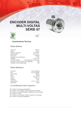
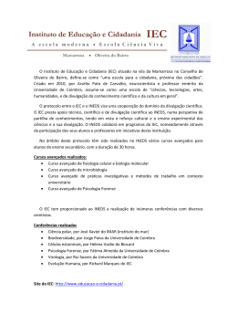
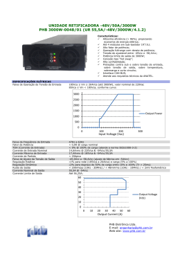
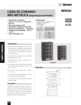
31100060
VOLTMETRO DIGITAL
TRIFÁSICO
I200 P GB 0506
DMK70
R
Lovato
DMK70
L1-L2
L2-L3
L3-L1
L1-N
L2-N
L3-N
A1
A2
L1
V
L3
L2
N
Esquema elétrico de ligação
Wiring diagram
N
L3
L2
L1
L1
L2
L3
N
600VAC
A2
A1
METER
DMK70
WARNING! This equipment is to be installed by trained
personnel, complying to current standard, to avoid
damages or safety hazards. Products illustrated herein
are subject to alteration and changes without prior notice.
● Technical data and descriptions in the documentation are accurate,
to the best of our knowledge, but no liabilities for errors, omissions
or contingencies arising therefrom are accepted.
● A load–break switch or circuit breaker must be included in the
electrical installation of the building. It must be installed close by the
equipment and within easy reach of the operator.
It must be marked the disconnecting device of the equipment:
IEC /EN 61010-1 § 6.12.2.1
● Fit the instrument in an enclosure or cabinet with minimum IP40
degree protection.
ATENÇÃO! Estes aparelhos devem ser instalados
por funcionário técnico qualificado, em conforme as
normas de instalações vigentes, para se evitar danos
a pessoas e instalações.
● Os produtos descritos neste documento são suceptiveis em
qualquer momento de evolução ou modificações. As descrições e
os dados no catalgo não podem portanto haver nenhum valor
contratual.
● Um interruptor ou disjuntor deve ser colocado na instalação
eletrica. Esse deve ser colocado próximo do aparelho e de facil
acesso da parte do operador.
Deve ser identificado como dispositivo di interrupção conforme as
normas IEC/ EN 61010-1 § 6.12.2.1
● Instalar o instrumento em caixa e/ou quadro elétrico com grau de
proteção minimo IP40
DESCRIÇÃO
• Medição da tensão em verdadeiro valor eficaz (TRMS).
• Memorização dos valores máximos e mínimos.
• Medição em Média Tensão através impostação relação do TP.
DESCRIPTION
• Voltage measures in True RMS
• Storing of minimum and maximum values
• Measure in medium voltage, by programming voltage transformers (VT).
VISUALIZAÇÃO DA MEDIÇÃO
• Apertar a tecla ”V” para visualizar a medida indicada na tabela.
Medida
L1-L2
Tensão de linha concatenada L1-L2
L2-L3
Tensão de linha concatenada L2-L3
L3-L1
Tensão de linha concatenada L3-L1
L1-N
Tensão de fase L1
L2-N
Tensão de fase L2
L3-N
Tensão de fase L3
Nota! Na falta da conexâo do neutro, as tensões de fase são referodas ao
centro estrela virtual do DMK. O ponto intermitente no display indica que a
medição é expressa em kVolt. A escrita “oL” no display indica sobrecarga
da entrada da medição.
VIEWING OF MEASURES
• Press the ”V” key to view the measures indicated in the table below:
Measure
L1-L2
Phase-to-phase voltage
L2-L3
Phase-to-phase voltage
L3-L1
Phase-to-phase voltage
L1-N
Phase voltage
L2-N
Phase voltage
L3-N
Phase voltage
Notes! In absence of the neutral connection, the phase voltages are
referred to the virtual DMK star point. The flashing dot on the display
indicates the measure is expressed in kilovolts. The “oL” indication means
a measure input overload.
VISUALIZAÇÃO DOS VALORES MÁXIMO E MÍNIMOS (“HI” e “LO”)
• Apertar a tecla “V” por 3s até visualizar “ - - - - “.
• Após 2s aparece a escrita “HI” seguida do valor máximo da medição
selezionada e sucessivamente a escrita “LO” seguida do valor mínimo.
• Apertar a tecla “V” para selecionar os valores ”HI” e “LO” das outras
medições.
• Se durante a visualização de “HI” e “LO”, se mantém apertado a tecla
“V” por 5s consecutivos, todos os valorees “HI” e “LO” serão anulados e
isto é , assumem os mesmo valores das medições presentes naquele
instante. A confirmação do anulamento no display aparecerá “CLr”
(cleared).
• Se não se aperta a tecla “V”, após haver mostrado por 3 vezes os
valores “HI” e “LO”, o instrumento recomeça a visualizzar normalmente
as medições.
Nota: os valores máximos permanecem memorizados mesmo na
ausência da tensão de alimentação.
PROGRAMAÇÃO DO TP PARA MEDIÇÃO EM MÉDIA TENSÃO
• Apertar a tecla ‘V’ por 3s até visualizar “- - - - “, então deixar a tecla e
apertar sucessivamente dentro 2s (antes de comparecer a escrita “HI”
e “LO”), até visualizar “P01”.
• Com “P01” no display apertar a tecla ”V” para acessar a programação
do TP, que é realizada em duas etapas:
Nota! A relação de transformação é composta de 5 cifras, 3 inteiras e 2
decimais. No display aparece primeiro as 3 cifras inteiras com un ponto
a direita, sucessivamente as 2 cifras decimais com o ponto a esquerda.
1° passo– Programação das cifras inteiras.
Apertar a tecla ‘V’ em correspondência da cifra intermitente para mudar
o valor da cifra. A posição da cifra intermitente muda após 2,5s da
ultima pressão da tecla.
Nota! Após a programação da cifra inteira aparece aquela decimal.
2° passo– Programação das cifras decimais.
Apertar a tecla ‘V’ em correspondência da cifra intermitente para mudar
o valor da cifra. A posição da cifra intermitente muda após 2,5s da
ultima pressão da tecla.
• Se após o final da programação o valor não reentra no campo previsto,
este será reconduzido entre os limites e será riproposto a programação
partindo do 1° passo.
• Se o valor é correto e não se aperta a tecla “V” por 2,5s, aparece P01.
• A visualização de P01, após 5s o instrumento memoriza o valor
saindo automaticamente da programação. Durante o tempo de
visualizaçãao de P01, é possível reentrare na programação apertando
a tecla “V”.
VIEWING OF MAXIMUM AND MINIMUM VALUES (“HI” and “LO”)
• Press the “V” key for at least 3 seconds until “ - - - - “ are shown.
• After 2 seconds, the wording “HI” is viewed followed by the maximum
value of the selected measure and then “LO” followed by the minimum
value.
• Press the “V” key to select the “HI” and “LO” values of the other measures.
• During the "HI" and "LO" viewing by keeping the “V” key maintained for
another 5 seconds, all “HI” and “LO” values are cleared, that is they
retain the same value of the measures present in that moment. To
confirm clearing, the wording “CLr” (cleared) is displayed.
• Instead, if the “V” key is no longer pushed, the instrument restores normal
measure viewing after “HI” and “LO” values have been shown for 3 times.
Note: the maximum values remain stored in memory even when the DMK
is not powered.
TABELA PARÂMETROS
Par
Função
P01
Relação do TP
Campo
1,00 ÷ 500,00
Code: DMK 70 MANUAL BR_MHPGB101A0705
Pag. 1/2
THREE-PHASE
DIGITAL VOLTMETER
Fabrica
1,00
VT SETTING FOR MEDIUM-VOLTAGE MEASURES
• Press the “V” key for 3 seconds until “- - - - “ are viewed, then release
the key and immediately press it again within 2 seconds (ie before "HI"
or "LO" is viewed) until “P01” is viewed.
• With “P01” displayed, press the ”V” key again to have access to the VT
setting that is done in two steps.
Note! The transformation ratio is composed by 5 digits, of which 3 are whole
numbers and 2 decimals. On the display, the 3 whole numbers are viewed
first, with a dot on the right, then the 2 decimals, with the dot on the left.
Step no.1 – Programming whole numbers
Press the ‘V’ key, when the digit flashes, to change its value. The
flashing digit changes position 2.5 seconds after any key has been
pressed.
Note ! The decimals are viewed after the whole numbers are set.
Step no. 2 – Programming decimals
• Press the ‘V’ key, when the digit flashes, to change its value. The
flashing digit changes position 2.5 seconds after any key has been
pressed.
• At the end of the programming, if the value is not within the setting
range, it will be reset to within the provided limits and restored to the
setting sequence, starting from step no.1 again.
• Instead, if the value is correct and the “V” key is not pressed for 2.5
seconds, P01 is viewed.
• At P01 viewing, the instrument stores the value after 5 seconds, and
automatically exits the setting. During P01 viewing time, setting can be
restored by pressing the “V” key.
TABLE OF PARAMETERS
PAR
Function
P01
VT ratio
12/05/2006
Range
1.00 – 500.00
Default
1.00
Características técnicas
Alimentação auxiliar
Tensão nominal Us
Dimensões mecanicas
Mechanical dimensions
Limite de funcionamento
Frequencia nominal
Potência consumida
Potência dissipada
Entradas voltimetricas
Tensâo nominal Ue
4.2mm
Campo de medição
104.7
mm
98.3
mm
90.0
mm
45.0
mm
53.5mm
5.0mm
43.7mm
58.0mm
24VCA
110…127VCA
220…240VCA
380…415VCA
0,85…1,1 Us
50…60Hz ±10%
3,2VA max
1,5W max
600VCA fase-fase
347VCAfase neutro
15…660VCA fase-fase
10…382VCA fase neutro
50…60Hz ±10%
True RMS
>1,1MΩ fase-fase
>0,55MΩ fase-neutro
Campo de frequencia
Tipo de medição
Impedância de entrada da
medição
Medição
Condições de medição
Temperatura +23°C ±1°C
Umidade relativa 45 ±15% R.H.
Precisão
±0,25% f.s. ±1 digito
Errores adicionais
Umididade relativa
±1 digito 60%…90% R.H.
Temperatura
±1 digito –20°…+60°C
Tensão de isolamento
Tensão nominal de tenuta
6kV
ao impulso Uimp
Tensão de tenuta a
4kV
frequencia de exercicio
Tensão nominal de
600VCA
isolamento Ui
Condições ambientais
Temperatura
-20...+60°C
funcionamento
Temperatura
-30...+80°C
armazenagem
Umidade relativa
<90%
Poluição ambiente máxima
Grau 3
Categoria de sobretensão
3
Conexões
Tipo de bornes
Fixos
Seção condutores
0.2…4.0 mm2
(min e max)
(24…12 AWG)
Torque de aperto
0,8Nm (7lbin)
Contenitor
Versão
3 modulos (DIN 43880)
Material
Poliammide RAL 7035
Montagem
Trilho 35mm (IEC/EN60715)
Ou parafuso usando clip extraível
Grau de proteção
IP40 no frontal
IP20 nos bornes
Peso
233g
Homologações e conformidades
Homologações
cULus ( em andamento )
Conformidade as normas
IEC/EN 61010-1, IEC/EN 61000-6-2,
CISPR 11/EN 55011, IEC/EN 61000-3-2,
IEC/EN 61000-3-3, IEC/EN 60068-2-61,
IEC/EN 60068-2-27, IEC/EN 60068-2-6,
UL508 C22.2-N°14-95
Code: DMK 70 MANUAL BR_MHPGB101A0705
Pag. 2/2
Technical characteristics
Auxiliary supply
Rated operational voltage
Us
Operating range
Rated frequency
Power consumption
Power dissipation
Voltage inputs
Rated voltage Ue
Measuring range
Frequency range
Measuring method
Measuring input
impedance
Measures
24VAC
110 … 127VAC
220 … 240VAC
380 … 415VAC
0.85 … 1.1 Us
50 … 60Hz ±10%
3.2VA max
1.5W max
600VAC phase-phase
347VAC phase-neutral
15 … 660VAC phase-phase
10 … 382VAC phase-neutral
50 … 60Hz ±10%
True RMS
>1.1MΩ phase-phase
>0.55MΩ phase-neutral
Measuring conditions
Temperature +23°C ±1°C
Relative Humidity 45 ±15% R.H.
Accuracy
±0.25% full scale ±1 digit
Additional errors
Relative humidity
±1 digit 60%...90% R.H.
Temperature
±1 digit –20°…+60°C
Insulation voltage
Rated impulse withstand
6kV
voltage Uimp
Power frequency withstand
4kV
voltage
Rated insulation
600VAC
voltage Ui
Ambient conditions
Operating temperature
-20…+60°C
Storage temperature
Relative humidity
Maximum pollution degree
Overvoltage category
Connections
Type of terminal
Conductor cross section
(min - max)
Tightening torque
Housing
Version
Material
Mounting/Fixing
Degree of protection
-30…+80°C
<90%
3
3
Fixed
0.2…4.0 mm2
(24…12 AWG)
0.8Nm (7lbin)
3 modules (DIN 43880)
Polyamide RAL 7035
35mm DIN rail (IEC/EN60715)
or by screws using extractible clips
IP40 on front
IP20 on terminals
233g
Weight
Certifications and compliance
Certifications
cULus pending
Comply with standards
IEC/EN 61010-1, IEC/EN 61000-6-2,
CISPR 11/EN 55011, IEC/EN 61000-3-2,
IEC/EN 61000-3-3, IEC/EN 60068-2-61,
IEC/EN 60068-2-27, IEC/EN 60068-2-6,
UL508 C22.2-N°14-95
12/05/2006
Baixar