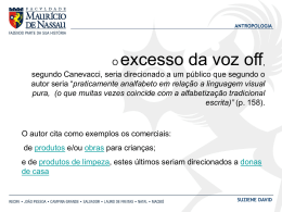
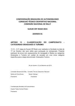
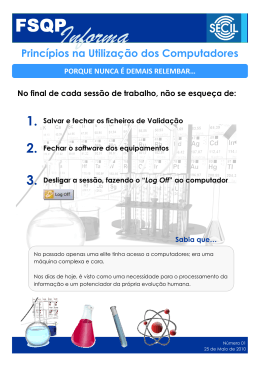
31100065
I205 I GB 0406
VOLTIMETRO, AMPERIMETRO E
WATTMETRO DIGITAL TRIFÁSICO
COM SAÍDA A RELÉ
THREE-PHASE DIGITAL VOLTMETER,
AMMETER AND WATTMETER
WITH RELAY OUTPUT
DMK75 R1
DMK75 R1
ATENÇÃO! Estes aparelhos devem ser
instalados por funcionário técnico qualificado, em
conforme as normas de instalações vigentes, para
se evitar danos a pessoas e instalações
I2
COM I1
R
I3
14
13
Lovato
DMK 75 R1
L1 L2 L3 V
TRIP
A1
3
A kW
2
A2
L1
1
N
L3
L2
Esquema elétrico de ligação
Wiring diagram
600VAC
COM
I3
I2
I1
L1
L2
L3
N
5AAC
13
14
A2
A1
METER
● Os produtos descritos neste documento são suceptiveis em
qualquer momento de evolução ou modificações. As descrições e
os dados no catalgo não podem portanto haver nenhum valor
contratual.
● Um interruptor ou disjuntor deve ser colocado na instalação
eletrica. Esse deve ser colocado próximo do aparelho e de facil
acesso pelo operador.
Deve ser identificado como dispositivo di interrupção conforme as
normas IEC/ EN 61010-1 § 6.12.2.1
● Instalar o instrumento em caixa e/ou quadro elétrico com grau de
proteção minimo IP40
WARNING! This equipment is to be installed by
qualified personnel, complying to current
standards, to avoid damages or safety hazards.
Products illustrated herein are subject to alteration
and changes without prior notice.
● Technical data and descriptions in the publication are accurate, to
the best of our knowledge, but no liabilities for errors, omissions or
contingencies arising therefrom are accepted.
● A load–break switch or circuit breaker must be included in the
electrical installation of the building. It must be installed close by the
equipment and within easy reach of the operator.
It must be marked as the disconnecting device of the equipment:
IEC /EN 61010-1 § 6.12.2.1
● Fit the instrument in an enclosure or cabinet with minimum IP40
degree protection.
DESCRIÇÃO
• Medição da tensão e da corrente em verdadeiro valor eficaz (TRMS).
• Memorização dos valores máximos e mínimos.
• Medição em Média Tensão através programação da relação do TP
• Funções de proteção: falta de fase, sequencia fase, tensão Max-Min,
corrente Max-Min, potência Max-Min, frequencia Max-Min,
desbalanceamento tensões e desbalancemento correntes.
• Relé de saída programável.
• Inserção através de TC externo.
DESCRIPTION
• Voltage and current measures in True RMS.
• Storing of minimum and maximum values.
• Measure in medium voltage, by programming voltage transformers (VT).
• Protection functions: phase loss, phase sequence, Max-Min voltage,
Max-Min current, Max-Min power, Max-Min frequency, voltage
asymmetry and current asymmetry.
• Programmable output relay.
• Connection through external TC.
VISUALIZAÇÃO DA MEDIÇÃO
• Apertar a tecla ”1” para visualizar a medida na sequencia como
indicada na tabela
• Apertar a tecla ”2” para visualizar as medições na ordem como
indicada na tabela ou a tecla ”3” para visualizar na ordem inversa.
VIEWING OF MEASURES
• Press key ”1” to view the measures indicated in the table below.
• Press key ”2” to view the measures in the order given by the table
indication or key “3” in the inverse order.
LED
Medição
L1 / L2 / V
Tensão de linha concatenata L1-L2
L2 / L3 / V
Tensão de linha concatenata L2-L3
L3 / L1 / V
Tensão de linha concatenata L3-L1
L1 / V
Tensão de fase L1
L2 / V
Tensão de fase L2
L3 / V
Tensão de fase L3
L1 / A
Corrente de fase L1
L2 / A
Corrente de fase L2
L3 / A
Corrente de fase L3
L1 / kW
Potência ativa de fase L1
L2 / kW
Potência ativa de fase L2
L3 / kW
Potência ativa de fase L3
L1 / L2 / L3 / kW Potência ativa total L1+L1+L3
Nota! Na falta da conexão do neutro, as tensões de fase são riferidas
ao centro estrela virtual do DMK. O ponto intermitente no display indica
que a medição é expressa em kAmpere, kVolts ou milhares de kWatts.
A escrita “oL” no display indica sobrecarga da entrada da medição.
LED
Measures
L1 / L2 / V
Phase-to-phase voltage of L1-L2
L2 / L3 / V
Phase-to-phase voltage of L2-L3
L3 / L1 / V
Phase-to-phase voltage of L3-L1
L1 / V
Phase voltage of L1
L2 / V
Phase voltage of L2
L3 / V
Phase voltage of L3
L1 / A
Phase current of L1
L2 / A
Phase current of L2
L3 / A
Phase current of L3
L1 / kW
Active power of phase L1
L2 / kW
Active power of phase L2
L3 / kW
Active power of phase L3
L1 / L2 / L3 / kW
Total active power of L1+L2+L3
Notes! In absence of the neutral connection, the phase voltages are
referred to the virtual DMK star point. The flashing dot on the display
indicates the measure is expressed in kilovolts, kiloamperes or thousand
of kW. The “oL” indication identifies a measure input overload.
VISUALIZAÇÃO DOS VALORES MÁXIMO E MÍNIMOS (“HI” e “LO”)
• Apertar a tecla “1” por 3s até visualizar “ - - - - “.
• Após 2s aparece a escrita “HI” seguida do valor máximo da medição
selezionada e sucessivamente a escrita “LO” seguida do valor
mínimo.
• Apertar a tecla “1”,”2” ou “3” para selecionar os valores ”HI” e “LO”
das outras medições.
.• Se durante a visualização de “HI” e “LO”, se mantém apertado a tecla
“1” por 5s consecutivos, todos os valorees “HI” e “LO” serão anulados
e isto é , assumem os mesmo valores das medições presentes
naquele instante. A confirmação do anulamento no display aparecerá
“CLr” (cleared)..
• Se não se aperta a tecla “1”, após haver mostrado por 3 vezes os
valores “HI” e “LO”, o instrumento recomeça a visualizzar
normalmente as medições.
Nota: os valores máximos permanecem memorizados mesmo na
ausência da tensão de alimentação.
VIEWING OF MAXIMUM AND MINIMUM VALUES (“HI” and “LO”)
• Press key “1” for at least 3 seconds until “ - - - - “ are shown.
• After 2 seconds, the wording “HI” is viewed followed by the maximum
value of the selected measure and then “LO” followed by the minimum
value.
• Press key “1”, “2” or “3” to select the “HI” and “LO” values of the other
measures.
• During the "HI" and "LO" viewing by keeping the “1” key maintained for
another 5 seconds, all “HI” and “LO” values are cleared, that is they
retain the same value of the measures present in that moment. To
confirm clearing, the wording “CLr” (cleared) is displayed.
• Instead, if key “1” is no longer pushed, the instrument restores normal
measure viewing after “HI” and “LO” values have been shown for 3 times.
Note: The maximum values remain memory stored even when the DMK
is not powered.
PROGRAMAÇÃO DOS PARÂMETROS
• Apertar contemporaneamente as teclas “2” e “3” por 5s até aparecer
“P0.01”.
• Apertar a tecla “2” ou “3” para selecionar o parâmetro da programar e
sucessivamente apertar a tecla “1” para acessar a modificação do
parâmetro.
• Apertar a tecla “2” ou “3” para modificar o parâmetro e
sucessivamente apertar a tecla “1” para acessar a escolha do novo
parâmetro da modificar.
Code: MHPGB201C0705
28/04/2005
SETTING OF PARAMETERS
• Press keys “2” and “3” together for 5 seconds until “P0.01“ is viewed.
• Press key “2” or “3” to select the parameter to program and then press
key “1” to access the parameter change.
• Press key “2” or “3” to change the parameter value and then press key
“1” to select a new parameter to change.
• During the parameter change, if neither key “2” or “3” is pressed for
more than 10 seconds, the instrument automatically returns to view
the parameter reference number.
Pag. 1/4
• Durante a modificação do parâmetro, se não se apertam as teclas “2”
e “3” por mais de 10s, o aparelho retorna automaticamente a
visualizar o numero do parâmetro.
• Durante a visualização do parâmetro, se si aperta
contemporaneamente as teclas “2” e “3” por 2s o aparelho sai da
programação memorizando os parâmetros. Ou então, sai
automaticamente sem memorização, se durante tal fase não si
aperta alguma tecla por um tempo de 120s.
• During the parameter viewing, if keys “2” and “3” are pressed
simultaneously for 2 seconds, the device will store the settings and
exit the programming mode. Otherwise, it automatically exits, without
parameter storing, should no key be pushed for more than 120
seconds during that phase.
TABELA PARÂMETROS
TABLE OF PARAMETERS
Par. Função
P0.01 Corrente primario TC
P0.02 Relação de transformação TP
-------------------
-----------------------------------------------------------------------------------------------------------------------------------------------
P1.01 Modo de controle relé (*)
P1.02 Temporização rearme automático
P1.03 Visualização alarmes (*)
-------------------
-----------------------------------------------------------------------------------------------------------------------------------------------
P2.01 Tipo de inserção voltimetrica (*)
P2.02 Tipo de inserção amperimetrica (*)
-------------------
-----------------------------------------------------------------------------------------------------------------------------------------------
P3.01
P3.02
P3.03
P3.04
P3.05
P3.06
P3.07
P3.08
P3.09
P3.10
P3.11
Tipo de controle tensão (*)
Tensão nominal (*)
Limite de tensão máxima
Temporização de máxima
Limite de tensão mínima
Temporização de mínima
Limite de falta de fase
Temporização falta de fase
Limite de desbalanceamento tensões
Temporização desbalanceamento
Sequencia das fases (*)
-------------------
-----------------------------------------------------------------------------------------------------------------------------------------------
P4.01 Corrente nominal
P4.02 Limite inibição proteçaos máxima (*)
P4.03 Temporização habilitação proteção
máxima
P4.04 Limite de corrente máxima
P4.05 Limite de corrente máxima a t=0 (*)
P4.06 Temporização de máxima
P4.07 Temporizaçao habilitação proteção
mínima (*)
P4.08 Limite de corrente mínima
P4.09 Temporização de mínima
P4.10 Hysteresis de Max ou Min (*)
P4.11 Limite de falta de corrente (*)
P4.12 Temporização de falta de fase
P4.13 Limite de desbalanceamento corrente
P4.14 Temporização desbalanceamento
-------------------
-----------------------------------------------------------------------------------------------------------------------------------------------
P5.01
P5.02
P5.03
P5.04
P5.05
Frequencia nominal
Limite de frequencia máxima
Temporização de máxima
Limite de frequencia mínima (*)
Temporização de mínima
-------------------
-----------------------------------------------------------------------------------------------------------------------------------------------
P6.01
P6.02
P6.03
P6.04
Tipo de controle potencia (*)
Potencia nominal kW
Limite de inibição proteção (*)
Temporização habilitação proteção
máxima
Limite de potencia máxima
Limite de potencia máxima a t=0 (*)
Temporização de máxima
Temporização habilitação proteção
mínima
Limite de potencia mínima
Temporização de mínima
Hysteresis de Max ou Min (*)
P6.05
P6.06
P6.07
P6.08
P6.09
P6.10
P6.11
Fabrica
Campo
5
1.00
5-10000
1.00-500.0
-------------------------------
-----------------------------------------------------------------
OFF
0.5
On
OFF / On / OFF.L
0.5-900.0s
OFF / On
-------------------------------
-----------------------------------------------------------------
3PHn
nor
3PHn-3PH-1PH
nor/bAL
-------------------------------
-----------------------------------------------------------------
-------------------
----------------------------------------------------------------------------------------------------------------------------------------------
LL
400
OFF
5.0
OFF
8.0
OFF
0.1
OFF
8.0
OFF
LL/Ln/LLn
15-50000
OFF / 102-120%
0.0-900.0s
OFF / 70-98%
0.0-900.0s
OFF / 5-85%
0.0-900.0s
OFF / 2.0-20.0%
0.5-900.0s
OFF / 1 / 2
P3.01
P3.02
P3.03
P3.04
P3.05
P3.06
P3.07
P3.08
P3.09
P3.10
P3.11
Voltage control type (*)
Rated voltage (*)
Maximum voltage threshold
Maximum delay
Minimum voltage threshold
Minimum delay
Phase loss threshold
Phase loss delay
Asymmetry threshold
Asymmetry delay
Phases sequence (*)
-------------------------------
-----------------------------------------------------------------
-------------------
----------------------------------------------------------------------------------------------------------------------------------------------
5
OFF
10.0
1-10000
OFF / 2-100%
0.0-900.0s
OFF
OFF
10.0
OFF
OFF / 102-200%
OFF / 110-600%
0.0-900.0s
OFF / 0.1-25.0s
P4.04
P4.05
P4.06
P4.07
Maximum current threshold
Maximum current threshold at t=0 (*)
Maximum delay
Minimum protections activation delay (*)
OFF
10.0
3
OFF
0.1
OFF
8.0
OFF / 5-98%
0.0-900.0s
3-50%
OFF / 2-100%
0.0-900.0s
OFF / 2.0-20.0%
0.5-900.0s
P4.08
P4.09
P4.10
P4.11
P4.12
P4.13
P4.12
Minimum current threshold
Minimum delay
Maximum or minimum hysteresis (*)
Current loss threshold (*)
Phase loss delay
Asymmetry threshold
Asymmetry delay
-------------------------------
-----------------------------------------------------------------
-------------------
----------------------------------------------------------------------------------------------------------------------------------------------
50Hz
OFF
5.0
OFF
5.0
50 / 60Hz
-------------------
----------------------------------------------------------------------------------------------------------------------------------------------
P1.01 Relay control mode (*)
P1.02 Automatic reset delay
P1.03 Alarms display (*)
-------------------
----------------------------------------------------------------------------------------------------------------------------------------------
P2.01 Voltage configuration type (*)
P2.02 Current configuration type (*)
P4.01 Rated current
P4.02 Max protections inhibition threshold (*)
P4.03 Maximum protection activation delay
P5.01
OFF / 101.0-110.0% P5.02
0.5-900.0s
P5.03
OFF / 90.0-99.0% P5.04
0.5-900.0s
P5.05
Rated frequency
Maximum frequency threshold
Maximum delay
Minimum frequency threshold (*)
Minimum delay
-------------------------------
-----------------------------------------------------------------
-------------------
----------------------------------------------------------------------------------------------------------------------------------------------
tot
100
OFF
10.0
tot/PHA
1-10000
OFF / 2-100%
0.0-900.0s
P6.01
P6.02
P6.03
P6.04
Power control type (*)
Rated power
Protections inhibition threshold (*)
Maximum protection activation delay
OFF
OFF
5.0
OFF
OFF / 101-200%
OFF / 110-600%
0.0-900.0s
OFF / 0.1-25.0
P6.05
P6.06
P6.07
P6.08
Maximum power threshold
Maximum power threshold at t=0 (*)
Maximum delay
Minimum protection activation delay (*)
OFF
8.0
3
OFF / 10-99%
0.0-900.0s
3-50%
(*) DESCRIÇÃO DOS PARÂMETROS
P1.01 – Com programação “OFF” o relé é normalmente desenergizado
e energiza após o intervento. Com programação “On” o relé é
normalmente energizado e se desenergiza após o intervento. Com
programação “OFF.L” o relé é normalmente desenergizado e se
energiza após o intervento memorizando o intervento. O rearme se
realiza apertando contemporaneamente por 0,5s as teclas no frontal “1”
e “3” ou interrompendo brevemente a alimentação do aprelho, mas a
condição que os valores controlados estejam nos limites programados.
P1.03 – Programar em “OFF” para disabilitar a visualização dos
alarmes existentes.
P2.01 – Para rede trifásica, na falta da conexão de neutro para NÃO
visualizar as tensões de fase programar “3PH”.
P2.02 – Para sistemas balanceados programar “bAL”. O sistema è
definido balanceado quando as 3 correntes e os relativos
desfasamentos são praticamentes iguais. Nesses casos é possível
Code: MHPGB201C0705
Par. Function
P0.01 CT primary current
P0.02 VT ratio
28/04/2005
P6.09 Minimum power threshold
P6.10 Minimum delay
P6.11 Maximum or minimum hysteresis (*)
(*) PARAMETERS DESCRIPTION
P1.01 – Programmed to “OFF”, the relay is normally de-energised and
energises after a tripping.
Programmed to "On", the relay is normally energised and de-energises
after a tripping.
Programmed to "OFF.L", the relay is normally de-energised and
energises after a tripping, which is stored by the relay Latch. Resetting
can take place once the controlled values return within programmed
limits, by either pressing keys “1” and "3" together on the unit front or
briefly removing power to the device.
P1.03 – Programmed to “OFF” to disable the viewing of existing alarm
conditions.
P2.01 – For three phase line, in absence of the neutral connection, to
NOT view the phase voltages, set to “3PH”.
P2.02 – For balanced systems, program to “bAL”. A system is defined
balanced when the 3 currents and the relative imbalances are practically
Pag. 2/4
conectar somente um TC aos bornes de entrada “COM” e “ I1”.
P3.01 – Escolha do controle da tensão concatenata “LL”, de fase “Ln”
ou ambas “LLn”. Na falta conexão de neutro programar “LL”.
P3.02 – Atenção!! A tensão nominal de referência da programar é
sempre aquela concatenata, mesmo se o controle for realizado com as
tensões de fase.
P3.11 – Controle sequencia das fases,1=direta, 2=inversa.
Atenção!! Lembramos de utilizar o controle de sequencia fase com
parâmetro P1.01=On.
P4.02 – A superação desse limite habilita a proteção de máxima
corrente (P4.04 e P4.05) após o tempo de atraso programado em
P4.03.
P4.05 – Tempo de intervento da potência máxima com tempo de atraso
t=0. Exemplo: com parâmetros programados P4.04=100%, P4.5=200%
e P4.06=10s, teremos que os tempos de intervento serão de 9s com
corrente a 110%, 5s com corrente a 150% e 0s com corrente a 200%.
P4.07 – A habilitação desse parâmetro inibe o intervento da corente
mínima (P4.08) e da falta de fase (P4.11), a partir da alimentação do
aparelho e pelo tempo programado. A mesma inibição se pode haver
apertando por 0,5s contemporaneamente as teclas “1” e “3” no frontal,
desde que a memoria de intervento (P1.02) seja programada em “On”.
P4.10 – Com ambos os limites de corrente Max e Min (P4.04 e P4.08)
habilitados este valor de Hysteresis é inoperante. Se si deseja habilitar a
hyisteresis para o limite de Max (P4.04) é necessário programar o limite
de Min (P4.08) em “OFF”, viceversa se si deseja habilitar a hysteresis
para o limite de Min (P4.08), o limite de Max (P4.04) deve ser
programdo em “OFF”.
P4.11 – Limite de intervento por falta de corrente em uma ou mais fase.
P5.04 – Atenção!! Na falta da tensão nos bornes de medição o
intervento da proteção de mínima frequencia é desabilitado.
P6.01 – Escolha do controle da potencia total ou de cada singola fase.
P6.03 – Ao superarento desse limite se habilita as proteções de
potência após a temporização programda em P6.04.
P6.06 – Limite de intervento dei potência máxima com tempo de
intervento t=0. Exemplo: com parâmetros programados P6.03=100%,
P6.4=200% e P6.05=10s, teremos que os tempos de intervento serão
de 9s com potência de 110%, 5s com potência de 150% e 0s com
potência de 200%.
P6.08 – A habiltação desse parâmetro desabilita o intervento de
potência mínima (P6.09), a partir da alimentação do aparelho pelo
tempo programado. A mesma inibição se pode obter apertando por 0,5s
contemporaneamente as teclas “1” e “3” no frontal, mas a condição que
a memoria de intervento (P1.02) seja programada em “On”.
P6.11 – Com ambos os limites de potência Max e Min (P6.05 e P6.09)
habilitados este valor de histeresys é inativo.Se si deseja ativar a
hyteresis para o limite de Max (P6.05) é necessário programare o limite
de Min (P6.09) em “OFF”, viceversa se si deseja habilitar a hysteresis
para o limite de Min (P6.09), o limite de Max (P6.05) deve ser
programado em “OFF”.
the same. In these cases, one only CT can be connected to input
terminals “COM” and “ I1”.
P3.01 – Choice of phase-to-phase voltage control “LL”, phase voltage
“Ln” or both “LLn”. In absence of the neutral connection, program “LL”.
P3.02 – Caution! The rated reference voltage to program is always the
phase-to-phase one although the control is done on the phase voltages.
P3.11 – Sequence control of the phases: 1=direct; 2=inverse.
Caution! It is recomended to use the phase sequence control with
parameter P1.01=On.
P4.02 – When this threshold is exceeded, maximum current protections
(P4.04 e P4.05) are enabled after the time delay programmed at P4.03.
P4.05 – Tripping threshold for maximum current with tripping time t=0.
Example: With parameter programming P4.02=100%, P4.3=200% and
P4.05=10sec, tripping times will be of 9s when current reaches 110%, 5s
when current reaches 150% and 0s when current reaches 200%.
P4.07 – Enabling this parameter momentarily inhibits minimum current
(P4.08) and phase loss (P4.11) tripping, starting from power up and
the set time. This same inihibition can be activated if this trip memory is
programmed to "On" at P1.02 and by pressing the front keys "1" and "3"
simultaneously for 0.5s.
P4.10 – With both Max and Min current thresholds (P4.04 and P4.08)
active, the hysteresis value is disable. If one needs the hysteresis with
Max threshold (P4.04), then the Min threshold (P4.08) must set to “OFF”.
Viceversa if one needs the hysteresis with Min threshold (P4.08), the
Max threshold (P4.04) must be set to “OFF”.
P4.11 – Tripping threshold for current loss on one or any phases.
P5.04 – Caution! In absence of power at measure terminals, the
protection tripping for minimum frequency is inhibited.
P6.01 – Choice of total power control or for each single phase.
P6.03 – When this threshold is exceeded, power protections are enabled
after the time delay programmed at P6.04.
P6.06 – Tripping threshold for maximum power with tripping delay t=0.
Exampled: With parameter programming P6.03=100%, P6.4=200% and
P6.05=10sec, tripping times will be 9s when power reaches 110%, 5s
with power at 150% and 0s with power at 200%.
P6.08 – Enabling this parameter momentarily inhibits minimum power
(P6.09) tripping, starting from power up and the set time. This same
inihibition can be activated if this trip memory is programmed to "On" at
P1.02 and by pressing the front keys "1" and "3" simultaneously for 0.5s.
P6.11 – With both Max and Min power thresholds (P6.05 and P6.09)
active, the hysteresis value is disabled. If one needs the hysteresis with
Max threshold (P6.05), then the Min threshold (P6.09) must be set to
“OFF”. Viceversa, if one needs the hysteresis with Min threshold (P6.09),
the Max threshold (P6.05) must be set to “OFF”.
INTERVENTO DA PROTEÇÃO E REARME
O aparelho vem fornecido com as proteções programadas em “OFF”,
isto é desabilitadas.Para habilitar as proteções é necessário programar
os limites de intervento os parâmetros conjugados a eles. Quando uma
medição sai dos limites programados aprece a visualização do alarme
relativo e alguns breves intermitência do Led “Trip” durante o tempo de
atraso do intervento. Ao terminar o tempo de atraso si tem o intervento
da proteção com o Led “Trip” aceso sem intermitência.No caso de
rearme automático (P1.01=“OFF” ou P1.01=“On”), se as medições estão
nos limites programados durante o tempo de atraso de rearme
automático o Led “Trip” si apaga brevemente, até apagar
completamente ao rearme da proteção.Os alarmes serão visualizados
todas as vezes que as medições sairem dos limites programados,
independentemente dos tempos de atraso ou rearme. Somente no caso
que vem memorizado o intervento (P1.01=”OFF.L”), também o alarme
que o provocou vem memorizado. A visualização dos alarmes
acontecem em sequencia e alternados com as medição.
PROTECTION TRIPPING AND RESETTING
The instrument is supplied with the protections all factory set to “OFF”,
that is disabled. To enable the protections, the tripping thresholds and
the relative parameters must be programmed. When a measure is out of
programmed limits, the relative alarm is viewed and the "Trip" LED
flashes, for short intervals, during the tripping time delay. At delay
lapsing, the protection trips and the "Trip" LED is constantly illuminated.
In the case of automatic resetting, i.e. P1.01="OFF" or P1.01="On",
should the measures return within limits, the "Trip" LED switches off
briefly during the automatic resetting delay and then remains switched off
at the protection resetting. The alarms are viewed each time the
measures are out of limits, regardless of the time or resetting delay. Only
when tripping is stored by the relay latch, i.e. P1.01="OFF.L", the alarm,
that caused it, will be stored as well.The viewing of the alarms sequence
is alternated with the measures.
Display
Tipo de proteção
U.Ph.L
Falta de fase (tensão)
Seq
Sequencia fase
U.HI
Tensão Max
U.LO
Tensão Min
U.Asy
Assimetria tensão
I.Ph.L
Falta de corrente
I.HI
Corrente Max
I.LO
Corrente Min
I.Asy
Assimetria corrente
F.HI
Frequencia Max
F.LO
Frequencia Min
P.HI
Potência Max
P.LO
Potência Min
N.B. A visualização dos alarmes pode ser desabilitada através do
correspondente parâmetro.
Display
Protection type
U.Ph.L
Phase loss voltage
Seq
Phase sequence
U.HI
Maximum voltage
U.LO
Minimum voltage
U.Asy
Voltage asymmetry
I.Ph.L
Current loss
I.HI
Maximum current
I.LO
Minimum current
I.Asy
Current asymmetry
F.HI
Maximum frequency
F.LO
Minimum frequency
P.HI
Maximum power
P.LO
Minimum power
Note! The alarm viewing can be disabled by the relative parameter.
Code: MHPGB201C0705
28/04/2005
Pag. 3/4
Caracteristicas técnicas
Alimentação auxiliar
Tensão nominal Us
Dimensões mecânicas
Mechanical dimensions
Limite de funcionamento
Frequencia nominal
Potência consumida
Potência dissipada
Entradas voltimetricas
Tensão nominal Ue
4.2mm
Campo de medição
104.7
mm
98.3
mm
90.0
mm
45.0
mm
53.5mm
Campo de frequencia
Tipo de medição
Impedância de entrada da
medição
Tempo de campionatura
Entrada amperimetricas
Corrente nominal Ie
Campo de medição
Campo de frequencia
Tipo de entrada
Technical characteristics
24VCA
110…127VCA
220…240VCA
380…415VCA
0,85…1,1 Us
50…60Hz ±10%
3,5VA max
1,8W max
600VAC fase-fase
347VAC fase neutro
35…660VAC fase-fase
20…382VAC fase neutro
50…60Hz ±10%
True RMS
>1,1MΩ fase-fase
>0,55MΩ fase-neutro
≈80ms
5A
0,05…6A
50…60Hz ±10%
Shunt
Através de TC externo
(baixa tensão) 5A max.
True RMS
+20% Ie
50A por 1 segundo
125A per 10ms
<0,6W por fase
≈80ms
Tipo de medição
Limite termico permanente
Limite termico de breve duração
Limite dinâmico
Autoconsumo
Tempo de campionatura
Medição
Condições de medição
Temperatura
+23°C ±1°C
Umidade relativa
45 ±15% R.H.
Precisão tensão
±0,25% f.s. ±1 digito
Precisão corrente
±0,5% f.s. ±1 digito
Precisão potência
±1% f.s. ±1 digito
(com cosϕ = 0,70…1,00)
Erros adicionais
Umidade relativa
±1 digito 60%…90% R.H.
Temperatura
±1 digito –20…+60°C
Relé de saída
Saída
1 NO
Tensião nominal
250VCA
AC1 8A 250VCA / B300
Caracteristica conforme
Auxiliary supply
Rated operational voltage Us
Operating range
Rated frequency
Power consumption
Power dissipation
Voltage inputs
Rated voltage Ue
Measuring range
Frequency range
Measuring method
Measuring input impedance
Acquisition time
Current inputs
Rated current Ie
Measuring range
Frequency range
Type of input
Measuring method
Overload capacity
Overload peak
Dynamic limit
Self-consumption
Acquisition time
Measures
24VAC
110 … 127VAC
220 … 240VAC
380 … 415VAC
0.85 … 1.1 Us
50 … 60Hz ±10%
3.5VA max
1.8W max
600VAC phase-phase
347VAC phase-neutral
35 … 660VAC phase-phase
20 … 382VAC phase-neutral
50 … 60Hz ±10%
True RMS
>1.1MΩ phase-phase
>0.55MΩ phase-neutral
≈80ms
5A
0.05…6A
50 … 60Hz ±10%
Shunt
Connected by an external CT
(low voltage) max 5A
True RMS
+20% Ie
50A for 1 second
125A for 10ms
<0.6W per phase
≈80ms
Measuring conditions
Temperature +23°C ±1°C
Relative Humidity 45 ±15% R.H.
Voltage accuracy
±0.25% full scale ±1 digit
Current accuracy
±0.5% full scale ±1 digit
Power accuracy
±1% full scale ±1 digit
(with cosϕ = 0.70…1.00)
Additional errors
Relative humidity
±1 digit 60%...90% R.H.
Temperature
±1 digit –20…+60°C
Relay output
Number of outputs
1 NO
Rated voltage
250VAC
Designation per IEC/EN 60947-5-1
AC1 8A 250VAC / B300
IEC/EN 60947-5-1
5.0mm
43.7mm
58.0mm
Vida elétrica (operações)
Vida mecânica (operações)
Tensão de isolamento
Tensão nominal de resistência ao
impulso Uimp
Tensão de resitência a frequencia
de funcionamento
Tensão nominal de isolamento Ui
Condições ambientais
Temperatura de funcionamento
Temperatura de armazenagem
Umidade relativa
Poluição ambiente máxima
Categoria de sobretensão
Conexões
Tipo de bornes
Seção condutores
(min e max)
Torque de aperto
Contenitor
Esecução
Material
Montagem
Grau de proteção
105
30x106
6kV
4kV
600VCA
-20...+60°C
-30...+80°C
<90%
Grau 3
3
Fixos
0.2…4.0 mm2
(24…12 AWG)
0,8Nm (7lbin)
3 modulos (DIN 43880)
Poliamide RAL 7035
Trilho 35mm (IEC/EN60715)
Ou parafuso através de clip
estraível
IP40 no frontal
IP20 nos bornes
280g
Peso
Homologações e conformidades
Homologações
cULus ( em andamento)
Conformidades as normas
IEC/EN 61010-1, IEC/EN 61000-6-2, CISPR 11/EN 55011,
IEC/EN 61000-3-2, IEC/EN 61000-3-3, IEC/EN 60068-2-61,
IEC/EN 60068-2-27, IEC/EN 60068-2-6, UL508 C22.2-N°14-95
Code: MHPGB201C0705
28/04/2005
Electrical life (operations)
Mechanical life (operations)
Insulation voltage
Rated impulse withstand voltage
Uimp
Power frequency withstand
voltage
Rated insulation
voltage Ui
Ambient conditions
Operating temperature
Storage temperature
Relative humidity
Maximum pollution degree
Overvoltage category
Connections
Type of terminal
Conductor cross section (min max)
Tightening torque
Housing
Version
Material
Mounting/Fixing
Degree of protection
105
30x106
6kV
4kV
600VAC
-20…+60°C
-30…+80°C
<90%
3
3
Fixed
0.2…4.0 mm2
(24…12 AWG)
0.8Nm (7lbin)
3 modules (DIN 43880)
Polyamide RAL 7035
35mm DIN rail (IEC/EN60715)
or by screws using extractible
clips
IP40 on front
IP20 on terminals
280g
Weight
Certifications and compliance
Certifications
cULus pending
Comply with standards
IEC/EN 61010-1, IEC/EN 61000-6-2, CISPR 11/EN 55011, IEC/EN
61000-3-2, IEC/EN 61000-3-3, IEC/EN 60068-2-61, IEC/EN 60068-227, IEC/EN 60068-2-6, UL508 C22.2-N°14-95
Pag. 4/4
Baixar